B Reference Procedures
Inventory File Preparation
Introduction
OCCNE Installation automation uses information within an OCCNE Inventory file to provision servers and virtual machines, install cloud native components, as well as configure all of the components within the cluster such that they constitute a cluster conformant to the OCCNE platform specifications. To assist with the creation of the OCCNE Inventory, a boilerplate OCCNE Inventory is provided. The boilerplate inventory file requires the input of site-specific information.
This document outlines the procedure for taking the OCCNE Inventory boilerplate and creating a site specific OCCNE Inventory file usable by the OCCNE Install Procedures.
Inventory File Overview
The inventory file is an Initialization (INI) formatted file. The basic elements of an inventory file are hosts, properties, and groups.
- A host is defined as a Fully Qualified Domain Name (FQDN). Properties are defined as key=value pairs.
- A property applies to a specific host when it appears on the same line as the host.
- Square brackets define group names. For example host_hp_gen_10 defines the group of physical HP Gen10 machines. There is no explicit "end of group" delimiter, rather group definitions end at the next group declaration or the end of the file. Groups can not be nested.
- A property applies to an entire group when it is defined under a group heading not on the same line as a host.
- Groups of groups are formed using the children keyword. For example, the occne:childrencreates an occne group comprised of several other groups.
- Inline comments are not allowed.
Table B-1 Base Groups
| Group Name | Description/Comments |
|---|---|
| host_hp_gen_10 | The list of all physical hosts in the
OCCNE cluster. Each host in this group must also have several
properties defined (outlined below).
The default configuration of a node in this group is for a Gen 10 RMS with modules providing boot interfaces at Linux interface identifiers 'eno5' and 'eno6'. For Gen 10 bladesthe boot interfaces are usually 'eno1' and 'eno2' and should be specified by adding the following properties (outlined below).
|
| host_kernel_virtual | The list of all virtual hosts in the OCCNE cluster.
Each host in this group must have the same properties defined as
above with the exception of the ilo
|
| kvm_hosts:children | The list of all physical hosts which will be hosting the virtual hosts. This should be the set data_store and kube-master. Do not modify. |
| occne:children | Do not modify the children of the occne |
| occne:vars | This is a list of variables representing configurable site-specific data. While some variables are optional, the ones listed in the boilerplate should be defined with valid values. If a given site does not have applicable data to fill in for a variable, the OCCNE installation or engineering team should be consulted. Individual variable values are explained in subsequent sections. |
| data_store | The list of Storage Hosts |
| kube-master | The list of Master Node hosts where kubernetes master components run. |
| etcd | The list of hosts that compose the etcd server. Should always be an odd number. This set is the same list of nodes as the kube-master |
| kube-node | The list of Worker Nodes. Worker Nodes are where kubernetes pods run and should be comprised of the bladed hosts. |
| k8s-cluster:children | Do not modify the children of k8s-cluster |
| bastion_hosts | The list of Bastion Hosts name.fqdn (ex: bastion-1.icemark.lab.us.oracle.com) |
Data Tier Groups
The MySQL service is comprised of several nodes running on virtual machines on RMS hosts. This collection of hosts is referred to as the MySQL Cluster. Each host in the MySQL Cluster requires a NodeID parameter. Each host in the MySQL cluster is required to have a NodeID value that is unique per site across the MySQL cluster. Additional parameter range limitations are outlined below.
Table B-2 Data Tier Groups
| Group Name | Description/Comments |
|---|---|
| mysqlndb_mgm_nodes | The list of MySQL Management nodes. In OCCNE, this
group consists of three virtual machines distributed equally among
the kube-masternodes. These nodes must have a NodeId parameter
defined:
|
| mysqlndb_data_nodes_ng0 | The list of MySQL Data nodes, In OCCNE, this group
consists of two virtual machine distributed equally among the
Storage Hosts. Each VM in this group should belong to the different
Storage Hosts. Requires a NodeId parameter.
|
| mysqlndb_data_nodes_ng1 | The list of MySQL Data nodes, In OCCNE, this group
consists of two virtual machine distributed equally among the
Storage Hosts. Each VM in this group should belong to the different
Storage Hosts. Requires a NodeId parameter.
|
| mysqlndb_data_nodes | The list of MySQL Data node groups. In OCCNE, this group consists of 2 groups, each groups consists of two virtual machines distributed equally among the Storage Hosts. |
| mysqlndb_sql_nodes | List of MySQL nodes. In OCCNE 1.0 this group
consists of two virtual machines distributed equally among the
Storage Hosts. Requires a NodeId parameters.
|
| mysqlndb_all_nodes:children | Do not modify the children of the mysqlndb_all_nodes group. |
| mysqlndb_all_nodes:vars | This is a list of variables representing configurable site-specific data. While some variables are optional, the ones listed in the boilerplate should be defined with valid values. If a given site does not have applicable data to fill in for a variable, the OCCNE installation or engineering team should be consulted. Individual variable values are explained in subsequent sections. |
Prerequisites
- Prior to initiating the procedure steps, the Inventory Boilerplate should be copied to a system where it can be edited and saved for future use. Eventually the hosts.ini file needs to be transferred to OCCNE servers.
Procedure
OCCNE Cluster Name
In order to provide each OCCNE host with a unique FQDN, the first step in composing the OCCNE Inventory is to create an OCCNE Cluster domain suffix. The OCCNE Cluster domain suffix starts with a Top-level Domain (TLD). The structure of a TLD is maintained by various government and commercial authorities. Additional domain name levels help identify the cluster and are added to help convey additional meaning. OCCNE suggests adding at least one "ad hoc" identifier and at least one "geographic" and "organizational" identifier.
Geographic and organizational identifiers may be multiple levels deep.
An example OCCNE Cluster Name using the following identifiers is below:
- Ad hoc Identifier: atlantic
- Organizational Identifier: lab1
- Organizational Identifier: research
- Geographical Identifier (State of North Carolina): nc
- Geographical Identifier (Country of United States): us
- TLD: oracle.com
Example OCCNE Cluster name: atlantic.lab1.research.nc.us.oracle.com
Create host_hp_gen_10 and host_kernel_virtual group lists
Using the OCCNE Cluster domain suffix created above, fill out the inventory boilerplate with the list of hosts in the host_hp_gen_10 and host_kernel_virtual groups. The recommended host name prefix for nodes in the host_hp_gen_10 groups is "k8s-x" where x is a number 1 to N. Kubernetes "master" and "worker" nodes should not be differentiated using the host name. The recommended host name prefix for nodes in the host_kernel_virtual group is "db-x" where x is a number 1 to N. MySQL Cluster nodes should not be differentiated using host names.
Edit occne:vars
Edit the values in the occne:vars group to reflect site specific data. Values in the occne:vars group are defined below:
Table B-3 Edit occne:vars
| Var Name | Description/Comment |
|---|---|
| occne_cluster_name | Set to the OCCNE Cluster Name generated in step 2.1 above. |
| subnet_ipv4 | Set to the subnet of the network used to assign IPs for OCCNE hosts |
| subnet_cidr | Appears this is not used so does not need to be included. If it does need to be included, set to the cidr notation for the subnet. For example /24 |
| netmask | Set appropriately for the network used to assign IPs for OCCNE hosts. |
| broadcast_address | Set appropriately for the network used to assign IPs for OCCNE hosts. |
| default_route | Set to the IP of the TOR switch. |
| name_server | 'none' |
| ntp_server | Set to the IP of the TOR switch. |
| occne_repo_host | Set to the hostname of the bootstrap host initially. This defaults to "bootstrap". It can remain as that value or the user can change it to their own specifications but they must adhere to hostname conventions. |
| occne_repo_host_address | Set to the internal (ansible_host) IPv4 address of the occne_repo_host. |
| pxe_install_lights_out_usr | Set to the user name configured for iLO admins on each host in the OCCNE Frame. |
| pxe_install_lights_out_passwd | Set to the password configured for iLO admins on each host in the OCCNE Frame. |
| ilo_vlan_id | Set to the VLAN ID of the ILO network For Ex: 2 |
| ilo_subnet_ipv4 | Set to the subnet of the ILO network used to assign IPs for Storage hosts |
| ilo_subnet_cidr | Set to the cidr notation for the subnet. For example 24 |
| ilo_netmask | Set appropriately for the network used to assign ILO IPs for Storage hosts. |
| ilo_broadcast_address | Set appropriately for the network used to assign ILO IPs for OCCNE hosts. |
| ilo_default_route | Set to the ILO VIP of the TOR switch. |
| mgmt_vlan_id | Set to the VLAN ID of the Management network For Ex: 4 |
| mgmt_subnet_ipv4 | Set to the subnet of the Management network used to assign IPs for Storage hosts |
| mgmt_subnet_cidr | Set to the cidr notation for the Management subnet. For example 29 |
| mgmt_netmask | Set appropriately for the network used to assign Management IPs for Storage hosts. |
| mgmt_broadcast_address | Set appropriately for the network used to assign Management IPs for Storage hosts. |
| mgmt_default_route | Set to the Management VIP of the TOR switch. |
| signal_vlan_id | Set to the VLAN ID of the Signalling network For Ex: 5 |
| signal_subnet_ipv4 | Set to the subnet of the Signalling network used to assign IPs for Storage hosts |
| signal_subnet_cidr | Set to the cidr notation for the Signalling subnet. For example 29 |
| signal_netmask | Set appropriately for the network used to assign Signalling IPs for Storage hosts and MySQL SQL Node VM's. |
| signal_broadcast_address | Set appropriately for the network used to assign Signalling IPs for Storage hosts and MySQL SQL Node VM's. |
| signal_default_route | Set to the Signalling VIP of the TOR switch. |
| occne_snmp_notifier_destination | Set to the address of SNMP trap receiver. For Ex: "127.0.0.1:162" |
Edit mysqlndb_all_nodes:vars
Table B-4 Edit mysqlndb_all_nodes:vars
| Num | Var Name | Description/Comment |
|---|---|---|
| 1 | occne_mysqlndb_NoOfReplicas | Number of Replicas with in the MySQL NDB Cluster. For Ex: 2 |
| 2 | occne_mysqlndb_DataMemory | Size of Data Memory(RAM) assigned to each MySQL Data Nodes. For Ex: 12G |
OCCNE Inventory Boilerplate
The hosts_sample.ini file is obtained via MOS. It is delivered in the occne-config-<release_number>.tgz file.
Installation Preflight Checklist
Introduction
This procedure identifies the pre-conditions necessary to begin installation of a CNE frame. This procedure is to be referenced by field install personnel to ensure the frame is properly assembled and the inventory of needed artifacts are present before installation activities are attempted.
The primary function of this procedure is to identify the prerequisites necessary for installation to begin.
Confirm hardware components are installed in the frame and connected as per the tables below
Figure B-1 Rackmount ordering

OCCNE frame installation is expected to be complete prior to executing any software installation. This section provides reference to prove the frame installation is completed as expected by software installation tools.
Enclosure Switch Connections
Table B-5 Enclosure Switch Connections
| Switch Port Name/ID (From) | Destination (To) | Cable Type | Module Required |
|---|---|---|---|
| Internal 1 | Blade 1, NIC (1 for IObay1, 2 for IObay2) | Internal | None |
| Internal 2 | Blade 2, NIC (1 for IObay1, 2 for IObay2) | Internal | None |
| Internal 3 | Blade 3, NIC (1 for IObay1, 2 for IObay2) | Internal | None |
| Internal 4 | Blade 4, NIC (1 for IObay1, 2 for IObay2) | Internal | None |
| Internal 5 | Blade 5, NIC (1 for IObay1, 2 for IObay2) | Internal | None |
| Internal 6 | Blade 6, NIC (1 for IObay1, 2 for IObay2) | Internal | None |
| Internal 7 | Blade 7, NIC (1 for IObay1, 2 for IObay2) | Internal | None |
| Internal 8 | Blade 8, NIC (1 for IObay1, 2 for IObay2) | Internal | None |
| Internal 9 | Blade 9, NIC (1 for IObay1, 2 for IObay2) | Internal | None |
| Internal 10 | Blade 10, NIC (1 for IObay1, 2 for IObay2) | Internal | None |
| Internal 11 | Blade 11, NIC (1 for IObay1, 2 for IObay2) | Internal | None |
| Internal 12 | Blade 12, NIC (1 for IObay1, 2 for IObay2) | Internal | None |
| Internal 13 | Blade 13, NIC (1 for IObay1, 2 for IObay2) | Internal | None |
| Internal 14 | Blade 14, NIC (1 for IObay1, 2 for IObay2) | Internal | None |
| Internal 15 | Blade 15, NIC (1 for IObay1, 2 for IObay2) | Internal | None |
| Internal 16 | Blade 16, NIC (1 for IObay1, 2 for IObay2) | Internal | None |
| External 1 | Uplink 1 to ToR Switch (A for IObay1, B for IObay2) | Fiber (multi-mode) | 10GE Fiber |
| External 2 | Uplink 2 to ToR Switch (A for IObay1, B for IObay2) | Fiber (multi-mode) | 10GE Fiber |
| External 3 | Uplink 3 to ToR Switch (A for IObay1, B for IObay2) | Fiber (multi-mode) | 10GE Fiber |
| External 4 | Uplink 4 to ToR Switch (A for IObay1, B for IObay2) | Fiber (multi-mode) | 10GE Fiber |
| External 5 | Not Used | None | None |
| External 6 | Not Used | None | None |
| External 7 | Not Used | None | None |
| External 8 | Not Used | None | None |
| Internal 17 | Crosslink to IObay (2 for IObay1, 1 for IObay2) | Internal | None |
| Internal 18 | Crosslink to IObay (2 for IObay1, 1 for IObay2) | Internal | None |
| Management | OA | Internal | None |
ToR Switch Connections
This section contains the point to point connections for the switches. The switches in the solution will follow the naming scheme of "Switch<series number>", i.e. Switch1, Switch2, etc; where Switch1 is the first switch in the solution, and switch2 is the second. These two form a redundant pair. The switch datasheet is linked here: https://www.cisco.com/c/en/us/products/collateral/switches/nexus-9000-series-switches/datasheet-c78-736651.html.
Table B-6 ToR Switch Connections
| Switch Port Name/ID (From) | From Switch 1 to Destination | From Switch 2 to Destination | Cable Type | Module Required |
|---|---|---|---|---|
| 1 | RMS 1, FLOM NIC 1 | RMS 1, FLOM NIC 2 | Cisco 10GE DAC | Integrated in DAC |
| 2 | RMS 1, iLO | RMS 2, iLO | CAT 5e or 6A | 1GE Cu SFP |
| 3 | RMS 2, FLOM NIC 1 | RMS 2, FLOM NIC 2 | Cisco 10GE DAC | Integrated in DAC |
| 4 | RMS 3, FLOM NIC 1 | RMS 3, FLOM NIC 2 | Cisco 10GE DAC | Integrated in DAC |
| 5 | RMS 3, iLO | RMS 4, iLO | CAT 5e or 6A | 1GE Cu SFP |
| 6 | RMS 4, FLOM NIC 1 | RMS 4, FLOM NIC 2 | Cisco 10GE DAC | Integrated in DAC |
| 7 | RMS 5, FLOM NIC 1 | RMS 5, FLOM NIC 2 | Cisco 10GE DAC | Integrated in DAC |
| 8 | RMS 5, iLO | RMS 6, iLO | CAT 5e or 6A | 1GE Cu SFP |
| 9 | RMS 6, FLOM NIC 1 | RMS 6, FLOM NIC 2 | Cisco 10GE DAC | Integrated in DAC |
| 10 | RMS 7, FLOM NIC 1 | RMS 7, FLOM NIC 2 | Cisco 10GE DAC | Integrated in DAC |
| 11 | RMS 7, iLO | RMS 8, iLO | CAT 5e or 6A | 1GE Cu SFP |
| 12 | RMS 8, FLOM NIC 1 | RMS 8, FLOM NIC 2 | Cisco 10GE DAC | Integrated in DAC |
| 13 | RMS 9, FLOM NIC 1 | RMS 9, FLOM NIC 2 | Cisco 10GE DAC | Integrated in DAC |
| 14 | RMS 9, iLO | RMS 10, iLO | CAT 5e or 6A | 1GE Cu SFP |
| 15 | RMS 10, FLOM NIC 1 | RMS 10, FLOM NIC 2 | Cisco 10GE DAC | Integrated in DAC |
| 16 | RMS 11, FLOM NIC 1 | RMS 11, FLOM NIC 2 | Cisco 10GE DAC | Integrated in DAC |
| 17 | RMS 11, iLO | RMS 12, iLO | CAT 5e or 6A | 1GE Cu SFP |
| 18 | RMS 12, FLOM NIC 1 | RMS 12, FLOM NIC 2 | Cisco 10GE DAC | Integrated in DAC |
| 19 | Enclosure 6, OA 1, Mngt | Enclosure 6, OA 2, Mngt | CAT 5e or 6A | 1GE Cu SFP |
| 20 | Enclosure 6, IOBay 1, Port 17 | Enclosure 6, IOBay 2, Port 17 | Cisco 10GE DAC | Integrated in DAC |
| 21 | Enclosure 6, IOBay 1, Port 18 | Enclosure 6, IOBay 2, Port 18 | Cisco 10GE DAC | Integrated in DAC |
| 22 | Enclosure 6, IOBay 1, Port 19 | Enclosure 6, IOBay 2, Port 19 | Cisco 10GE DAC | Integrated in DAC |
| 23 | Enclosure 6, IOBay 1, Port 20 | Enclosure 6, IOBay 2, Port 20 | Cisco 10GE DAC | Integrated in DAC |
| 24 | Enclosure 5, OA 1, Mngt | Enclosure 5, OA 2, Mngt | CAT 5e or 6A | 1GE Cu SFP |
| 25 | Enclosure 5, IOBay 1, Port 17 | Enclosure 5, IOBay 2, Port 17 | Cisco 10GE DAC | Integrated in DAC |
| 26 | Enclosure 5, IOBay 1, Port 18 | Enclosure 5, IOBay 2, Port 18 | Cisco 10GE DAC | Integrated in DAC |
| 27 | Enclosure 5, IOBay 1, Port 19 | Enclosure 5, IOBay 2, Port 19 | Cisco 10GE DAC | Integrated in DAC |
| 28 | Enclosure 5, IOBay 1, Port 20 | Enclosure 5, IOBay 2, Port 20 | Cisco 10GE DAC | Integrated in DAC |
| 29 | Enclosure 4, OA 1, Mngt | Enclosure 4, OA 2, Mngt | CAT 5e or 6A | 1GE Cu SFP |
| 30 | Enclosure 4, IOBay 1, Port 17 | Enclosure 4, IOBay 2, Port 17 | Cisco 10GE DAC | Integrated in DAC |
| 31 | Enclosure 4, IOBay 1, Port 18 | Enclosure 4, IOBay 2, Port 18 | Cisco 10GE DAC | Integrated in DAC |
| 32 | Enclosure 4, IOBay 1, Port 19 | Enclosure 4, IOBay 2, Port 19 | Cisco 10GE DAC | Integrated in DAC |
| 33 | Enclosure 4, IOBay 1, Port 20 | Enclosure 4, IOBay 2, Port 20 | Cisco 10GE DAC | Integrated in DAC |
| 34 | Enclosure 3, OA 1, Mngt | Enclosure 3, OA 2, Mngt | CAT 5e or 6A | 1GE Cu SFP |
| 35 | Enclosure 3, IOBay 1, Port 17 | Enclosure 3, IOBay 2, Port 17 | Cisco 10GE DAC | Integrated in DAC |
| 36 | Enclosure 3, IOBay 1, Port 18 | Enclosure 3, IOBay 2, Port 18 | Cisco 10GE DAC | Integrated in DAC |
| 37 | Enclosure 3, IOBay 1, Port 19 | Enclosure 3, IOBay 2, Port 19 | Cisco 10GE DAC | Integrated in DAC |
| 38 | Enclosure 3, IOBay 1, Port 20 | Enclosure 3, IOBay 2, Port 20 | Cisco 10GE DAC | Integrated in DAC |
| 39 | Enclosure 2, OA 1, Mngt | Enclosure 2, OA 2, Mngt | CAT 5e or 6A | 1GE Cu SFP |
| 40 | Enclosure 2, IOBay 1, Port 17 | Enclosure 2, IOBay 2, Port 17 | Cisco 10GE DAC | Integrated in DAC |
| 41 | Enclosure 2, IOBay 1, Port 18 | Enclosure 2, IOBay 2, Port 18 | Cisco 10GE DAC | Integrated in DAC |
| 42 | Enclosure 2, IOBay 1, Port 19 | Enclosure 2, IOBay 2, Port 19 | Cisco 10GE DAC | Integrated in DAC |
| 43 | Enclosure 2, IOBay 1, Port 20 | Enclosure 2, IOBay 2, Port 20 | Cisco 10GE DAC | Integrated in DAC |
| 44 | Enclosure 1, OA 1, Mngt | Enclosure 1, OA 2, Mngt | CAT 5e or 6A | 1GE Cu SFP |
| 45 | Enclosure 1, IOBay 1, Port 17 | Enclosure 1, IOBay 2, Port 17 | Cisco 10GE DAC | Integrated in DAC |
| 46 | Enclosure 1, IOBay 1, Port 18 | Enclosure 1, IOBay 2, Port 18 | Cisco 10GE DAC | Integrated in DAC |
| 47 | Enclosure 1, IOBay 1, Port 19 | Enclosure 1, IOBay 2, Port 19 | Cisco 10GE DAC | Integrated in DAC |
| 48 | Enclosure 1, IOBay 1, Port 20 | Enclosure 1, IOBay 2, Port 20 | Cisco 10GE DAC | Integrated in DAC |
| 49 | Mate Switch, Port 49 | Mate Switch, Port 49 | Cisco 40GE DAC | Integrated in DAC |
| 50 | Mate Switch, Port 50 | Mate Switch, Port 50 | Cisco 40GE DAC | Integrated in DAC |
| 51 | OAM Uplink to Customer | OAM Uplink to Customer | 40GE (MM or SM) Fiber | 40GE QSFP |
| 52 | Signaling Uplink to Customer | Signaling Uplink to Customer | 40GE (MM or SM) Fiber | 40GE QSFP |
| 53 | Unused | Unused | ||
| 54 | Unused | Unused | ||
| Management (Ethernet) | RMS 1, NIC 2 (1GE) | RMS 1, NIC 3 (1GE) | CAT5e or CAT 6A | None (RJ45 port) |
| Management (Serial) | Unused | Unused | None | None |
Rackmount Server Connections
Server quickspecs can be found here: https://h20195.www2.hpe.com/v2/getdocument.aspx?docname=a00008180enw
The HP DL380 Gen10 RMS will be configured with an iLO, a 4x1GE LOM, and a 2x10GE SFP+ FLOM.
- iLO. The integrated Lights Out management interface (iLO) contains an ethernet out of band management interface for the server. This connection is 1GE RJ45.
- 4x1GE LOM. For most servers in the solution, their 4x1GE LOM ports will be unused. The exception is the first server in the first frame. This server will serve as the management server for the ToR switches. In this case, the server will use 2 of the LOM ports to connect to ToR switches' respective out of band ethernet management ports. These connections will be 1GE RJ45 (CAT 5e or CAT 6).
- 2x10GE FLOM. Every server will be equipped with a 2x10GE Flex LOM card (or FLOM). These will be for in-band, or application and solution management traffic. These connections are 10GE fiber (or DAC) and will terminate to the ToR switches' respective SFP+ ports.
All RMS in the frame will only use the 10GE FLOM connections, except for the "management server", the first server in the frame, which will have some special connections as listed below.
Table B-7 Rackmount Server Connections
| Server Interface | Destination | Cable Type | Module Required | Notes |
|---|---|---|---|---|
| Base NIC1 (1GE) | Unused | None | None | |
| Base NIC2 (1GE) | Switch1A Ethernet Mngt | CAT5e or 6a | None | Switch Initialization |
| Base NIC3 (1GE) | Switch1B Ethernet Mngt | CAT5e or 6a | None | Switch Initialization |
| Base NIC4 (1GE) | Unused | None | None | |
| FLOM NIC1 | Switch1A Port 1 | Cisco 10GE DAC | Integrated in DAC | OAM, Signaling, Cluster |
| FLOM NIC2 | Switch1B Port 1 | Cisco 10GE DAC | Integrated in DAC | OAM, Signaling, Cluster |
| USB Port1 | USB Flash Drive | None | None | Bootstrap Host Initialization Only (temporary) |
| USB Port2 | Keyboard | USB | None | Bootstrap Host Initialization Only (temporary) |
| USB Port3 | Mouse | USB | None | Bootstrap Host Initialization Only (temporary) |
| Monitor Port | Video Monitor | DB15 | None | Bootstrap Host Initialization Only (temporary) |
Ensure artifacts listed in the Artifact Acquisition and Hosting are available in repositories accessible from the OCCNE Frame.
The beginning stage of installation requires a local KVM for installing the bootstrap environment.
Procedure
Table values that are prefilled are fixed in the topology and do not need to be changed. Blank values indicate that customer engagement is needed to determine the appropriate value.
Table B-8 Complete Site Survey Subnet Table
| Sl No. | Network Description | Subnet Allocation | Bitmask | VLAN ID | Gateway Address |
|---|---|---|---|---|---|
| 1 | iLO/OA Network | 192.168.20.0 | 24 | 2 | N/A |
| 2 | Platform Network | 172.16.3.0 | 24 | 3 | 172.16.3.1 |
| 3 | Switch Configuration Network | 192.168.2.0 | 24 | N/A | N/A |
| 4 | Management Network - Bastion Hosts | 28 | 4 | ||
| 5 | Signaling Network - MySQL Replication | 29 | 5 | ||
| 6 | OAM Pool - metalLB pool for common services | N/A | N/A (BGP redistribution) | ||
| 7 | Signaling Pool - metalLB pool for 5G NFs | N/A | N/A (BGP redistribution) | ||
| 8 | Other metalLB pools (Optional) | N/A | N/A (BGP redistribution) | ||
| 9 | Other metalLB pools (Optional) | N/A | N/A (BGP redistribution) | ||
| 10 | Other metalLB pools (Optional) | N/A | N/A (BGP redistribution) | ||
| 11 | ToR Switch A OAM Uplink Subnet | 30 | N/A | ||
| 12 | ToR Switch B OAM Uplink Subnet | 30 | N/A | ||
| 13 | ToR Switch A Signaling Uplink Subnet | 30 | N/A | ||
| 14 | ToR Switch B Signaling Uplink Subnet | 30 | N/A | ||
| 15 | ToR Switch A/B Crosslink Subnet (OSPF link) | 172.16.100.0 | 30 | 100 |
Table values that are prefilled are fixed in the topology and do not need to be changed. Blank values indicate that customer engagement is needed to determine the appropriate value.
Table B-9 Complete Site Survey Host IP Table
| Sl No. | Component/Resource | Platform VLAN IP Address (VLAN 3) | iLO VLAN IP Address (VLAN 2) | CNE Management IP Address (VLAN 4) | Device iLO IP Address | MAC of Primary NIC | Notes |
|---|---|---|---|---|---|---|---|
| 1 | RMS 1 Host IP | 172.16.3.4 | 192.168.20.11 | 192.168.20.121 | Eno5: | ||
| 2 | RMS 2 Host IP | 172.16.3.5 | 192.168.20.12 | 192.168.20.122 | Eno5: | ||
| 3 | RMS 3 Host IP | 172.16.3.6 | N/A | N/A | 192.168.20.123 | Eno5: | |
| 4 | RMS 4 Host IP | 172.16.3.7 | N/A | N/A | 192.168.20.124 | Eno5: | |
| 5 | RMS 5 Host IP | 172.16.3.8 | N/A | N/A | 192.168.20.125 | Eno5: | |
| 6 | Enclosure 1 Bay 1 Host IP | 172.16.3.11 | N/A | N/A | 192.168.20.141 | Eno1: | |
| 7 | Enclosure 1 Bay 2 Host IP | 172.16.3.12 | N/A | N/A | 192.168.20.142 | Eno1: | |
| 8 | Enclosure 1 Bay 3 Host IP | 172.16.3.13 | N/A | N/A | 192.168.20.143 | Eno1: | |
| 9 | Enclosure 1 Bay 4 Host IP | 172.16.3.14 | N/A | N/A | 192.168.20.144 | Eno1: | |
| 10 | Enclosure 1 Bay 5 Host IP | 172.16.3.15 | N/A | N/A | 192.168.20.145 | Eno1: | |
| 11 | Enclosure 1 Bay 6 Host IP | 172.16.3.16 | N/A | N/A | 192.168.20.146 | Eno1: | |
| 12 | Enclosure 1 Bay 7 Host IP | 172.16.3.17 | N/A | N/A | 192.168.20.147 | Eno1: | |
| 13 | Enclosure 1 Bay 8 Host IP | 172.16.3.18 | N/A | N/A | 192.168.20.148 | Eno1: | |
| 14 | Enclosure 1 Bay 9 Host IP | 172.16.3.19 | N/A | N/A | 192.168.20.149 | Eno1: | |
| 15 | Enclosure 1 Bay 10 Host IP | 172.16.3.20 | N/A | N/A | 192.168.20.150 | Eno1: | |
| 16 | Enclosure 1 Bay 11 Host IP | 172.16.3.21 | N/A | N/A | 192.168.20.151 | Eno1: | |
| 17 | Enclosure 1 Bay 12 Host IP | 172.16.3.22 | N/A | N/A | 192.168.20.152 | Eno1: | |
| 18 | Enclosure 1 Bay 13 Host IP | 172.16.3.23 | N/A | N/A | 192.168.20.153 | Eno1: | |
| 19 | Enclosure 1 Bay 14 Host IP | 172.16.3.24 | N/A | N/A | 192.168.20.154 | Eno1: | |
| 20 | Enclosure 1 Bay 15 Host IP | 172.16.3.25 | N/A | N/A | 192.168.20.155 | Eno1: | |
| 21 | Enclosure 1 Bay 16 Host IP | 172.16.3.26 | N/A | N/A | 192.168.20.156 | Eno1: |
Table values that are prefilled are fixed in the topology and do not need to be changed. Blank values indicate that customer engagement is needed to determine the appropriate value.
Table B-10 Complete VM IP Table
| Sl No. | Component/Resource | Platform VLAN IP Address (VLAN 3) | iLO VLAN IP Address (VLAN 2) | CNE Management IP Address (VLAN 4) | SQL Replication IP Address(VLAN 5) | Notes |
|---|---|---|---|---|---|---|
| 1 | Bastion Host 1 | 172.16.3.100 | 192.168.20.100 | N/A | ||
| 2 | Bastion Host 2 | 172.16.3.101 | 192.168.20.101 | N/A | ||
| 3 | MySQL SQL Node 1 | 172.16.3.102 | N/A | N/A | ||
| 4 | MySQL SQL Node 2 | 172.16.3.103 | N/A | N/A |
Table values that are prefilled are fixed in the topology and do not need to be changed. Blank values indicate that customer engagement is needed to determine the appropriate value.
Table B-11 Complete OA and Switch IP Table
| Sl No. | Procedure Reference Variable Name | Description | IP Address | VLAN ID | Notes |
|---|---|---|---|---|---|
| 1 | N/A | Enclosure 1 IObay1 | 192.168.20.133 | N/A | |
| 2 | N/A | Enclosure 1 IObay2 | 192.168.20.134 | N/A | |
| 3 | N/A | Enclosure 1 OA1 | 192.168.20.131 | N/A | |
| 4 | N/A | Enclosure 1 OA2 | 192.168.20.132 | N/A | |
| 5 | ToRswitchA_Platform_IP | Host Platform Network | 172.16.3.2 | 3 | |
| 6 | ToRswitchB_Platform_IP | Host Platform Network | 172.16.3.3 | 3 | |
| 7 | ToRswitch_Platform_VIP | Host Platform Network Default Gateway | 172.16.3.1 | 3 | This address is also used as the source NTP address for all servers. |
| 8 | ToRswitchA_CNEManagementNet_IP | Bastion Host Network | 4 | Address needs to be without prefix length, such as 10.25.100.2 | |
| 9 | ToRswitchB_CNEManagementNet_IP | Bastion Host Network | 4 | Address needs to be without prefix length, such as 10.25.100.3 | |
| 10 | ToRswitch_CNEManagementNet_VIP | Bastion Host Network Default Gateway | 4 | No prefix length, address only for VIP | |
| 11 | CNEManagementNet_Prefix | Bastion Host Network Prefix Length | 4 | number only such as 29 | |
| 12 | ToRswitchA_SQLreplicationNet_IP | SQL Replication Network | 5 | Address needs to be with prefix length, such as 10.25.200.2 | |
| 13 | ToRswitchB_SQLreplicationNet_IP | SQL Replication Network | 5 | Address needs to be with prefix length, such as 10.25.200.3 | |
| 14 | ToRswitch_SQLreplicationNet_VIP | SQL Replication Network Default Gateway | 5 | No prefix length, address only for VIP | |
| 15 | SQLreplicationNet_Prefix | SQL Replication Network Prefix Length | 5 | number only such as 28 | |
| 16 | ToRswitchA_oam_uplink_customer_IP | ToR Switch A OAM uplink route path to customer network | N/A | No prefix length in address, static to be /30 | |
| 17 | ToRswitchA_oam_uplink_IP | ToR Switch A OAM uplink IP | N/A | No prefix length in address, static to be /30 | |
| 18 | ToRswitchB_oam_uplink_customer_IP | ToR Switch B OAM uplink route path to customer network | N/A | No prefix length in address, static to be /30 | |
| 19 | ToRswitchB_oam_uplink_IP | ToR Switch B OAM uplink IP | N/A | No prefix length in address, static to be /30 | |
| 20 | ToRswitchA_signaling_uplink_customer_IP | ToR Switch A Signaling uplink route path to customer network | N/A | No prefix length in address, static to be /30 | |
| 21 | ToRswitchA_signaling_uplink_IP | ToR Switch A Signaling uplink IP | N/A | No prefix length in address, static to be /30 | |
| 22 | ToRswitchB_signaling_uplink_customer_IP | ToR Switch B Signaling uplink route path to customer network | N/A | No prefix length in address, static to be /30 | |
| 23 | ToRswitchB_signaling_uplink_IP | ToR Switch B Signaling uplink IP | N/A | No prefix length in address, static to be /30 | |
| 24 | ToRswitchA_mngt_IP | ToR Switch A Out of Band Management IP | 192.168.2.1 | N/A | |
| 25 | ToRswitchB_mngt_IP | ToR Switch A Out of Band Management IP | 192.168.2.2 | N/A | |
| 26 | MetalLB_Signal_Subnet_With_Prefix | ToR Switch route provisioning for metalLB | N/A | From Section 2.1 | |
| 27 | MetalLB_Signal_Subnet_IP_Range | Used for mb_configmap.yaml signaling address pool | host address range from the above row subnet, exclude network and broadcast address, such as 1.1.1.1-1.1.1.14 for 1.1.1.0/28 subnet | ||
| 28 | MetalLB_OAM_Subnet_With_Prefix | ToR Switch route provisioning for metalLB | N/A | From Section 2.1 | |
| 29 | MetalLB_OAM_Subnet_IP_Range | Used for mb_configmap.yaml OAM address pool | host address range from the above row subnet, exclude network and broadcast address, such as 1.1.1.1-1.1.1.14 for 1.1.1.0/28 subnet | ||
| 30 | Allow_Access_Server | IP address of external management server to access ToR switches | access-list Restrict_Access_ToR denied all direct external access to ToR switch vlan interfaces, in case of trouble shooting or management need to access direct access from outside, allow specific server to access. If no need, delete this line from switch configuration file. If need more than one, add similar line. | ||
| 31 | SNMP_Trap_Receiver_Address | IP address of the SNMP trap receiver | |||
| 32 | SNMP_Community_String | SNMP v2c community string | To be easy, same for snmpget and snmp traps |
Table B-12 ToR and Enclosure Switches Variables Table (Switch Specific)
| Key/Vairable Name | ToR_SwitchA Value | ToR_SwitchB Value | Enclosure_Switch1 Value | Enclosure_Switch2 Value | Notes | |
|---|---|---|---|---|---|---|
| 1 | switch_name | N/A (This switch will assume the name of Enclosure_Switch1 after IRF is applied in configuration procedures) | Customer defined switch name for each switch. | |||
| 2 | admin_password | Password for admin user. Strong password requirement: Length should be at least 8 characters Contain characters from at least three of the following classes: lower case letters, upper case letters, digits and special characters. No '?' as special character due to not working on switches. No '/' as special character due to the procedures. | ||||
| 3 | user_name | Customer defined user. | ||||
| 4 | user_password | Password for <user_name> Strong password requirement: Length should be at least 8 characters. Contain characters from at least three of the following classes: lower case letters, upper case letters, digits and special characters. No '?' as special character due to not working on switches. No '/' as special character due to the procedures. | ||||
| 5 | ospf_md5_key | N/A | N/A | The key has to be same on all ospf interfaces on ToR switches and connected customer switches | ||
| 6 | ospf_area_id | N/A | N/A | The number as OSPF area id. | ||
| 7 | nxos_version | N/A | N/A | The version nxos.9.2.3.bin is used by default and hard-coded in the configuration template files. If the installed ToR switches use a different version, record the version here. The installation procedures will reference this variable and value to update a configuration template file. |
Table B-13 Complete Site Survey Repository Location Table
| Repository | Location Override Value |
|---|---|
| Yum Repository | |
| Docker Registry | |
| Binary Location (mysql) | |
| Helm Repository |
Execute the Inventory File Preparation Procedure to populate the inventory file.
Given that the bootstrap environment isn't connected to the network until the ToR switches are configured, it is necessary to provide the bootstrap environment with certain software via USB flash drives to begin the install process.
One flash drive will be used to install an OS on the Installer Bootstrap Host. The setup of this USB will be handled in a different procedure. This flash drive should have approximately 6GB capacity.
Another flash drive will be used to transfer necessary configuration files to the Installer Bootstrap Host once it has been setup with an OS. This flash drive should have approximately 6GB capacity.
This Utility USB flash drive is used to transfer configuration and script files to the Bootstrap Host during initial installation. This USB must include enough space to accommodate all the necessary files listed below (approximately 6Gb).
Note:
- The instructions listed here are for a linux host. Instructions to do this on a PC can be obtained from the Web if needed. The mount instructions are for a Linux machine.
- When creating these files on a USB from Windows (using notepad or some other Windows editor), the files may contain control characters that are not recognized when using in a Linux environment. Usually this includes a ^M at the end of each line. These control characters can be removed by using the dos2unix command in Linux with the file: dos2unix <filename>.
- When copying the files to this USB, make sure the USB is formatted as FAT32.
This procedure details any miscellaneous files that need to be copied to the Utility USB.
- Copy the hosts.ini file from step 2.7 onto the Utility USB.
- Copy the ol7-mirror.repo file from the customer's OL YUM mirror instance onto the Utility USB. Reference procedure: YUM Repository Configuration
- Copy the docker-ce-stable.repo file from procedure: YUM Repository Configuration onto the Utility USB.
- Copy the following switch
configuration template files from OHC to the Utility USB:
- 93180_switchA.cfg
- 93180_switchB.cfg
- 6127xlg_irf.cfg
- ifcfg-vlan
- ifcfg-bridge
- Copy VM kickstart template file bastion_host.ks from OHC onto the Utility USB.
This procedure is used to create the dhcpd.conf file that will be needed in procedure: Configure Top of Rack 93180YC-EX Switches.
- Mount the Utility USB.
Note:
Instructions for mounting a USB in linux are at: Installation of Oracle Linux 7.5 on Bootstrap Server : Install Additional Packages. Only follow steps 1-3 to mount the USB. - cd to the mounted USB directory.
- Download the poap.py
straight to the usb. The file can be obtained using the following command:
wget https://raw.githubusercontent.com/datacenter/nexus9000/master/nx-os/poap/poap.py on any linux server or laptop - Rename the poap.py script
to poap_nexus_script.py.
mv poap.py poap_nexus_script.py - The switches' firmware
version is handled before the installation procedure, no need to handle it from
here. Comment out the lines to handle the firmware at lines 1931-1944.
vi poap_nexus_script.py

    # copy_system()

    # if single_image is False:

    #    copy_kickstart()

    # signal.signal(signal.SIGTERM, sig_handler_no_exit)

    # # install images

    # if single_image is False:

    #     install_images()

    # else:

    #    install_images_7_x()

    # # Cleanup midway images if any

    # cleanup_temp_images()
This procedure is used to create the dhcpd.conf file that will be needed in procedure: Configure Top of Rack 93180YC-EX Switches.
- Edit file: dhcpd.conf.
- Copy the following
contents to that file and save it on the USB.
# DHCP Server Configuration file.

#   see /usr/share/doc/dhcp*/dhcpd.conf.example

#   see dhcpd.conf(5) man page

#

subnet 192.168.2.0 netmask 255.255.255.0 {

  range 192.168.2.101 192.168.2.102;

  default-lease-time 10800;

  max-lease-time 43200;

  allow unknown-clients;

  filename "poap_nexus_script.py";

  option domain-name-servers 192.168.2.11;

  option broadcast-address 192.168.2.255;

  option tftp-server-name "192.168.2.11";

  option routers 192.168.2.11;

  next-server 192.168.2.11;

 }

subnet 192.168.20.0 netmask 255.255.255.0 {

  range 192.168.20.101 192.168.20.120;

  default-lease-time 10800;

  max-lease-time 43200;

  allow unknown-clients;

  option domain-name-servers 192.168.20.11;

  option broadcast-address 192.168.20.255;

  option tftp-server-name "192.168.20.11";

  option routers 192.168.20.11;

  next-server 192.168.20.11;

}
This procedure is used to copy the sed command to a script and copy this to the USB.
This script is needed in procedure: Configure Top of Rack 93180YC-EX Switches.
- Edit file: md5Poap.sh
- Copy the following
contents to that file and save it on the USB.
#!/bin/bash

f=poap_nexus_script.py ; cat $f | sed '/^#md5sum/d' > $f.md5 ;
sed -i "s/^#md5sum=.*/#md5sum=\"$(md5sum $f.md5 | sed 's/ .*//')\"/" $f
This procedure is used to create the Bastion Host kickstart file. This file can be copied as is written.
The file is used in procedure: Installation of the Bastion Host.
Note:
This file includes some variables that must be updated when used in procedure: Installation of the Bastion Host.Note:
The steps to update those variables are contained in that procedure.
#version=DEVEL

# System authorization information

auth --enableshadow --passalgo=sha512

repo --name="Server-HighAvailability" --baseurl=file:///run/install/repo/addons/HighAvailability

repo --name="Server-ResilientStorage" --baseurl=file:///run/install/repo/addons/ResilientStorage

# Use CDROM installation media

cdrom

# Use text mode install

text

# Run the Setup Agent on first boot

firstboot --enable

ignoredisk --only-use=sda

# Keyboard layouts

keyboard --vckeymap=us --xlayouts=''

# System language

lang en_US.UTF-8


# Network information

network  --bootproto=static --device=ens3 --ip=BASTION_VLAN3_IP --nameserver=NAMESERVERIPS --netmask=255.255.255.0 --ipv6=auto --activate

network  --bootproto=static --device=ens4 --ip=BASTION_VLAN2_IP --netmask=255.255.255.0 --ipv6=auto --activate

network  --bootproto=static --device=ens5 --gateway=GATEWAYIP --ip=BASTION_VLAN4_IP --netmask=BASTION_VLAN4_MASK --ipv6=auto --activate

network  --hostname=NODEHOSTNAME


# Root password

rootpw --iscrypted $6$etqyspJhPUG440VO$0FqnB.agxmnDqb.Bh0sSLhq7..t37RwUZr7SlVmIBvMmWVoUjb2DJJ2f4VlrW9RdfVi.IDXxd2/Eeo41FCCJ01

# System services

services --enabled="chronyd"

# Do not configure the X Window System

skipx

# System timezone

timezone Etc/GMT --isUtc --ntpservers=NTPSERVERIPS

user --groups=wheel --name=admusr --password=$6$etqyspJhPUG440VO$0FqnB.agxmnDqb.Bh0sSLhq7..t37RwUZr7SlVmIBvMmWVoUjb2DJJ2f4VlrW9RdfVi.IDXxd2/Eeo41FCCJ01 --iscrypted --gecos="admusr"

# System bootloader configuration

bootloader --append=" crashkernel=auto" --location=mbr --boot-drive=sda

#autopart --type=lvm

# Partition clearing information

clearpart --all --initlabel --drives=sda

# Disk partitioning information

part /boot --fstype="xfs" --ondisk=sda --size=1024

part pv.11 --size 1 --grow --ondisk=sda

volgroup ol pv.11

logvol /  --fstype="xfs" --size=20480 --name=root --vgname=ol

logvol /var  --fstype="xfs" --size=1 --grow --name=var --vgname=ol


%packages

@^minimal

@compat-libraries

@base

@core

@debugging

@development

chrony

kexec-tools


%end


%addon com_redhat_kdump --enable --reserve-mb='auto'


%end


%anaconda

pwpolicy root --minlen=6 --minquality=1 --notstrict --nochanges --notempty

pwpolicy user --minlen=6 --minquality=1 --notstrict --nochanges --emptyok

pwpolicy luks --minlen=6 --minquality=1 --notstrict --nochanges --notempty

%end


%post --log=/root/occne-ks.log


echo "===================== Running Post Configuration ======================="

# Set shell editor to vi

echo set -o vi >> /etc/profile.d/sh.local


# selinux set to permissive

setenforce permissive

sed -i 's/SELINUX=enforcing/SELINUX=permissive/g' /etc/selinux/config


# Set sudo to nopassword

sed --in-place 's/^#\s*\(%wheel\s\+ALL=(ALL)\s\+NOPASSWD:\s\+ALL\)/\1/' /etc/sudoers


echo "proxy=HTTP_PROXY" >> /etc/yum.conf


# Configure keys for admusr

mkdir -m0700 /home/admusr/.ssh/

chown admusr:admusr /home/admusr/.ssh


cat <<EOF >/home/admusr/.ssh/authorized_keys

PUBLIC_KEY

EOF


echo "Configuring SSH..."

cp /etc/ssh/sshd_config /etc/ssh/sshd_config.orig && \

sed -i 's/#Protocol 2/Protocol 2/' /etc/ssh/sshd_config && \

sed -i 's/#LogLevel.*/LogLevel INFO/' /etc/ssh/sshd_config && \

sed -i 's/X11Forwarding yes/X11Forwarding no/' /etc/ssh/sshd_config && \

sed -i 's/#MaxAuthTries.*/MaxAuthTries 4/' /etc/ssh/sshd_config && \

sed -i 's/#IgnoreRhosts.*/IgnoreRhosts yes/' /etc/ssh/sshd_config


if [ `grep HostBasedAuthentication /etc/ssh/sshd_config | wc -l` -lt 1 ]; then

    echo 'HostBasedAuthentication no' >> /etc/ssh/sshd_config

fi


sed -i 's/#PermitRootLogin.*/PermitRootLogin no/' /etc/ssh/sshd_config && \

sed -i 's/PermitRootLogin.*/PermitRootLogin no/' /etc/ssh/sshd_config && \

sed -i 's/#PermitEmptyPasswords.*/PermitEmptyPasswords no/' /etc/ssh/sshd_config && \

sed -i 's/#PermitUserEnvironment.*/PermitUserEnvironment no/' /etc/ssh/sshd_config && \

sed -i 's/PermitUserEnvironment.*/PermitUserEnvironment no/' /etc/ssh/sshd_config


if [ `grep -i 'Ciphers aes128-ctr,aes192-ctr,aes256-ctr' /etc/ssh/sshd_config | wc -l` -lt 1 ]; then

    echo 'Ciphers aes128-ctr,aes192-ctr,aes256-ctr' >> /etc/ssh/sshd_config

    if [ $? -ne 0 ]; then

        echo " ERROR: echo 1 failed"

    fi

fi


if [ `grep '^MACs' /etc/ssh/sshd_config | wc -l` -lt 1 ]; then

        echo 'MACs hmac-sha2-512-etm@openssh.com,hmac-sha2-256-etm@openssh.com,umac-128-etm@openssh.com,hmac-sha2-512,hmac-sha2-256,umac-128@openssh.com' >> /etc/ssh/sshd_config

        if [ $? -ne 0 ]; then

            echo " ERROR: echo 2 failed"

        fi

fi


sed -i 's/#ClientAliveInterval.*/ClientAliveInterval 300/' /etc/ssh/sshd_config

sed -i 's/#ClientAliveCountMax.*/ClientAliveCountMax 0/' /etc/ssh/sshd_config

sed -i 's/#Banner.*/Banner \/etc\/issue.net/' /etc/ssh/sshd_config


egrep -q "^(\s*)LoginGraceTime\s+\S+(\s*#.*)?\s*$" /etc/ssh/sshd_config && sed -ri "s/^(\s*)LoginGraceTime\s+\S+(\s*#.*)?\s*$/\1LoginGraceTime 60\2/" /etc/ssh/sshd_config || echo "LoginGraceTime 60" >> /etc/ssh/sshd_config


echo 'This site is for the exclusive use of Oracle and its authorized customers and partners. Use of this site by customers and partners is subject to the Terms of Use and Privacy Policy for this site, as well as your contract with Oracle. Use of this site by Oracle employees is subject to company policies, including the Code of Conduct. Unauthorized access or breach of these terms may result in termination of your authorization to use this site and/or civil and criminal penalties.' > /etc/issue

echo 'This site is for the exclusive use of Oracle and its authorized customers and partners. Use of this site by customers and partners is subject to the Terms of Use and Privacy Policy for this site, as well as your contract with Oracle. Use of this site by Oracle employees is subject to company policies, including the Code of Conduct. Unauthorized access or breach of these terms may result in termination of your authorization to use this site and/or civil and criminal penalties.' > /etc/issue.net


%end


reboot
Inventory File Template
Template example
The
host.ini file contains
the inventory used by the various OCCNE deployment containers that will
instantiate the OCCNE cluster.
- local: OCCNE ansible use. Do not modify.
- occne: list of servers in the OCCNE cluster that will be installed by the os_install container.
- k8s-cluster: list of servers in the kubernetes cluster.
- kube-master: list of servers that will be provisioned as kubernetes master nodes by the k8s_install container.
- kube-node: list of servers that will be provisioned as kubernetes worker nodes by the k8s_install container.
- etcd: list of servers that will be provisioned as part of kubernetes etcd cluster by the k8s_install container.
- data_store: list of servers that will be host the VMs of the MySQL database cluster, os_install container will install kvm on them.
- occne:vars: list of occne environment variables. Values for variables are required. See below for description.
OCCNE Variables
Table B-14 OCCNE Variables
| Var Name | Description/Comment |
|---|---|
| occne_cluster_name | Set to the OCCNE Cluster Name generated in step 2.1 above. |
| subnet_ipv4 | Set to the subnet of the network used to assign IPs for OCCNE hosts |
| subnet_cidr | Appears this is not used so does not need to be included. If it does need to be included, set to the cidr notation for the subnet. For example /24 |
| netmask | Set appropriately for the network used to assign IPs for OCCNE hosts. |
| broadcast_address | Set appropriately for the network used to assign IPs for OCCNE hosts. |
| default_route | Set to the IP of the TOR switch. |
| name_server | 'none' |
| ntp_server | Set to the IP of the TOR switch. |
| occne_repo_host | Set to the hostname of the bootstrap host initially. This defaults to "bootstrap". It can remain as that value or the user can change it to their own specifications but they must adhere to hostname conventions. |
| occne_repo_host_address | Set to the internal (ansible_host) IPv4 address of the occne_repo_host. |
| pxe_install_lights_out_usr | Set to the user name configured for iLO admins on each host in the OCCNE Frame. |
| pxe_install_lights_out_passwd | Set to the password configured for iLO admins on each host in the OCCNE Frame. |
| ilo_vlan_id | Set to the VLAN ID of the ILO network For Ex: 2 |
| ilo_subnet_ipv4 | Set to the subnet of the ILO network used to assign IPs for Storage hosts |
| ilo_subnet_cidr | Set to the cidr notation for the subnet. For example 24 |
| ilo_netmask | Set appropriately for the network used to assign ILO IPs for Storage hosts. |
| ilo_broadcast_address | Set appropriately for the network used to assign ILO IPs for OCCNE hosts. |
| ilo_default_route | Set to the ILO VIP of the TOR switch. |
| mgmt_vlan_id | Set to the VLAN ID of the Management network For Ex: 4 |
| mgmt_subnet_ipv4 | Set to the subnet of the Management network used to assign IPs for Storage hosts |
| mgmt_subnet_cidr | Set to the cidr notation for the Management subnet. For example 29 |
| mgmt_netmask | Set appropriately for the network used to assign Management IPs for Storage hosts. |
| mgmt_broadcast_address | Set appropriately for the network used to assign Management IPs for Storage hosts. |
| mgmt_default_route | Set to the Management VIP of the TOR switch. |
| signal_vlan_id | Set to the VLAN ID of the Signalling network For Ex: 5 |
| signal_subnet_ipv4 | Set to the subnet of the Signalling network used to assign IPs for Storage hosts |
| signal_subnet_cidr | Set to the cidr notation for the Signalling subnet. For example 29 |
| signal_netmask | Set appropriately for the network used to assign Signalling IPs for Storage hosts and MySQL SQL Node VM's. |
| signal_broadcast_address | Set appropriately for the network used to assign Signalling IPs for Storage hosts and MySQL SQL Node VM's. |
| signal_default_route | Set to the Signalling VIP of the TOR switch. |
| occne_snmp_notifier_destination | Set to the address of SNMP trap receiver. For Ex: "127.0.0.1:162" |
Install Additional Services/Network Functions
This assumes the service has docker images located on a docker registry that is reachable by the cluster's bastion, and associated helm charts located at a URL also accessible by the bastion.
Run the following commands from the cluster bastion.
Table B-15 Install Additional Services/Network Functions
| Step No # | Procedure | Description |
|---|---|---|
| 1.
|
Copy docker images needed for the service into the bastion-host docker registry |
|
| 2.
|
Copy helm charts needed for the service into the bastion-host helm chart repository |
|
| 3.
|
Install the service |
Create a values.yaml file on the Bastion Host that contains the values needed by the Helm chart To install the service run: |
Change MySQL root user password
Following is the procedure to change MySQL root user password.
As part of the installation of the MySQL Cluster, db_install container generates the random password and marked as expired in the MySQL SQL nodes. This password is stored in "/var/occnedb/mysqld_expired.log" file. so we need to login to the each of the MySQL SQL nodes and change the MySQL root user password.Table B-16 Change MySQL root user password
| Step No.# | Procedure | Description |
|---|---|---|
| 1. | Login to MySQL SQL Node VM. | |
| 2. | Login using mysql client | Login to mysql client as a root user
|
| 3. | Enter expired random password for mysql root user stored in the "/var/occnedb/mysqld_expired.log" file | Enter expired random password stored in
"/var/occnedb/mysqld_expired.log" file.
|
| 4. | Change Root Password | Execute the following commands to change the
root password:
Here 'NEW_PASSWORD' is the password of the mysql root user. |
MySQL Repository Requirements
MySQL Cluster Manager is a distributed client/server application consisting of two main components. The MySQL Cluster Manager agent is a set of one or more agent processes that manage NDB Cluster nodes, and the MySQL Cluster Manager client provides a command-line interface to the agent's management functions.
In OCCNE MySQL Cluster Manager 1.4.7 binary distributions that include MySQL NDB Cluster will be used for installing MySQL Cluster Manager 1.4.7 and MySQL NDB Cluster 7.6.8. The complete MySQL NDB Cluster 7.6.8 binary distribution is included in this below software.
MySQL Cluster Binaries
Below binary is used for installation of MySQL Cluster Manager along with the MySQL NDB Cluster, This binary distributions includes MySQL Cluster Manager 1.4.7 and MySQL NDB Cluster 7.6.8 in it. This software will be downloaded from the Oracle Software Delivery Cloud (OSDC) i.e. https://edelivery.oracle.com.
Download MySQL Cluster Manager
- Login/Access https://edelivery.oracle.com Oracle Software Delivery Cloud (OSDC) page, to download MySQL Cluster Manager 1.4.7+Cluster TAR for Oracle Linux / RHEL 7 x86
- Enter "MySQL Cluster Carrier Grade Edition" and click on Search.
- "DLP:MySQL Cluster Carrier Grade Edition 0.0.0.0.0 ( MySQL Cluster Carrier Grade Edition )" is listed, click on Add to Cart.
- Click on Checkout, following page will be displayed, deselect "Selected Software".
- Select MySQL Cluster Manager 1.4.7 and Select Platform as "Linux x86-64", Click on "Continue".
- Accept the licence agreement and click on "Continue".
-
Select "MySQL Cluster Manager 1.4.7+Cluster TAR for Oracle Linux / RHEL 7 x86 (64bit)" as shown below and Click on "Download".
This will install download manager and then provide the path where to download, download manager will download the MySQL Cluster Manager 1.4.7+Cluster software.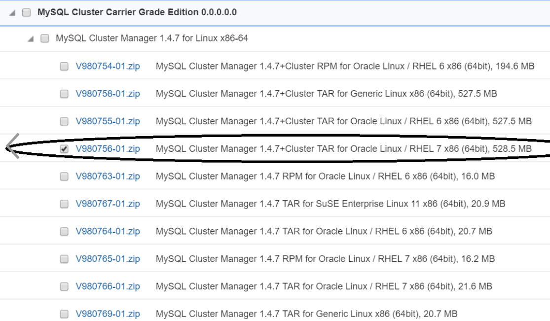
- View the download progress in Download manager, once download is completed, MySQL Cluster Manager software (V980756-01.zip) is downloaded. Once download is completed, V980756-01.zip file is used to install MySQL Cluster Manager 1.4.7(MCM) and MySQL NDB Cluster 7.6.8.
Oracle Linux 7.5 Download Instructions
The procedure to download Oracle Linux 7.5 is explained below:
- Login/Access https://edelivery.oracle.com Oracle Software Delivery Cloud (OSDC) page, to download Oracle Linux 7.5 ISO.
- Enter "Oracle Linux 7.5"
and click on
Search
"DLP: Oracle Linux 7.5.0.0.0 ( Oracle Linux ) " will be listed as shown below, click on Add to Cart.
- Click on Checkout, following page will be displayed.
- Select "Oracle Linux 7.5.0.0.0" and Select Platform as "x86-64 bit", Click on "Continue".
- Accept the licence agreement and click on "Continue".
-
Select "Oracle Linux Release 7 Update 5 for x86 (64 bit), 4.1 GB" as shown below and Click on "Download".
V975367-01.iso Oracle Linux Release 7 Update 5 for x86 (64 bit), 4.1 GBThis will install download manager and then provide the path where to download, download manager will download the Oracle Linux 7.5 software.

- View the download progress in Download manager, once download is completed, Oracle Linux 7.5(V975367-01.iso) is downloaded. Once the download is complete the Oracle Linux 7.5(V975367-01.iso) is used for installing host servers and VM creation.