5 Configuring Policy Control Function Using Cloud Native Core Console
This chapter describes how to configure different services in Oracle Communications Policy Control Function (PCF) and how to create policies and manageable objects in PCF using Oracle Communications Cloud Native Core Console.
Cloud Native Core Console Interface
This section provides an overview of the Oracle Communications Cloud Native Core (CNC) Console, which includes a interface to aid in creating policies and manageable objects in PCF.
- Open a web browser and enter the IP address of the CNC Console system.
The login page opens.
- Enter your Username.
- Enter your Password.
- Click Login.
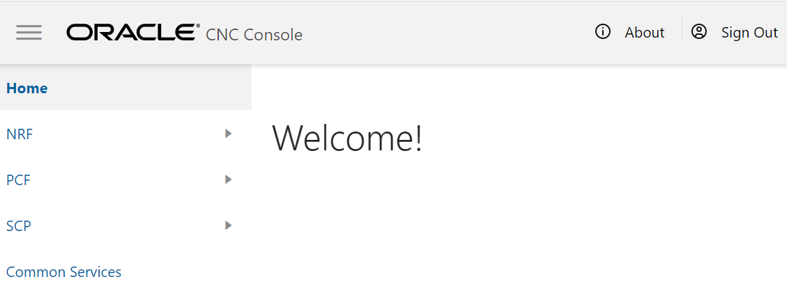
Tha main page opens.You are logged in. All the PCF related configurations are available in the left navigation menu under PCF.
Figure 5-1 CNC Console Interface
Configuring Services and Manageable Objects
This section describes how to create and manage the services and manageable objects that are available to be used in policies.
Service Configurations
You can tailor the PCF services as per network operator's requirements using the Service configuration pages. The configurations include setting up end point addresses, setting up log levels and other debug information like tracing etc. and customizing and/or optimizing NF interactions for example with UDR etc.
Note:
- The NAS Message Maximum Packet Size field is not supported in this release of PCF and will not take effect.
- The Validate User and Query User fields must always be set to false in this release of PCF.
Configuring Session Management Service
You can configure the session management service from this page.
- From the navigation menu,
under
PCF, then under
Service
Configurations, click
Session Management
Service.
The Session Management Service screen appears.
- Click Edit to edit the session management service configurations.
- Check the default
configuration for the fields available in respective groups and edit as
necessary.
The following table describes the input fields displayed under each group:
Field Name Description System Log Level
Indicates the log level of PCF Session Management (SM) service.
Default Value: WARN
Allowed Values: DEBUG, INFO, WARN, ERROR
Component Tracing
Determines if component tracing is enabled. Component tracing is used to evaluate system process latency in detail level.
Default Value: FALSE
FQDN
This is the PCF FQDN used by the PCF to register Binding data to BSF. AF may use this FQDN to communicate with PCF on N5 reference point.
Default Value: pcfsmservice.pcf
Diameter Realm
This is the PCF diameter realm used by the PCF to register Binding data to BSF. Diameter based AF may use this diameter realm to communicate with PCF on Rx reference point.
Default Value: pcf-smservice.svc
Diameter Identity
This is the PCF diameter identity used by the PCF to register Binding data to BSF. Diameter based AF may use this diameter identity to communicate with PCF on Rx reference point.
Default Value: pcf-smservice
Snssai
This is the PCF SNSSAI used by the PCF to register Binding data to BSF.
AF/BSF may use this SNSSAI to discover proper PCF.
Default Value: 0,000000
Enable Metrics
This determines if system metrics is enabled. This will take priority on global metrics configuration. Default Value: True Override Supported Features
Default Value: PRA User Validate User
Determines if user validate is enabled. HTTP 400 with cause USER_UNKNOWN returns, if this is enabled and user not found in UDR.
Default Value: FALSE
Query User
Determines if user query from UDR is enabled.
Default Value: TRUE
Query User On Update
Determines if user query from UDR on update is enabled.
Default Value : FALSE
Query User On Delete
Determines if user query from UDR on delete is enabled.
Default Value : FALSE
Query User On Reauth
Determines if user query from UDR on reauth is enabled.
Default Value : FALSE
Subscribe to Notify
Determines if subscribe to nofity about subscriber data change is enabled.
Default Value: TRUE
Ignore Subs Notification Check
Default Value: FALSE Enable CHF Query All
Default Value: FALSE Policy Evaluate This determines if policy evaluate is enabled.
Default Value: TRUE
Policy Control Request Trigger Default Policy Control Request Triggers
Values: PLMN_CH, UE_IP_CH, DEF_QOS_CH, and AC_TY_CH Binding Configuration Binding Operation
This determines if binding operation (register and deregister) to the BSF is enabled.
Default Value: TRUE
Binding Use Local Configured Bsf Always
Whether to use local configured BSF without Always discovering.
Default Value: FALSE
Binding Use Local Configured Bsf When Not Discovered
Whether to use local configured (if having) BSF when not discovered or discover failed.
Default Value: TRUE
Use HTTP2
Determines if using http/2 to communicate with BSF. Otherwise use http/1.1. Default Value : TRUE
QOS Qos Data Id Prefix
This is the prefix of qos data id used by PCF to generate qos data id. For example, prefix is "qosdata_", the generated qos data id is qosdata_0, chgdata_1, etc.
Default Value : qosdata_
update Default Pcf Rule With Auth Def Qos
This determines whether to update Qos of default PccRule with the authDefQos of session rule.
Default Value : TRUE
Install Default Qos If Not Requested
This determines whether to install default Qos to the PDU session if UE not requested. Default Value : TRUE
Default Qos 5qi
This is the 5Qi of default Qos which will be applied if no default Qos is requested by UE. Default Value: 9 Default Qos Arp Preempt Cap
This is the ARP PreemptionCapabi lity of default Qos which will be applied if no default Qos is requested by UE.
Default Value : MAY_PREEMPT
Default Qos Arp Preempt Vuln
This is the ARP PreemptionVulner ability of default Qos which will be applied if no default Qos is requested by UE.
Default Value : NOT_PREEMPTABLE
Default Qos Arp Priority Level
This is the ARP Priority Level of default Qos which will be applied if no default Qos is requested by UE. Default Value: 1
Rule Install Default Pcc Rule
Default Value : IF_NO_RULE Rule Id Prefix
Default Value : 0_ Default Pcc Rule 5qi
This is the 5Qi of default pcc rule. Default Value: 9
Default Pcc Rule Precedence
This is the precedence of default pcc rule.
Default Value : 3000
Default Pcc Rule Arp Preempt Cap
This is the ARP PreemptionCapabili ty of qos of default PCC rule.
Default Value : NOT_PREEMPT
Default Pcc Rule Arp Preempt Vuln
This is the ARP PreemptionVulnerability of qos of default pcc rule.
Default Value : PREEMPTABLE
App Rule Precedence Min
This value defines the minimum value for precedence of a PCC rule as authorized by the establishment of an application flow by the AF. If multiple rules are applied to the same packet flow or UE resource (i.e., overlapping rules) a rule with lower precedence value takes the priority over a rule with higher precedence value. The value of -1 is used to not set the precedence of a rule (NOT RECOMMENDED).
Default Value: 400
App Rule Precedence Max
This value defines the maximum value for precedence of a PCC rule as authorized by the establishment of an application flow by the AF. If multiple rules are applied to the same packet flow or UE resource (i.e., overlapping rules) a rule with lower precedence value takes the priority over a rule with higher precedence value. The value of -1 is used to not set the precedence of a rule (NOT RECOMMENDED).
Default Value: 899
Default Pcc Rule Arp Priority Level
This is the ARP Priority Level of qos of default pcc rule The range is 1 to 15. Values are ordered in decreasing order of priority, for example, with 1 as the highest priority and 15 as the lowest priority. Default Value : 15
Switch Flow In To Out Enabled
Default Value: FALSE
Charging Charging Data Id Prefix
Default Value: chgdata_
Primary CHF Address
Address of the primary CHF Secondary CHF Address
Address of the secondary CHF Online
Indicates the online charging is applicable to the PDU session. Offline
Indicates the offline charging is applicable to the PDU session. Traffic Control Traffic Control Id Prefix Default Value: tcdata_
IMS Emergency Session Emergency DNNs
Priority Level
Defines the relative importance of a resource request.
Default Value: 1
Preemption Capability
Defines whether a service data flow may get resources that were already assigned to another service data flow with a lower priority level. Default Value: MAY_PREEMPT
Preemption Vulnerability
Defines whether a service data flow may lose the resources assigned to it in order to admit a service data flow with higher priority level. Default Value: NOT_PREEMPTABLE
- Click Save.
Configuring Access and Mobility Service
You can configure the access and mobility service from this page.
- From the navigation menu,
under
PCF, then under
Service
Configurations, click
Access and Mobility
Service.
The Access and Mobility Service screen appears.
- Click Edit to edit the access and mobility service configurations.
- Check the default
configuration for all the fields in all groups and edit as necessary
The following table describes the input fields available under each group:
Field Name Description System Root Log Level Default Value: WARN
Log Level Use Policy Service
Default Value: true
Use User Service
Default Value: true
Subscribe
Default Value: true
Enable HTTP2.0
Default Value: false
Validate User
Determines if user validate is enabled. HTTP 400 with cause USER_UNK NOWN returns, if this is enabled and user not found in UDR.
Default Value: false
App Default Service Area Restriction
Default Rfsp
Default Triggers
- Click Save.
Configuring User Service
You can configure the user service from this page.
- From the navigation menu,
under
PCF, then under
Service
Configurations, click
User Service.
The User Service screen appears.
- Click Edit to edit the user service configurations.
- In the Server Root URL field, enter the callback URI for notifications to be received by the User service (For example, while creating a subscription for the user with the UDR)
- Check the default
configuration for all the fields in all groups and edit as necessary.
The following table describes the input fields displayed under each group:
Field Name Description System Log Level
Default Value: WARN Server Root URL
Common Resource Get Subscribe
Default Value: false Request Timeout
Default Value: 1000 DB Keys Precedence
User Index Keys
Indexing Index By Msisdn
Default Value: true Index By Extid
Default Value: true Index By Imsi
Default Value: true Index By Nai
Default Value: true UDR Base Uri
Default Value: /nudr-dr/v1 Supported Features
Default Value: f AM Data Uri
Default Value: /policy-data/ues/{ueId}/am-data UE Policy Set Uri
Default Value: /policy-data/ues/{ueId}/ue-policy-set SM Data Uri
Default Value: /policy-data/ues/{ueId}/sm-data Usage Mon Uri
Default Value: /policy-data/ues/{ueId}/sm-data/{usageMonId} Subs To Notify Uri
Default Value: /policy-data/subs-to-notify Subs To Notify Subs Id Uri
Default Value: /policy-data/subs-to-notify/{subsId} Request Timeout
Default Value: 1000 Explode Snssai
Default Value: false Enable HTTP1.1
Default Value: false Enable Discovery On Demand
Default Value: true - Click Save.
Configuring Policy Authorization Service
You can configure the policy authorization service from this page.
- From the navigation menu,
under
PCF, then under
Service
Configurations, click
Policy Authorization
Service.
The Policy Authorization Service screen appears.
- Click Edit to edit the policy authorization service configurations.
- Check the default
configuration for all the fields in all groups and edit as necessary.
The following table describes the input fields displayed under each group:
Field Name Description System Af Direct Reply
Default Value: true Override Supported Features
AF Terminate Uri Segment
Default Value: termination AF Subscriber Notify Segment
Default Value: termination IMS Emergency Session Emergency Service URNs
Reservation Priority Types
Default Value: PRIO_6 - Click Save.
Configuring UE Policy Service
You can configure the UE policy service from this page.
- From the navigation menu,
under
PCF, then under
Service
Configurations, click
UE Policy
Service.
The UE Policy Service screen appears.
- Click Edit to edit the UE policy service configurations.
- In the Notification URI Root field, enter the callback URI for notifications to be received by the UE Policy service (For example, while creating a subscription for the NAS Message Transfer with the AMF)
- Check the default
configuration for all the fields in all groups and edit as necessary.
The following table describes the input fields displayed under each group:
Field Name Description System Log Level
Default Value: WARN Notification URI Root
AMF Enable HTTP/1.1
Default Value: false NAS Message Maximum Packet Size (bytes)
enter a range in [0-65535] number User Validate User
Default Value: false Query User
Default Value: false - Click Save.
Policy Configurations
This chapter describes how to create manageable objects in Policy Control Function (PCF).
Common
You can configure the common services from this page. To configure the common service, navigate to PCF, then under Policy Configurations, click Common.
The Common configuration includes Managing Presence Reporting Area.
Managing Presence Reporting Area
You can manage, view, import, export and create the Presence Reporting Area from Pra Management screen.
Note:
Only administrators can create presence reporting area.To configure the service:
- From the navigation menu,
under
Policy
Configurations, then under
Common, click
Presence Reporting
Area.
The Pra Management screen appears with the listing of all the available reports. You can create or import new reports from this page.
Note:
Click Export to download the available reports to your system. - Click
Add.
The Create Pra screen appears.
- On the
Create Pra
screen, enter values for the input fields common to all the groups available on
the screen. .
The following table describes the fields:
Field Name Description Name The unique name assigned to the PRA. Pra Id The unique identifying number of the PRA list. The ID must be numeric value between 0 and 16777125. This field is present if the Area of Interest subscribed or reported is a Presence Reporting Area. Presence State Indicates whether the UE is inside or outside of the area of interest (e.g presence reporting area or the LADN area), or if the presence reporting area is inactive in the serving node.
Select any one of the following values:- IN_AREA : Indicates that the UE is inside or enters the presence reporting area.
- OUT_OF_AREA : Indicates that the UE is outside or leaves the presence reporting area.
- UNKNOWN : Indicates it is unknown whether the UE is in the presence reporting area or not.
- INACTIVE : Indicates that the presence reporting area is inactive in the serving node.
- Expand the
Tracking Area
List group.
The expanded window displays the available tracking area lists. To create new lists:
- Click
Add.
The Add Tracking Area List window appears on the screen.
- Enter the applicable
values in the input fields available on the window.
The following table describes the fields:
Field Name Description Mnc Defines the Mobile Network Code. Two to three digit number. Mcc Defines the Mobile Country Code. Three digit number. Tac 28-bit string identifying an E-UTRA Cell Id as specified, in hexadecimal representation. Each character in the string shall take a value of "0" to "9" or "A" to "F" and shall represent 4 bits. The most significant character representing the 4 most significant bits of the Cell Id shall appear first in the string, and the character representing the 4 least significant bit of the Cell Id shall appear last in the string. Pattern: '^[A-Fa-f0-9]{7}$'
Example:
An E-UTRA Cell Id 0x5BD6007 shall be encoded as "5BD6007".
Note:
Click Cancel to cancel the changes. - Click
Save.
The value gets listed in the Tracking Area List.
Note:
Use Edit or Delete buttons available in the next column to update or delete the listing.
- Click
Add.
- Expand the
Ecgi List group.
The expanded window displays the available Eutra Cell Ids. To create new Ids:
- Click
Add.
The Add Ecgi List window appears on the screen.
- Enter the applicable
values in the input fields available on the window.
The following table describes the fields:
Field Name Description Mnc Defines the Mobile Network Code of the PLMN. Two to three digit number. Mcc Defines the Mobile Country Code of the PLMN. Three digit number. Eutra Cell Id 28-bit string identifying an E-UTRA Cell Id as specified in hexadecimal representation. Each character in the string shall take a value of "0" to "9" or "A" to "F" and shall represent 4 bits. The most significant character representing the 4 most significant bits of the Cell Id shall appear first in the string, and the character representing the 4 least significant bit of the Cell Id shall appear last in the string.
Pattern: '^[A-Fa-f0-9]{7}$'
Example:
An E-UTRA Cell Id 0x5BD6007 shall be encoded as "5BD6007".
Note:
Click Cancel to cancel the changes. - Click
Save.
The value gets listed in the Ecgi List.
Note:
Use Edit or Delete buttons available in the next column to update or delete the listing.
- Click
Add.
- Expand the
Ncgi List group.
The expanded window displays the available Nr Cell Ids. To create new Ids:
- Click
Add.
The Add Ncgi List window appears on the screen.
- Enter the applicable
values in the input fields available on the window.
The following table describes the fields:
Field Name Description Mnc Defines the Mobile Network Code of the PLMN. Two to three digit number. Mcc Defines the Mobile Country Code of the PLMN. Three digit number. Nr Cell Id 36-bit string identifying an NR Cell Id as specified in hexadecimal representation. Each character in the string shall take a value of "0" to "9" or "A" to "F" and shall represent 4 bits. The most significant character representing the 4 most significant bits of the Cell Id shall appear first in the string, and the character representing the 4 least significant bit of the Cell Id shall appear last in the string.
Pattern: '^[A-Fa-f0-9]{9}$'
Example:
An NR Cell Id 0x225BD6007 shall be encoded as "225BD6007".
Note:
Click Cancel to cancel the changes. - Click
Save.
The value gets listed in the Ncgi List.
Note:
Use Edit or Delete buttons available in the next column to update or delete the listing.
- Click
Add.
- Expand the
Global Ran NodeId
List group.
The expanded window displays the available N3 lwf Ids. To create new Ids:
- Click
Add displayed
in the window.
The Add Global Ran NodeId List window appears on the screen.
- Enter the applicable
values in the input fields available on the window.
The following table describes the fields:
Field Name Description Plmn Id Mnc Defines the Mobile Network Code of the PLMN. Two to three digit number. Mcc Defines the Mobile Country Code of the PLMN. Three digit number. N3 lwf Id This field is included if the RAN node belongs to non 3GPP access (i.e a N3IWF).
If included, this field contains the FQDN of the N3IWF.
gNb Id Bit Length Unsigned integer representing the bit length of the gNB ID within the range 22 to 32
gNb Value This represents the identifier of the gNB.
The string shall be formatted with following pattern:
'^[A-Fa-f0-9]{6,8}$'
The value of the gNB ID shall be encoded in hexadecimal representation. Each character in the string shall take a value of "0" to "9" or "A" to "F" and shall represent 4 bits. The most significant character representing the 4 most significant bits of the gNB ID shall appear first in the string, and the character representing the 4 least significant bit of the gNB ID shall appear last in the string.
Examples:
"382A3F47" indicates a gNB ID with value 0x382A3F47
Nge Nb Id This field is included if the RAN Node Id represents a NG-eNB. When present, this field contains the identifier of an NG-eNB. Note:
Click Cancel to cancel the changes. - Click
Save.
The value gets listed under Global Ran NodeId List.
Note:
Use Edit or Delete buttons available in the next column to update or delete the listing.
- Click
Add displayed
in the window.
- Click
Save.
The Pra details are listed on the Presence Reporting Area screen.
Note:
Click Cancel to cancel the configuration.
Importing the Presence Reports
To import the reports:
- Click
Import.
The File Upload window appears on the screen.
- Upload the files in required format by clicking Drop Files here or click to upload button.
SM Policy
You can configure the SM Policy from this page. To configure the SM Policy, navigate to PCF, then under Policy Configurations, click SM Policy.
The SM Policy configurations includes:
Managing Session Rule
You can create and manage session rules from the Session Rule Management screen. The page provides information about the existing session rules. You can create or refresh the session rules from this page.
Note:
Only administrators can create session rules.To configure the session rules from this page:
- From the navigation menu,
under
Policy
Configurations, then under
SM Policy, click
Session Rule.
The Session Rule Management screen appears with the listing of all the available rules. You can create or import new rules details from this page.
Note:
Click the Export button to download the available listings to your system. - Click
Add.
The Create Session Rule screen appears.
- On the
Create Session
Rule screen, enter values for the input fields common to all the groups
available on the screen.
The following table describes the fields:
Field Name Description ID Specifies the Session Rule ID. NAME Specifies the name assigned to the session rule. Description Free-form text that identifies the session rule. - Expand the
Authorized Session
AMBR group to add the AMBR details:
- Click Add displayed in the window.
- Enter the applicable
values in the input fields available on the window.
The following table describes the fields:
Field Name Description Uplink Bandwidth Specifies the bandwidth in uplink. Downlink Bandwidth Specifies the bandwidth in downlink. Note:
Click Remove to cancel the changes.
- Select value for
Authorize Default
Qos from the drop down menu.
Note:
The drop down gets its data from the QoS Information created.Note:
Click Cancel to cancel the configuration. - Click
Save.
The value gets listed on the Session Rule Management screen.
Note:
Use Edit or Delete buttons available in the next column to update or delete the listing.
Importing the Session Rules
To import the session rules:
- Click
Import.
The File Upload window appears on the screen.
- Upload the files in required format by clicking Drop Files here or click to upload.
Managing Session Rule Profile
You can manage and configure the session rule profiles from this page.
To configure the profile:
- From the navigation menu,
under
Policy
Configurations, then under
SM Policy, click
Session Rule
Profile.
The Session Rule Profile Management screen appears with the listing of all the available rules. You can create or import new profiles from this page.
Note:
Click Export to download the available listings to your system. - Click
Add.
The Create Session Rule Profile screen appears.
- On the
Create Session Rule
Profile screen, enter values for the input fields common to all the groups
available on the screen.
The following table describes the fields:
Field Name Description Session Rule Profile NAME Specifies the name assigned to the session rule profile. Description Free-form text that identifies the session rule profile. - Expand the
Authorized Session
AMBR group to add the AMBR details:
- Click Add displayed in the window.
- Enter the applicable
values in the input fields available on the window.
The following table describes the fields:
Field Name Description Uplink Bandwidth Specifies the bandwidth in uplink. Downlink Bandwidth Specifies the bandwidth in downlink. Note:
Click Remove to cancel the changes.
- Select value for Condition Data from the drop down menu.
- Select value for
Authorize Default
Qos from the drop down menu.
Note:
Click Cancel to cancel the configuration. - Click
Save.
The value gets listed on the Session Rule Profile Management screen.
Note:
Use Edit or Delete buttons available in the next column to update or delete the listing.
Importing the Session Rule Profiles
To import the session rule profiles:
- Click
Import.
The File Upload window appears on the screen.
- Upload the files in required format by clicking Drop Files here or click to upload button.
Managing QoS Information
You can manage, view, import, export and create the QoS Information from QoS Information Management screen.
Note:
Only administrators can create QoS Information data.To configure the QoS Information data:
- From the navigation menu, under Policy Configurations, then
under SM Policy, click QoS Information.
The Authorized Default QoS Management screen appears with the listing of all the available rules. You can create or import the QoS details from this page.
Note:
Click Export to download the available listings to your system. - Click Add.
The Create Authorized Default QoS screen appears.
- On the Create Authorized Default QoS
screen, enter values for the input fields common to all the groups available on the
screen.
The following table describes the fields:
Field Name Description Name Specifies the name assigned to the QOS information. Description Free-form text that identifies the QOS information. Default 5G QoS Identifier Identifier for the authorized QoS parameters for the service data flow. It shall be included when the QoS information decision is initially provisioned. Priority Level Unsigned integer indicating the 5QI Priority Level, within a range of 1 to 127. Average Window Represents the duration over which the guaranteed and maximum bitrate shall be calculated (NOTE). Max DataBurstVol Denotes the largest amount of data that is required to be transferred within a period of 5GAN PDB (NOTE). - Expand the
arp group to add
the arp details:
- Enter the applicable
values in the input fields available on the window.
The following table describes the fields:
Field Name Description Priority Level Unsigned integer indicating the ARP Priority Level, within the range 1 to 15. Preemption Capability Defines whether a service data flow may get resources that were already assigned to another service data flow with a lower priority level. Possible values are: - NOT_PREEMPT : Shall not trigger pre-emption.
- MAY_PREEMPT : May trigger pre-emption.
Preemption Vulnerability Defines whether a service data flow may lose the resources assigned to it in order to admit a service data flow with higher priority level. Possible values are: - NOT_PREEMPTABLE : Shall not be pre-empted.
- PREEMPTABLE : May be pre-empted.
Note:
Click the Remove button to cancel the changes. - Click the
ADD button to
add the changes.
Note:
Click Cancel to cancel the configuration.
- Enter the applicable
values in the input fields available on the window.
- Click Save.
The value gets listed on the Authorized Default QoS Management screen.
Note:
Use Edit or Delete buttons available in the next column to update or delete the listing.
Importing the QoS Information
To import the session rules:
- Click
Import.
The File Upload window appears on the screen.
- Upload the files in required format by clicking Drop Files here or click to upload button.
Managing PCC Rule
You can create and manage PCC Rule from the PCC Rule Management screen. The page provides information about the existing rules. You can create or refresh the PCC rules from this page.
Note:
Only administrators can create PCC rules.To configure the rule:
- From the navigation menu,
under
Policy
Configurations, then under
SM Policy, click
PCC Rule.
The PCC Rule Management screen appears with the listing of all the available rules. You can create or import new rules details from this page.
Note:
Click Export to download the available listings to your system. - Click
Add.
The Create PCC Rule screen appears.
- On the
Create PCC Rule
screen, enter values for the input fields common to all the groups available on
the screen.
The following table describes the fields:
Field Name Description PCC Rule Id Specifies the PCC Rule ID. Name Specifies the name assigned to the PCC rule. Description Free-form text that identifies the PCC rule. Type Select the required type. Possible Values are: - Expand the
Flow Infos group
to add the Flow information:
- Click the
Add icon
displayed in the window.
The Add Flow Infos appears.
- Enter the applicable
values in the input fields available on the window.
The following table describes the fields:
Field Name Description Name
Indicates the name for the flow. Flow Description
Indicates the details about flow. Enter a description for the flow.
Pack Filt Id
An identifier of packet filter. Packet Filter Usage
The packet shall be sent to the UE. The default value "FALSE" shall apply, if the attribute is not present and has not been supplied previously. Tos Traffic Class
Contains the Ipv4 Type-of-Service and mask field or the Ipv6 Traffic-Class field and mask field. Spi The security parameter index of the IPSec packet. Flow Label
The Ipv6 flow label header field. Flow Direction
Indicates the flow direction. Select from the following options:
- DOWNLINK
- UPLINK
- BIDIRECTIONAL
- UNSPECIFIED
Ethernet Flow Description Dest Mac Address
A string indicating MAC address. Enter a valid MAC address. For example, 3D-F2-C9-A6-B3-4F Ethernet Type
A two-octet string that represents the Ethertype, in hexadecimal representation. Each character in the string shall take a value of "0" to "9" or "A" to "F" and shall represent 4 bits. The most significant character representing the 4 most significant bits of the ethType shall appear first in the string, and the character representing the 4 least significant bits of the ethType shall appear last in the string.
Flow Description
Indicates the details about flow. Enter a description for the flow. Flow Direction
Indicates the flow direction. Select from the following options:
- DOWNLINK
- UPLINK
- BIDIRECTIONAL
- UNSPECIFIED
Source Mac Address
Enter a MAC Address. For example, 3D-F2-C9-A6-B3-4F Vlan Tags
Customer-VLAN and/or Service-VLAN tags containing the VID, PCP/DEI fields. Each field is encoded as a two-octet string in hexadecimal representation. Each character in the string shall take a value of "0" to "9" or "A" to "F" and shall represent 4 bits. The most significant character representing the 4 most significant bits of the VID or PCF/DEI field shall appear first in the string, and the character representing the 4 least significant bits of the VID or PCF/DEI field shall appear last in the string.
- Click
Add under the
Ethernet Flow
Description group name to expand the group.
The screen displays the available input fields. Enter the applicable values in the input fields.
The following table describes the fields:
Field Name Description Dest Mac Address
A string indicating MAC address. Enter a valid MAC address. For example, 3D-F2-C9-A6-B3-4F Ethernet Type
A two-octet string that represents the Ethertype, in hexadecimal representation. Each character in the string shall take a value of "0" to "9" or "A" to "F" and shall represent 4 bits. The most significant character representing the 4 most significant bits of the ethType shall appear first in the string, and the character representing the 4 least significant bits of the ethType shall appear last in the string.
Flow Description
Indicates the details about flow. Enter a description for the flow. Flow Direction
Indicates the flow direction. Select from the following options:
- DOWNLINK
- UPLINK
- BIDIRECTIONAL
- UNSPECIFIED
Source Mac Address
Enter a MAC Address. For example, 3D-F2-C9-A6-B3-4F Vlan Tags
Customer-VLAN and/or Service-VLAN tags containing the VID, PCP/DEI fields. Each field is encoded as a two-octet string in hexadecimal representation. Each character in the string shall take a value of "0" to "9" or "A" to "F" and shall represent 4 bits. The most significant character representing the 4 most significant bits of the VID or PCF/DEI field shall appear first in the string, and the character representing the 4 least significant bits of the VID or PCF/DEI field shall appear last in the string.
Note:
Click Remove to cancel the changes. - Click
Save on the
Add Flow
Infos window, under the
Flow Infos
group.
The value gets listed on the Create PCC Rule screen
- Under the
Flow Infos
group, enter values for the rest of the input fields:
Field Name Description App Id
A reference to the application detection filter configured at the UPF. Content Version
Indicates the content version of the PCC rule. Precedence
Determines the order in which this PCC rule is applied relative to other PCC rules within the same PDU session. It shall be included if the "flowInfos" attribute is included or may be included if the "appId" attribute is included when the PCF initially provisions the PCC rule. AF Signalling Protocol
Indicates the protocol used for signalling between the UE and the AF. The default value "NO_INFORMATION" shall apply, if the attribute is not present and has not been supplied previously. Application Relocation
Indication of application relocation possibility. The default value "NO_INFORMATION" shall apply, if the attribute is not present and has not been supplied previously. Qos Data
A reference to the QoSData policy type decision type. Traffic Control Data
A reference to the TrafficControlData policy decision type. Charging Data
A reference to the ChargingData policy decision type. Usage Monitoring Data
A reference to UsageMonitoringData policy decision type. Condition Data
A reference to the condition data.
- Click the
Add icon
displayed in the window.
- Click
Save.
The value gets listed on the PCC Rule Management screen.
Note:
Use Edit or Delete buttons available in the next column to update or delete the listing.
Importing the PCC Rules
To import the session rules:
- Click
Import.
The File Upload window appears on the screen.
- Upload the files in required format by clicking Drop Files here or click to upload.
Managing PCC Rule Profile
You can create and manage PCC Rule Profile from the PCC Rule Profile Management screen. The page provides information about the existing profiles. You can create or refresh the profiles from this page.
Note:
Only administrators can create PCC Rule Profile.To configure the PCC Rule Profile:
- From the navigation menu,
under
Policy
Configurations, then under
SM Policy, click
PCC Rule Profile.
The PCC Rule Profile Management screen appears with the listing of all the available rules. You can create or import new profile details from this page.
Note:
Click the Export button to download the available listings to your system. - Click
Add.
The Create PCC Rule Profile screen appears.
- On the
Create PCC Rule
Profile screen, enter values for the input fields common to all the groups
available on the screen.
The following table describes the fields:
Field Name Description Name Specifies the name assigned to the PCC rule profile. Description Free-form text that identifies the PCC rule profile. Type Select the required type. Possible Values are: - Predefined PCC Rule
- Dynamic PCC Rule
If you have selected Dynamic PCC Rule, then go to Step 4 else, go to Step 5.
- Expand the
Flow Infos group
to add the Flow information:
- Click the
Add icon
displayed in the window.
The Add Flow Infos appears.
- Enter the applicable
values in the input fields available on the window.
The following table describes the fields:
Field Name Description Name
Indicates the name for the flow. Flow Description
Indicates the details about flow. Enter a description for the flow.
Pack Filt Id
An identifier of packet filter. Packet Filter Usage
The packet shall be sent to the UE. The default value "FALSE" shall apply, if the attribute is not present and has not been supplied previously. Tos Traffic Class
Contains the Ipv4 Type-of-Service and mask field or the Ipv6 Traffic-Class field and mask field. Spi The security parameter index of the IPSec packet. Flow Label
The Ipv6 flow label header field. Flow Direction
Indicates the flow direction. Select from the following options:
- DOWNLINK
- UPLINK
- BIDIRECTIONAL
- UNSPECIFIED
Ethernet Flow Description Dest Mac Address
A string indicating MAC address. Enter a valid MAC address. For example, 3D-F2-C9-A6-B3-4F Ethernet Type
A two-octet string that represents the Ethertype, in hexadecimal representation. Each character in the string shall take a value of "0" to "9" or "A" to "F" and shall represent 4 bits. The most significant character representing the 4 most significant bits of the ethType shall appear first in the string, and the character representing the 4 least significant bits of the ethType shall appear last in the string.
Flow Description
Indicates the details about flow. Enter a description for the flow. Flow Direction
Indicates the flow direction. Select from the following options:
- DOWNLINK
- UPLINK
- BIDIRECTIONAL
- UNSPECIFIED
Source Mac Address
Enter a MAC Address. For example, 3D-F2-C9-A6-B3-4F Vlan Tags
Customer-VLAN and/or Service-VLAN tags containing the VID, PCP/DEI fields. Each field is encoded as a two-octet string in hexadecimal representation. Each character in the string shall take a value of "0" to "9" or "A" to "F" and shall represent 4 bits. The most significant character representing the 4 most significant bits of the VID or PCF/DEI field shall appear first in the string, and the character representing the 4 least significant bits of the VID or PCF/DEI field shall appear last in the string.
- Click
Add under the
Ethernet Flow
Description group name to expand the group.
The screen displays the available input fields. Enter the applicable values in the input fields.
The following table describes the fields:
Field Name Description Dest Mac Address
A string indicating MAC address. Enter a valid MAC address. For example, 3D-F2-C9-A6-B3-4F Ethernet Type
A two-octet string that represents the Ethertype, in hexadecimal representation. Each character in the string shall take a value of "0" to "9" or "A" to "F" and shall represent 4 bits. The most significant character representing the 4 most significant bits of the ethType shall appear first in the string, and the character representing the 4 least significant bits of the ethType shall appear last in the string.
Flow Description
Indicates the details about flow. Enter a description for the flow. Flow Direction
Indicates the flow direction. Select from the following options:
- DOWNLINK
- UPLINK
- BIDIRECTIONAL
- UNSPECIFIED
Source Mac Address
Enter a MAC Address. For example, 3D-F2-C9-A6-B3-4F Vlan Tags
Customer-VLAN and/or Service-VLAN tags containing the VID, PCP/DEI fields. Each field is encoded as a two-octet string in hexadecimal representation. Each character in the string shall take a value of "0" to "9" or "A" to "F" and shall represent 4 bits. The most significant character representing the 4 most significant bits of the VID or PCF/DEI field shall appear first in the string, and the character representing the 4 least significant bits of the VID or PCF/DEI field shall appear last in the string.
Note:
Click Remove to cancel the changes. - Click
Save on the
Add Flow
Infos window, under the
Flow Infos
group.
The value gets listed on the Create PCC Rule screen
- Under the
Flow Infos
group, enter values for the rest of the input fields:
Field Name Description App Id
A reference to the application detection filter configured at the UPF. Content Version
Indicates the content version of the PCC rule. Precedence
Determines the order in which this PCC rule is applied relative to other PCC rules within the same PDU session. It shall be included if the "flowInfos" attribute is included or may be included if the "appId" attribute is included when the PCF initially provisions the PCC rule. AF Signalling Protocol
Indicates the protocol used for signalling between the UE and the AF. The default value "NO_INFORMATION" shall apply, if the attribute is not present and has not been supplied previously. Application Relocation
Indication of application relocation possibility. The default value "NO_INFORMATION" shall apply, if the attribute is not present and has not been supplied previously. Qos Data
A reference to the QoSData policy type decision type. Traffic Control Data
A reference to the TrafficControlData policy decision type. Charging Data:
A reference to the ChargingData policy decision type. Usage Monitoring Data
A reference to UsageMonitoringData policy decision type. Condition Data
A reference to the condition data.
- Click the
Add icon
displayed in the window.
- Click
Save.
The value gets listed on the PCC Rule Profile Management screen.
Note:
Use Edit or Delete buttons available in the next column to update or delete the listing.
Importing the PCC Rule Profiles
To import the session rules:
- Click
Import.
The File Upload window appears on the screen.
- Upload the files in required format by clicking Drop Files here or click to upload.
Managing QoS Data
You can create and manage QoS Data from the Session Rule Management screen. The page provides information about the existing QoS Data. You can create or refresh the QoS Data from this page.
Note:
Only administrators can create QoS Data.To configure the QoS Data:
- From the navigation menu, under Policy Configurations, then
under SM Policy, click QoS Data.
The QoS Data Management screen appears with the listing of all the available rules. You can create or import new rules details from this page.
Note:
Click Export to download the available listings to your system. - Click
Add.
The Create Qos Data screen appears.
- On the Create QoS Data screen, enter
values for the input fields common to all the groups available on the screen.
The following table describes the fields:
Field Name Description QoS ID Specifies the QoS ID. Name
Specifies the name assigned to the QOS data. Description
Free-form text that identifies the QOS data. Default 5G QoS Identifier
Identifier for the authorized QoS parameters for the service data flow. It shall be included when the QoS data decision is initially provisioned. Maximum Bit Rate UL
Indicates the max bandwidth in uplink. Maximum Bit Rate DL
Indicates the max bandwidth in downlink. Guaranteed Bit Rate UL
Indicates the guaranteed bandwidth in uplink Guaranteed Bit Rate DL
Indicates the guaranteed bandwidth in downlink. QoS Notification Control
Reflective QoS
Indicates whether the QoS information is reflective for the corresponding service data flow. Default value is "FALSE", if not present and has not been supplied previously.
Sharing Key Ul
Indicates, by containing the same value, what PCC rules may share resource in uplink direction. Sharing Key Dl
Indicates, by containing the same value, what PCC rules may share resource in downlink direction. Priority Level
Defines the relative importance of a resource request. Averaging Window
Represents the duration over which the guaranteed and maximum bitrate shall be calculated (NOTE). Maximum Data Burst Volume
Denotes the largest amount of data that is required to be transferred within a period of 5GAN PDB (NOTE). Maximum Packet Loss Rate Dl
Indicates the uplink maximum rate for lost packets that can be tolerated for the service data flow. Max Packet Loss Rate Ul
Indicates the uplink maximum rate for lost packets that can be tolerated for the service data flow. Default QoS Flow Indication
Indicates that the dynamic PCC rule shall always have its binding with the QoS Flow associated with the default QoS rule. Default value is "FALSE", if not present and has not been supplied previously.
- Expand the ARP group to add the arp
details:
- Enter the applicable values in the
input fields available on the window.
The following table describes the fields:
Field Name Description Priority Level Defines the relative importance of a resource request. Preemption Capability Defines whether a service data flow may get resources that were already assigned to another service data flow with a lower priority level. Possible values are: - NOT_PREEMPT
- MAY_PREEMPT
Preemption Vulnerability Defines whether a service data flow may lose the resources assigned to it in order to admit a service data flow with higher priority level. Possible values are: - NOT_PREEMPTABLE
- PREEMPTABLE
Note:
Click the Remove button to cancel the changes. - Click the ADD button to add the
changes.
Note:
Click Cancel to cancel the configuration.
- Enter the applicable values in the
input fields available on the window.
- Click Save.
The value gets listed on the QoS Data Management screen.
Note:
Use Edit or Delete buttons available in the next column to update or delete the listing.
Importing the QoS Data
To import the QoS Data:
- Click
Import.
The File Upload window appears on the screen.
- Upload the files in required format by clicking Drop Files here or click to upload button.
Managing Charging Data
You can manage, view, import, export and create the Charging Data from Charging Data Management screen.
Note:
Only administrators can create Charging data.To configure the service:
- From the navigation menu,
under
Policy
Configurations, then under
SM Policy, click
Charging Data.
The Charging Data Management screen appears with the listing of all the available rules. You can create or import new data from this page.
Note:
Click Export to download the available listings to your system. - Click
Create.
The Create Charging Data screen appears.
- On the
Create Charging
Data screen, enter values for the input fields common to all the groups
available on the screen.
The following table describes the fields:
Field Name Description Charging id Specifies the charging id. Name
The name of the Charging Data. Description
The description of the Charging Data. Metering Method
The following options are available
- DURATION
- VOLUME
- DURATION_VOLUME
- EVENT
Defines what parameters shall be metered for offline charging. If the attribute is not present but it has been supplied previously, the previous information remains valid. If the attribute is not present and it has not been supplied previously or the attribute has been supplied previously but the attribute is set to NULL, the metering method preconfigured at the SMF is applicable as default metering method.
Offline
Indicates the offline charging is applicable to the PDU session or PCC rule. The default value "FALSE" shall apply, if the attribute is not present and has not been supplied previously. (NOTE)
Online
Indicates the online charging is applicable to the PDU session or PCC rule. The default value "FALSE" shall apply, if the attribute is not present and has not been supplied previously. (NOTE)
Rating Group
The charging key for the PCC rule used for rating purposes. Reporting Level
The following options are available:
- SER_ID_LEVEL
- RAT_GR_LEVEL
- SPON_CON_LEVEL
Defines on what level the SMF reports the usage for the related PCC rule. If the attribute is not present but it has been supplied previously, the previous information remains valid. If the attribute is not present and it has not been supplied previously or the attribute has been supplied previously but it is set to NULL, the reporting level preconfigured at the SMF is applicable as default reporting level.
Service Id
Indicates the identifier of the service or service component the service data flow in a PCC rule relates to. Sponsor Id
Indicates the sponsor identity. App Svc Prov Id
Indicates the application service provider identity. Af Charging Identifier
Univocally identifies the charging control policy data within a PDU session. Note:
Click Cancel to cancel the configuration. - Click
Save.
The value gets listed on the Charging Data Management screen.
Note:
Use Edit or Delete buttons available in the next column to update or delete the listing.
Importing the Charging Data
To import the session rules:
- Click
Import.
The File Upload window appears on the screen.
- Upload the files in required format by clicking Drop Files here or click to upload.
Managing Usage Monitoring Data
You can create and manage Usage Monitoring Data from the Session Rule Management screen. The page provides information about the existing Usage Monitoring Data. You can create or refresh the Usage Monitoring Data from this page.
Note:
Only administrators can create Usage Monitoring Data.To configure the service:
- From the navigation menu,
under
Policy
Configurations, then under
SM Policy, click
Usage Monitoring
Data.
The Usage Monitoring Data Management screen appears with the listing of all the available rules. You can create or import new rules details from this page.
Note:
Click Export to download the available listings to your system. - Click
Add.
The Create Usage Monitoring Data screen appears.
- On the
Create Usage
Monitoring Data screen, enter values for the input fields common to all the
groups available on the screen.
The following table describes the fields:
Field Name Description Usage Monitoring id Specifies the usage monitoring id. Name
The name of the Usage Monitoring Data.
Description
The description of the Usage Monitoring Data. Volume Threshold
Indicates a volume threshold. Volume Threshold Uplink
Indicates a volume threshold in uplink. Volume Threshold Downlink
Indicates a volume threshold in downlink. Time Threshold
Indicates a time threshold. Monitoring Time
Indicates the time at which the UP function is expected to reapply the next thresholds (e.g. nextVolThreshold). Next Vol Threshold
Indicates a volume threshold after the Monitoring. Next Vol Threshold Uplink
Indicates a volume threshold in uplink after the Monitoring Time. Next Vol Threshold Downlink
Indicates a volume threshold in downlink after the Monitoring Time. Next Time Threshold
Indicates a time threshold after the Monitoring. Inactivity Time
Defines the period of time after which the time measurement shall stop, if no packets are received. ex Usage PccRule Ids
Contains the PCC rule identifier(s) which corresponding service data flow(s) shall be excluded from PDU Session usage monitoring. It is only included in the UsageMonitoringData instance for session level usage monitoring.
Note:
Click Cancel to cancel the configuration. - Click
Save.
The value gets listed on the Usage Monitoring Data Management screen.
Note:
Use Edit or Delete buttons available in the next column to update or delete the listing.
Importing the Usage Monitoring Data
To import the Usage Monitoring Data:
- Click
Import.
The File Upload window appears on the screen.
- Upload the files in required format by clicking Drop Files here or click to upload.
Managing Traffic Control Data
You can manage, view, import, export and create the Traffic Control Data from Traffic Control Data Management screen.
Note:
Only administrators can create traffic control data.To configure the traffic control data:
- From the navigation menu,
under
Policy
Configurations, then under
SM Policy, click
Traffic Control
Data.
The Traffic Control Data Management screen appears with the listing of all the available rules. You can create or import new data from this page.
Note:
Click Export to download the available listings to your system. - Click
Add.
The Create Traffic Control Data screen appears.
- On the
Create Traffic
Control Data screen, enter values for the input fields common to all the
groups available on the screen.
The following table describes the fields:
Field Name Description Traffic Control id Specifies the traffic control policy data id. Name
The name of the Traffic Control policy data. Description
The description of the Traffic Control policy data. Flow Status
The following options are available:- ENABLED-UPLINK
- ENABLED-DOWNLINK
- ENABLED
- DISABLED
- REMOVED
Enum determining what action to perform on traffic.
Possible values are: [enable, disable, enable_uplink, enable_downlink] . The default value "ENABLED" shall apply, if the attribute is not present and has not been supplied previously.
Note:
Click Cancel to cancel the configuration. - Expand the
Redirect
Information group and enter values of the available input fields.
The following table describes the fields:
Field Name Description Redirect Enabled Indicates the redirect is enabled. Redirect Address Type This string provides forward-compatibility with future extensions to the enumeration but is not used to encode content defined in the present version of this API. Redirect Server Address Indicates the address of the redirect server. Mute Notification Indicates whether application's start or stop notification is to be muted. The default value "FALSE" shall apply, if the attribute is not present and has not been supplied previously.
Traffic Steering Pol Id Dl Reference to a preconfigured traffic steering policy for downlink traffic at the SMF. Traffic Steering Pol Id Ul Reference to a preconfigured traffic steering policy for uplink traffic at the SMF.
- Expand the
Route To Locs
group.
The expanded window displays the available routes. To create new routes:
- Click
Add in the
window.
The Add Route To Locs window appears on the screen.
- Enter the applicable
values in the input fields available on the window.
The following table describes the fields:
Field Name Description Dnai Identifies the location of the application. Ipv4 Addr Ipv4 address of the tunnel end point in the data network. Ipv6 Addr Ipv6 address of the tunnel end point in the data network. Port Number UDP port number of the tunnel end point in the data network. Route Profile Id Identifies the routing profile Id. Note:
Click Cancel to cancel the changes. - Click
Save.
The value gets listed in the Tracking Area List.
Note:
Use Edit or Delete buttons available in the next column to update or delete the listing.
- Click
Add in the
window.
- Expand the
Up Path Chg
Event group and enter values of the available input fields.
The following table describes the fields:
Field Name Description Notification Uri Defines the notification Uri sent by the SMF. Notification Correlation Id It is used to set the value of Notification Correlation ID in the notification sent by the SMF.
Dnai Change Type The following options are available:
- EARLY
- EARLY_LATE
- LATE
Possible values are
EARLY: Early notification of UP path reconfiguration. -
EARLY_LATE: Early and late notification of UP path reconfiguration. This value shall only be present in the subscription to the DNAI change event.
LATE: Late notification of UP path reconfiguration. This string provides forwardcompatibility with future extensions to the enumeration but is not used to encode content defined in the present version of this API.
- Click
Save.
The value gets listed on the Traffic Control Data Management screen.
Note:
Use Edit or Delete buttons available in the next column to update or delete the listing.
Importing the Traffic Control Data
To import the session rules:
- Click
Import.
The File Upload window appears on the screen.
- Upload the files in required format by clicking Drop Files here or click to upload.
Condition Data
You can create and manage Condition Datas from the Condition Data Management screen. The page provides information about the existing Condition Datas. You can create or refresh the Condition Datas from this page.
Note:
Only administrators can create Condition Data.To configure the service:
- From the navigation menu,
under
Policy
Configurations, then under
SM Policy, click
Condition Data.
The Condition Data Management screen appears with the listing of all the available rules. You can create or import new data from this page.
Note:
Click the Export button to download the available listings to your system. - Click
Add.
The Create Condition Data screen appears.
- On the
Create Condition
Data screen, enter values for the input fields common to all the groups
available on the screen.
The following table describes the fields:
Field Name Description Condition id Specifies the condition data policy data id. Name
The name of the Condition Data policy data. Description
The description of the Condition Data policy data. Activation Time
The time when the decision data shall be activated. Deactivation Time
The time when the decision data shall be deactivated. Note:
Click Cancel to cancel the configuration. - Click
Save.
The value gets listed on the Condition Data Management screen.
Note:
Use Edit or Delete buttons available in the next column to update or delete the listing.
Importing the Condition Data
To import the Condition Datas:
- Click
Import.
The File Upload window appears on the screen.
- Upload the files in required format by clicking Drop Files here or click to upload.
Policy Counter Id
You can create and manage Policy Counter Ids from the Policy Counter Id Management screen. The page provides information about the existing Policy Counter Ids. You can create or refresh the Policy Counter Ids from this page.
Note:
Only administrators can create Policy Counter Ids.To configure the service:
- From the navigation menu,
under
Policy
Configurations, then under
SM Policy, click
Policy Counter
Id.
The Policy Counter Id Management screen appears with the listing of all the available rules. You can create or import new data from this page.
Note:
Click the Export button to download the available listings to your system. - Click
Add.
The Create Policy Counter Id screen appears.
- On the
Create Policy Counter
Id screen, enter values for the input fields common to all the groups
available on the screen.
The following table describes the fields:
Field Name Description Name
Policy Counter Id's Name. Desc
Policy Counter Id's description. Default Status
Note:
Click Cancel to cancel the configuration. - Click
Save.
The value gets listed on the Policy Counter Id Management screen.
Note:
Use Edit or Delete buttons available in the next column to update or delete the listing.
Importing the Policy Counter Id Data
To import the Policy Counter Ids:
- Click
Import.
The File Upload window appears on the screen.
- Upload the files in required format by clicking Drop Files here or click to upload.
AM Policy
You can configure the AM Policy services from this page. To configure the AM Policy service, navigate to PCF, then under Policy Configurations, click AM Policy.
The AM Policy configuration includes Managing Service Area Restriction.
Service Area Restriction
You can create and manage Service Area Restrictions from the Service Area Restriction Management screen. The page provides information about the existing Service Area Restrictions. You can create or refresh the Service Area Restrictions from this page.
Note:
Only administrators can create Service Area Restrictions.To configure the service:
- From the navigation menu,
under
Policy
Configurations, then under
SM Policy, click
Service Area
Restriction.
The Service Area Restriction Management screen appears with the listing of all the available rules. You can create or import new data from this page.
Note:
Click Export to download the available listings to your system. - Click
Create.
The Create Service Area Restriction screen appears.
- On the
Create Service Area
Restriction screen, enter values for the input fields common to all the
groups available on the screen.
The following table describes the fields:
Field Name Description Name
Specifies name of the service area restriction. Description
Specifies description of the service area restriction. Restriction Type
Specifies the restriction type. Possible values are: - ALLOWED_AREAS
- NOT_ALLOWED_AREAS
- Expand the
Areas group.
The expanded window displays the available areas. To create new area details:
- Click the
Create button
displayed in the window.
The Create window appears on the screen.
- Enter the applicable
values in the input fields available on the window.
The following table describes the fields:
Field Name Description Tacs Specifies Type Allocation Codes. A decimal number between 0 and 65535. This fields is present if and only if Area Codes is absent. Area Codes Specifies area codes. This fields is present if and only if Tacs is absent. - Click on the
Save button.
The value gets listed in the Tracking Area List.
Note:
Use Edit or Delete buttons available in the next column to update or delete the listing.
- Click the
Create button
displayed in the window.
- Enter value of the
Max Number of
TAs input field.
Note:
Click Cancel to cancel the configuration. - Click
Save.
The value gets listed on the Service Area Restriction Management screen.
Note:
Use Edit or Delete buttons available in the next column to update or delete the listing.
Importing the Service Area Restrictions
To import the Service Area Restrictions:
- Click
Import.
The File Upload window appears on the screen.
- Upload the files in required format by clicking Drop Files here or click to upload.
UE Policy
You can configure the UE Policy from this page. To configure the UE Policy, navigate to PCF, then under Policy Configurations, click UE Policy.
The UE Policy configurations includes:
Managing URSP Rule
You can create and manage URSP Rules from the URSP Rule Management screen. The page provides information about the existing URSP Rules. You can create or refresh the URSP Rules from this page.
Note:
Only administrators can create URSP Rules.To configure the URSP Rules:
- From the navigation menu,
under
Policy
Configurations, then under
Common, click
URSP Rule.
The URSP Rule Management screen appears with the listing of all the available reports. You can create or import new rules from this page.
Note:
Click the Export button to download the available reports to your system. - Click
Add.
The Create URSP Rule screen appears.
- On the
Create URSP Rule
screen, enter values for the input fields common to all the groups available on
the screen. .
The following table describes the fields:
Field Name Description Name Name of the URSP rule. Precedence Precedence value of the URSP rule. - Expand the
Traffic
Descriptor group.
The expanded window displays the available traffic descriptor types. To create new types:
- Click
Add displayed
in the window.
The Add Traffic Descriptor window appears on the screen.
- Select a value from the
Type drop
down menu. Possible values are:
- MATCH_ALL
- OS_ID_OS_APP_ID
- IPV4_REMOTE_ADDRESS
- IPV6_REMOTE_ADDRESS
- PROTOCOL_IDENTIFIER
- SINGLE_REMOTE_PORT
- REMOTE_PORT_RANGE
- Click
Save.
The value gets listed under the Traffic Descriptor group.
Note:
Use Edit or Delete buttons available in the next column to update or delete the listing.
- Click
Add displayed
in the window.
- Expand the
Route Selection
Descriptor List group.
The expanded window displays the available precedence. To create new data:
- Click
Add displayed
in the window.
The Add Route Selection Descriptor List window appears on the screen.
- Enter the value in the Precedence field.
- Click
Add to create a new Route Selection Descriptor Components in
the
Route Selection Descriptor Components group. .
The Add Route Selection Descriptor Components window appears on the screen.
- Select a value from the Type drop down menu.
- Select a value from the SSC Mode drop down menu.
- Click
Save.
The value gets listed in the Route Selection Descriptor List.
Note:
Use Edit or Delete buttons available in the next column to update or delete the listing.
- Click
Add displayed
in the window.
- Click
Save.
The Pra details are listed on the Presence Reporting Area screen.
Note:
Click Cancel to cancel the configuration.
Importing the URSP Rule
To import the reports:
- Click
Import.
The File Upload window appears on the screen.
- Upload the files in required format by clicking Drop Files here or click to upload.
Managing UPSI
You can manage, view, import, export and create UPSI from UPSI Management screen.
Note:
Only administrators can create UPSI.To configure UPSI:
- From the navigation menu,
under
Policy
Configurations, then under
SM Policy, click
UPSI.
The UPSI Management screen appears with the listing of all the available rules. You can create or import new profile details from this page.
Note:
Click Export to download the available listings to your system. - Click
Add.
The Create UPSI screen appears.
- On the
Create UPSI
screen, enter values for the input fields common to all the groups available on
the screen.
The following table describes the fields:
Field Name Description Name Name of the UPSI. UPSC Defines UE Policy Section Code. Enter a number between 0 and 65,535. URSP Rules Defines URSP rules. - Expand the
PLMN group and
enter values of the available input fields.
The following table describes the fields:
Field Name Description MCC Defines the Mobile Country Code. Enter a number between 0 and 999. MNC Defines the Mobile Network Code. Enter a number between 0 and 999. - Click
Save.
The value gets listed on the UPSI Management screen.
Note:
Use Edit or Delete buttons available in the next column to update or delete the listing.
Importing the UPSI
To import the UPSIs:
- Click
Import.
The File Upload window appears on the screen.
- Upload the files in required format by clicking Drop Files here or click to upload button.
Session Viewer
The Session Viewer displays detailed session information for a specific subscriber. Within the session viewer, you can enter query parameters to render session data for a specific subscriber. This section provides information about viewing the sessions.
To view the sessions:
- From the navigation menu, under PCF, click Session Viewer. The Session Viewer page appears.
- From the
Session Type
drop-down menu, select the service whose sessions you want to view. Possible
values are:
- SM Policy Association
- AM Policy Association
- PA Policy Association
- From the
Identifier Type
drop-down menu, select the identifier type for the selected session type.
Possible values are:
- SUPI
- GPSI
- IPV4
- IPV6
- POLICY_ASSOC_ID
- MAC
Note:
AM Policy Association and PA Policy Association fetches session data using POLICY_ASSOC_ID (Session ID) only. - Enter the value in the Identifier Value field for the selected identifier type.
- Click Query. Information about the subscriber session(s) is displayed.
If session data is not available, the error is displayed along with No session found.
Managing Policy
Policy Control Function (PCF) offers a Policy Design editor based on Blockly interface. You can create and manage a policy project for each of the policy services that you wished to deploy:
- Session Management
- Policy Authorization
- Access and Mobility Management
- UE Management
Settings
You can manage and view the PCF supported services from this page.
- From the navigation menu,
under
Policy
Management, click
Settings.
The Policy Runtime Environment screen appears.
- Click Edit to edit the settings.
- Enter the value in Log Level field. The default value is WARN.
- Click
Add in the
Supported Services group.
The Add Supported Services screen appears.
- Enter the following
information to create service:
- Service Name: Enter the service name.
- Service Label: Enter the service label.
- Relative URL: Enter the relative URL.
- Click Save. The services get listed in the Supported Services list.
Note:
Use Edit or Delete buttons available in the next column to update or delete the services.Creating a Policy Project
- From the Policy Management section of the navigation pane, select Policy Projects.
- Click
Create.
The Create Project window opens.
- In the Name field, enter the name for the project.
- In the Description field, enter the description for the project.
- In the Service Type, select the service.
- Click
Save.
The policy project is created.
- Select the policy project
created and click
Open. This opens a Blockly editor.
You can construct one or more policies as required using the building blocks provided in the Left Side Panel of the editor construct one or more Policies as required.
The following screen capture shows an example of how the policies can be created using the building blocks.

- Click
Save.
The policy for the selected policy project is created.
The following screen capture shows a sample policy for the Session Management policy service:

The following screen capture shows a sample policy for the Access and Mobility Management policy service:

The following screen capture shows a sample policy for the UE Management policy service:

Managing Policy Tables
This chapter describes how to create, modify, delete, and view policy tables, which are independent objects that you can use to capture differences in policy structures.
You can manage multiple policies with small differences by abstracting the differences into tables. The process of modifying the policies, or creating new, similar policies, then becomes a matter of modifying the policy table, which is simpler and less prone to error.
About Policy Tables
In practical use, many policies are very similar, having only small differences between them. Policy tables are an available option in the PCF Graphical User Interface. A policy table abstracts the differences between related policies.
Note:
Policy Table is only supported for the Session Managment service.- Table name
- Table description
- Column definitions
Every column has a definition that contains a name, data type, and indication if the column is a key column. Every entry in the column will be of the same data type as the column. Every table must have atleast one key column.
- Data
The contents of the table cells. (Blank cells are not allowed in a policy table.)
Each row in a policy table can be thought of as a scenario. Substitutions in policy condition and action parameters can include the values in a specified policy table.
Creating a Policy Table
To create a policy table:
Associating a Policy Table with a Policy
To associate a policy table with a new or existing policy, the policy table must already be created.
To associate a policy table with a policy rule:
- From the navigation menu, under Policy Management, click
Policy Projects.
The Policy Projects page displays all the created policies.
- Select the policy.
- Click Open for the selected policy. The policy page is
displayed. The following screen capture shows an example of the SM
Policies policy page:

- Under Public section, click Policy Table. Following blocks are
displayed in the work area to create policy rule:

- In the first block, select the policy table from the Policy Table
drop-down and the corresponding key columns are displayed in the key(s).
The following screen capture shows an example in which Policy Table T1
has been selected and the OperationType and RatType are the
corresponding key columns in the table T1.

- Select the operator from the operator drop-down and associate the value or
policy condition with the key column. You can select the value or policy
condition from Public and PCF-SM topics. The following screen
capture shows an example of associating policy conditions with the key columns,
OperationType and RatType.
 If all the values associated with the key columns match
its column data from policy table based on the operator used ("="), then it will
return the complete row data.
If all the values associated with the key columns match
its column data from policy table based on the operator used ("="), then it will
return the complete row data.
- In the second block, select the policy table from the Policy Table
Column drop-down and the corresponding non-key columns are displayed in
the no itemdrop-down. The following screen capture shows an example in
which policy table T1 is selected and the non-key column, pccRule
is displayed in the drop-down.
 This block returns the value of the non-key column
selected by taking row data as input from the first block.
This block returns the value of the non-key column
selected by taking row data as input from the first block.
- Click Save.
Managing State Variables
- Subscriber Policy Evaluation State Variables — This variable exists locally and has a value as long as the associated subscriber has at least one session. After the last session is terminated these variables no longer have value and will no longer be available for use in policies.
- Session State Variables — This variable has a value that is saved as long as the session the variable is associated with is still valid. After the session is terminated, this variable no longer has value and will no longer be available for use in policies.
- Policy Evaluation State Variables — This variable are available for the lifetime of a policy evaluation cycle (the process of evaluating all the policies for a single request or context)
Note:
State Variables are only supported for Session Management service and Policy Authorization service. Data Source state variable is not supported for PCF.Creating State Variables Condition
You can use the default blocks provided in Variables section to create state variables condition. However, the following blocks in the State Variables section under the Public section can also be used to create these conditions:
Syntax
operation variable-name in scope contextParameters
operation
- Save- To save the state variable in a specific context.
- Load- To load the state variable from the selected context into policy evaluation.
- Remove- To remove the state variable from the selected context.
- Remove All- To remove all the state variable from the selected context
variable-name
String. Specifies name of the state variable.
Scope
- Policy- Policy evaluation variables that last only for the duration of policy evaluation cycle.
- Session- Session variables that have a value as long as the session they are associated with is open.
- Subscriber- Subscriber variables that are associated with a subscriber that has at least one session.
Data Model
You can create and manage sample attributes for policy. This is used for testing the policies.
To create the Data Model from this page:
- From the navigation menu, under Policy Common Configurations,
click Data Model.
The Data Model Management screen appears with the listing of all the attributes created. You can create or import new attributes from this page.
Note:
Click the Export button to download the available listings to your system. - Click
Add.
The Create Data Model screen appears.
- On the
Create Data Model
screen, enter values for the input fields.
The following table describes the fields:
Field Name Description ID ID of the attribute, not displayed on the GUI. Name Name of the attribute, not displayed on the GUI. Label Name Name of the attribute, displayed on the GUI. Description Description of the attribute Type Select one of the values: enum or object - In the
Fields group,
click
Add
to add the field details:
- Enter the applicable
values in the input fields available on the window.
The following table describes the fields:
Field Name Description Name Name of the field, not displayed on the GUI. Description Description of the field Label Name Name of the field, displayed on the GUI. Type Select either of the values from drop-down (primitive, object, array) Primitive Type Defines the primitive type Units Specifies the units Object Type Defines the object type Item Type Type Select either of the values from drop-down (primitive, object) Primitive Type Defines the primitive type Object Type Defines the object type Note:
Click Remove to cancel the changes. - Click Save.
- Enter the applicable
values in the input fields available on the window.
- In the
Enum Items group, click
Add
to add the field details:
- Enter the applicable
values in the input fields available on the window.
The following table describes the fields:
Field Name Description Name Name of the field, not displayed on the GUI. Value Specify the value. - Click Save.
- Enter the applicable
values in the input fields available on the window.
- Click
Save.
The value gets listed on the Data Model Management screen.
Note:
Use Edit or Delete buttons available in the next column to update or delete the listing.
Importing the Data Model
To import the session rules:
- Click
Import.
The File Upload window appears on the screen.
- Upload the files in required format by clicking Drop Files here or click to upload.
Configuring Policy Common Configurations
This chapter describes how to configure the managed objects which are common to Policy Control Function and Cloud Native Policy Charging and Rules Function.
Connecting to LDAP Data Source
PCF establishes connections with data sources to retrieve information about subscribers from the database. The PCF queries a data source using a key attribute that uniquely identifies a subscriber and stores the results in its cache. A data source uses this key attribute (for example, the phone or account number of the subscriber) to index the information contained in the database.
Oracle Communications Cloud Native Core Policy Control Function (PCF) supports Lightweight Directory Access Protocol (LDAP) data source. Based on the conditions implemented in PCF system, Policy Data Source (PDS) would retrieve all the relevant information from LDAP data source based on the rules configured in the system through LDAP gateway.
- ldapGatewayEnable
- policydsEnable
LDAP credentails are stored as kubernetes secret along with Authentication DN and LDAP name. You must create a kuberenetes secret to store LDAP credentials before setting a PDS as LDAP data source.
- Create a yaml file with the following
syntax:
apiVersion: v1
kind: Secret
metadata:
  name: ldapsecret
  labels:
    type: ocpm.secret.ldap
type: Opaque
stringData:
  name: "ldap1"
  password: "camiant"
  authDn: "uid=PolicyServer,ou=vodafone,c=hu,o=vodafone"
where, name is the configured LDAP server name.
password is the LDAP credential for that data source.
authDN is the authentication DN for that LDAP datsource.
Note:
For different LDAP data sources more entries can be added in above format only the key of the entry should be the ldap name specified in PCF Graphical User Interface (GUI). - Create the secret by executing the following
command:
kubectl apply -f yaml_file_name -n pcf-namespacewhere:
yaml_file_name is a name of the yaml file that is created in step 1.
pcf-namespace is the deployment namespace used by the helm command.
To set Policy Data Source as LDAP Data Source using PCF GUI:
- Add LDAP data source. To add LDAP source, From the
navigation menu, under Common
Policy Configuration, then under Data Source Configurations,
click Data Sources. In the
Type drop-down list, select LDAP.
The following screen capture shows the example of adding LDAP data source in GUI:
In the above example, LDAP datasource with name LDAP1 is created.
- Create pds service type in PCF
system. To create pds service type, From the navigation menu, under Policy Management, click Settings . On Settings page,
click Add to create pds service type.
The following screen capture shows the example of creating pds service type in GUI:
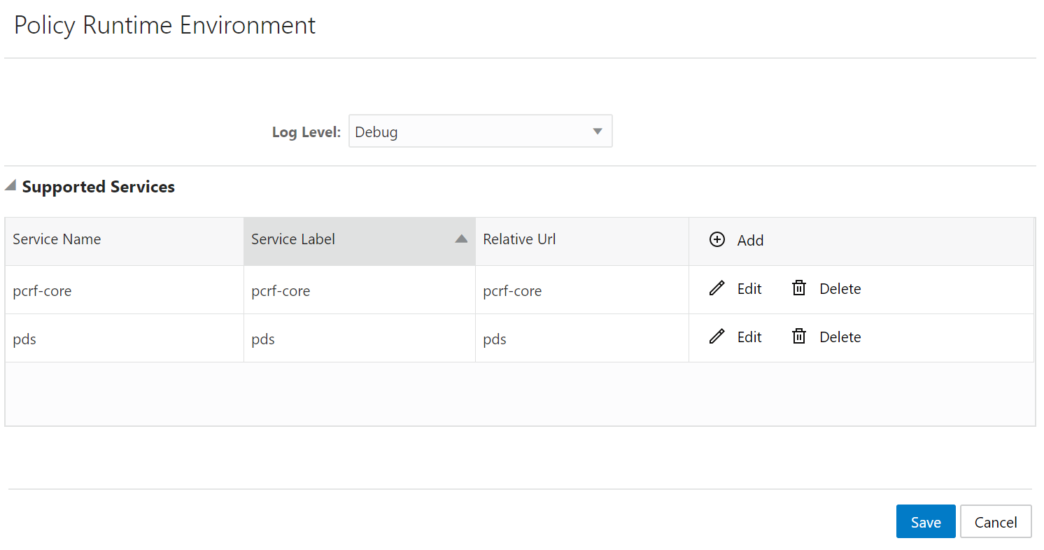 In the above example, pds service type is created.
Note:
The service name should be entered as pds. - Create Policy Project with pds Service Type. From the
navigation menu, under Policy
Management, click Policy
Projects. On Policy Projects page, click Create to create policy
project. While creating a policy project select pds as a service type.
The following screen capture shows the example of creating policy project with pds service type in GUI:
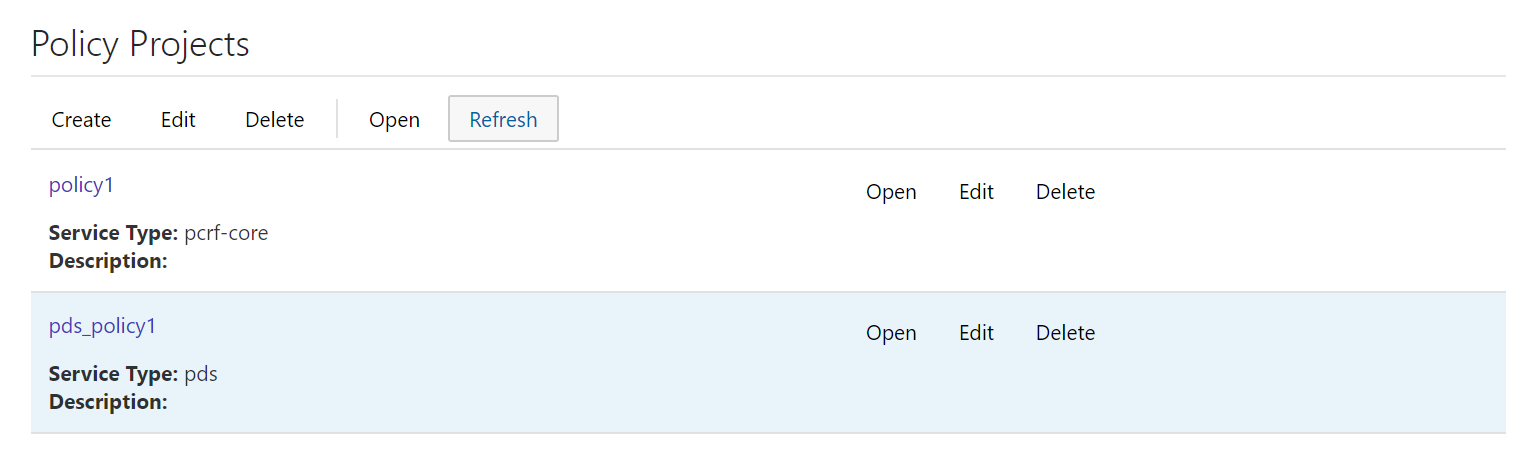 In the above example, s policy project is created with pds service
type.
In the above example, s policy project is created with pds service
type.
- Create policy action and condition in previously
created policy project. Click Open for the selected policy project and you
can see the project is a file. You can create the policy action and condition by
using the different blocks available under Conditions and Actions
under PDS.
The following screen capture shows the example of creating policy action and condition in GUI:

In the above example, if request received for configured IMSI ranges between 404050000000001 and 404050000000001, then PCF will forward request to PDS and PDS will forward the request to LDAP gateway to lookup user information in LDAP1.
Managing Subscriber Logging
Subscriber logging lets you to define a list of the subscribers (identifier) that you are interested to trace. This allows you to use this functionality to troubleshoot problematic subscribers in production without having to enable logs/traces for everyone. Using the subscriber logging, you can trace all the logs related to the subscribers for which the this functionality is enabled.
Note:
This functionality is only supported by Session Management (SM) service.Note:
The maximum number of subscribers that can be configured is 100.To configure a list of subscribers for logging:
- From the navigation menu, under Policy Common Configurations,
click Subscriber Logging.
The Subscriber Activity Logging screen screen appears with the listing of subscribers. You can create or import subscribers from this page.
Note:
Click Export to downlaod the available listing on your syatem. - Click Add to add the subscriber
item to the list..
The Create subscriber Activity Logging screen appears.
- From the Identifier Type drop-down, select the
subscriber identifier type. Supported subscriber identifier type are:
- GPSI
- SUPI
- IPV4
- IPV6
- Enter the subscriber identier value in the Identifier Value field for the selected identifier type.
- Select Enable to enable/disable the subscriber logging functionality for the selected subscriber.
- Click Save.
Note:
Use pencil icon or trash can icon available in the next column to update or delete the subscriber listing.- Subscriber Identification including associated IP Address information
- Type of Interface, Message type, Response code
- Policy related information (applied for the subscriber session)
- Date and Timestamps for all messages logged
Managing Custom Attributes
Note:
Custom schema yaml file should follow Open API standards.To import a custom schema file:
- Create a custom schema yaml file. Below is a sample yaml
file:
openapi: 3.0.0 info: description: Customer version: "0.0.1" title: Customer paths: /: get: operationId: get summary: get tags: - get responses: '200': description: OK content: application/json: schema: $ref: '#/components/schemas/Customer' components: schemas: Customer: type: object properties: phones: type: array items: type: string name: type: string address: $ref: '#/components/schemas/Address' Address: type: object properties: house: type: string street: type: string city: type: string - Save the yaml file on your system.
- From the navigation menu, under Policy Common Configurations,
click Custom Attributes.
The Custom Attributes Management screen appears with the listing of custom schema.
Note:
Click Export to downlaod the available listing on your syatem. - Click Import to import thr custom
schema yaml file.
The File Upload window opens.
- Click Drop Files here or click to upload. Locate the yaml file to be imported.
- Click Import. After the import is complete, the schemas are listed on the Custom Attributes Management page.
You can use this custom schema in creating policy conditions and actions by using blockly
interface under the Custom Attributes section in the Public section. Below
is a screen capture to describe how to access custom attributes blockly interface:
Managing Match Lists
In a wireless network, a match list is a set of defined values that can represent, for example, IDs or Internet addresses. Match lists provide whitelist and blacklist functions in policy rules. Match lists support wildcard matching.
A match list is a set of values in various categories, including access point names (APNs), subscriber IMSIs, location area codes (LACs), service area codes (SACs), Internet addresses, and user equipment identities. A match list can function as a whitelist (listing items to be included) or a blacklist (listing items to be excluded). By using a match list, you can, for example, apply a policy to all subscribers in a set of LACs, or block access to a list of Internet addresses known to be high risk. Match lists support wildcards. Using wildcards, a range of values can be specified compactly.
Creating a Match List
- From the navigation pane, under Policy Common
Configurations, select Match List.
The Match List Management page opens in the work area.
- Click
Create.
The Create Match List page opens.
- Enter the following
information:
- ID: The ID assigned to the match list.
- Name: The name
assigned to the match list.
The name can only contain the characters A-Z, a-z, 0-9, period (.), hyphen (-), and underline (_). The maximum length is 40 characters.
- Description: Free-form text
- Type: Select
from the following:
- string (default) - The list consists of strings.
- wildcard string - The list consists of wildcard match patterns that use an asterisk (*) to match zero or more characters or a question mark (?) to match exactly one character.
- Items:
- Click Save.
The match list is defined in the database and can now be used in a policy.
Modifying a Match List
- From the navigation pane, under Policy Common
Configurations, select Match List.
The Match List Management page opens in the work area, displaying the list of defined match lists.
- Select the match list you want to modify.
- Click
Edit.
The Edit Match List page opens.
- Modify match list information as required.
- Click
Save.
The match list is modified.
Deleting a Match List
- From the navigation pane, under Policy Common
Configurations, select Match List.
The Match List Management page opens in the work area, displaying the list of defined match lists.
- Select the match list you want to delete.
- Click
Delete.
A confirmation message displays.
- Click
OK.
The match list is deleted.
Importing the Match Lists
To import the match lists:
- Click
Import.
The File Upload window appears on the screen.
- Upload the files in required format by clicking Drop Files here or click to upload.
Exporting the Match Lists
You can export the match lists by clicking Export All. The Match Lists will be downloaded in a local machine.
Importing Configurable Objects
This section describes how to perform a bulk import of configurable objects into the system.
Importing Configuration Object Files
To import json or ZIP files:
- From the navigation pane, under Policy Common
Configurations, click Bulk Import.
The Upload option appears on the screen.
- Click
Upload.
Locate the file to be imported.
- Select a processing option
to use to
Handle collisions between imported items and existing items:
- Delete all before
importing The system deletes all objects for each object type matching the
import file before importing the object type json file.
Attention: This import strategy can result in object inconsistency. For example, if you import a ZIP file that only contains traffic profiles, all the traffic profiles are deleted first. However, if existing policies depend on the existing traffic profiles, and the import file does not contain them, the policies can become invalid.
- Overwrite with imported version For each object in the import file, if the object exists in the system, the import updates the object with the configuration contained in the import file. If an object does not exist, the system adds the object to the system.
- Delete all before
importing The system deletes all objects for each object type matching the
import file before importing the object type json file.
- Click Import.
The configuration objects and their configuration settings are imported into the database. After the import is complete, the window reports the results for each json file contained in the ZIP file.
Exporting Configurable Objects
This section describes how to perform a bulk export of configurable objects.
Exporting All Configuration Object Files
To export all configuration objects:
- From the navigation pane, under Policy Common
Configurations, click Bulk Export.
The Export All option appears on the screen.
- Click
Export All
.
A ZIP file is downloaded to your local computer.