3 BSF Features
This section describes the key features of Oracle Communications Cloud Native Core, Binding Support Function (BSF).
3.1 Support for SBI Message Priority Header
BSF supports 3gpp-Sbi-Message-Priority header in order to
enable overload and congestion control through informed throttling decisions.
Using 3gpp-Sbi-Message-Priority header, BSF and the associated producers, consumers and proxies such as SCP, NRF, and PCF can distinguish between high-priority and low-priority Service-Based Interface (SBI) messages.
The 3gpp-Sbi-Message-Priority header specifies HTTP/2 message priority
values ranging from 0 (highest) to 31 (lowest). Integrating this header enables
priority-based processing of both ingress and egress HTTP/2 SBI messages.
BSF as a consumer: BSF sends the
3gpp-Sbi-Message-Priority header in outgoing HTTP requests and also
supports receiving it in responses in all the interaction between BSF and NRF, consuming
NRF Management services and BSF interaction with PCF for stale session notification
confirmations.
BSF as a producer: BSF receives the
3gpp-Sbi-Message-Priority header in the incoming HTTP requests and
propagates the appropriate header value in responses in BSF interaction with PCF for
Nbsf services such as Register, Deregister, and Discovery.
Note:
The 3gpp-Sbi-Message-Priority header should be integrated before
configuring congestion control mechanism.
Call Flow
Figure 3-1 Sample call flow for session binding registration with BSF as a producer
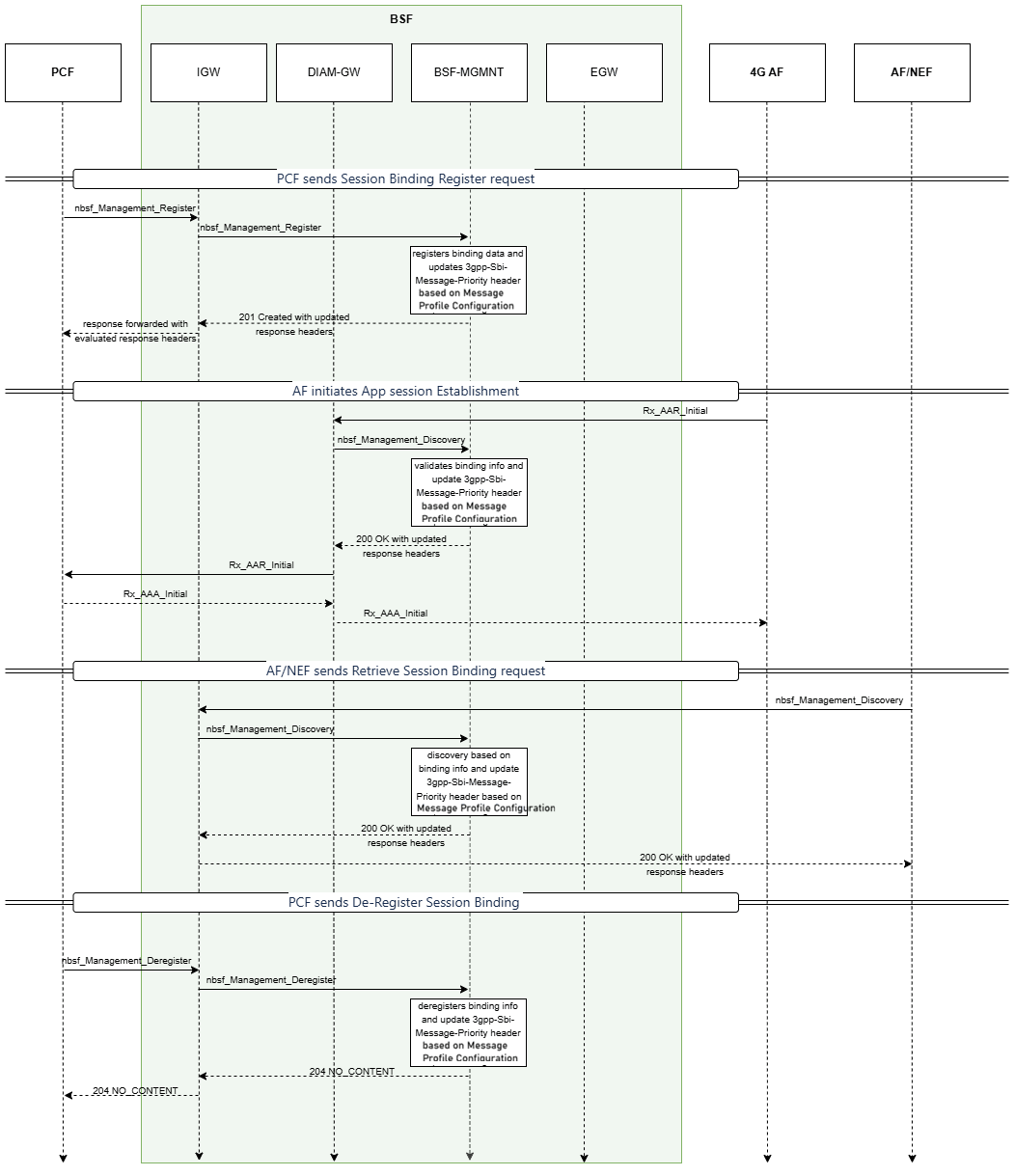
- PCF Sends Session Binding Register Request
- The Policy Control Function (PCF) sends a Session Binding
Register request to the BSF (Binding-Support-Function) through the
nbsf_Management_Registerinterface. BSF receives the request through Ingress Gateway. - BSF Management service records the binding data and updates the
3gpp-Sbi-Message-Priorityheader based on configuration. - BSF responds to PCF with
201 Createdmessage, indicating successful registration, along with updated3gpp-Sbi-Message-Priorityheaders.
- The Policy Control Function (PCF) sends a Session Binding
Register request to the BSF (Binding-Support-Function) through the
- AF Initiates App Session Establishment
- The AF initiates application session establishment by sending an Rx AAR-I request to the BSF Diameter Gateway.
- The BSF Diameter Gateway performs binding discovery by sending a request to the BSF Management service. The BSF Management service validates the binding information and returns a 200 OK response with the selected PCF binding information to the BSF Diameter Gateway.
- During this internal SBI/HTTP interaction, BSF Management service evaluates the 3gpp-Sbi-Message-Priority header based on the selected Message Priority Profile. Based on the profile configuration, the response may include the evaluated 3gpp-Sbi-Message-Priority header.
- BSF Diameter Gateway forwards the Rx AAR-I request to the selected PCF and returns the Rx AAA-I response from PCF to the AF.
- AF/NEF Sends Retrieve Session Binding Request
- Application Function(AF)/Network Exposure Function (NEF) sends a
Retrieve Session Binding request using the
nbsf_Management_Discoveryinterface to BSF. - The BSF performs discovery based on the current binding information, updates the priority header appropriately.
- BSF responds to AF/NEF with
200 OKalong with the updated 3gpp-Sbi-Message-Priority headers.
- Application Function(AF)/Network Exposure Function (NEF) sends a
Retrieve Session Binding request using the
- PCF Sends De-register Session Binding
- The PCF sends a Deregister request using the
nbsf_Management_Deregisterinterface to BSF. - BSF Management service processes the deregistration by removing the binding information, and updates the priority header accordingly.
- BSF confirms de-registration by returning
204 NO
                                CONTENT
, acknowledging successful deletion of the session binding.BSF includes 3gpp-Sbi-Message-Priority header in the response to deregister request based on the configuration.
- The PCF sends a Deregister request using the
Figure 3-2 Sample call flow for session binding registration with BSF as a consumer
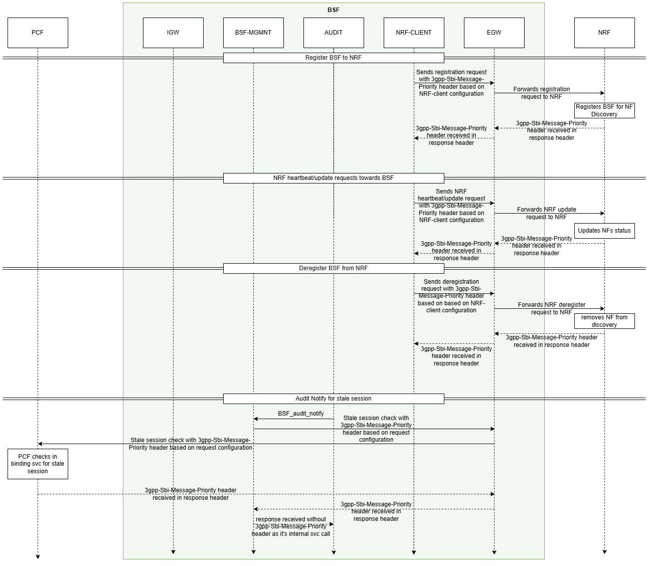
- BSF Registration with NRF
- BSF sends a registration request to NRF with
3gpp-Sbi-Message-Priorityheader in the request. The request is sent through NRF Client and Egress Gateway. - NRF processes the registration request and responds with
3gpp-Sbi-Message-Priorityheader in its response.
- BSF sends a registration request to NRF with
- BSF receives Heartbeat/Update Requests from NRF
- BSF sends heartbeat or status update requests to the NRF to confirm and
update its status in the network.
The request containing
3gpp-Sbi-Message-Priorityheader is sent to NRF through NRF Client. - NRF processes the request, updates the status of BSF, and responds to
BSF with
3gpp-Sbi-Message-Priorityheader in the response.
- BSF sends heartbeat or status update requests to the NRF to confirm and
update its status in the network.
- BSF Deregistration from NRF
- BSF sends a deregistration request to NRF. The deregistration request
containing
3gpp-Sbi-Message-Priorityheader is sent to NRF through NRF Client and Egress Gateway. - NRF processes the deregistration request and responds to BSF with
3gpp-Sbi-Message-Priorityheader in its response.
- BSF sends a deregistration request to NRF. The deregistration request
containing
- Audit Notify for Stale Session
- The Audit service for BSF sends an audit notification (BSF_audit_Notify) to BSF Management service.
- BSF sends a stale session check request to PCF. The request containing
3gpp-Sbi-Message-Priorityheader is sent to PCF through Egress Gateway. - The PCF processes the request, checks for any stale session, and
responds to BSF. The response from PCF contains the
3gpp-Sbi-Message-Priorityheader. - BSF Management service sends the response from PCF to Audit service
without
3gpp-Sbi-Message-Priorityheader.
Upgrade Impact
While upgrading BSF from 25.2.1xx release to 25.2.2xx release or later
versions, the default priority for AutonomousNfPatch and
AutonomousNfDeRegistration should be 3 and 2 respectively. The
default priority of all other message types must be 1.
Managing Support for SBI Message Priority Header
This feature is not enabled by default. The feature gets
enabled when a message priority profile is selected for Message
Priority Profile field on Management
Service page on CNC Console, and
3gpp-Sbi-Message-Priority header is added to the outgoing
and incoming HTTP requests and responses to BSF depending on the configuration
of the Message Priority Profile selected for BSF Management
Service.
Support for SBI message priority header can be configured either using CNC console or using REST API.
- Configure the Message Profile as explained in Message Profiles.
- Select the required message priority profile to be used under Message Priority Profile section on Management Service page as explained in Management Service.
- Configure the traffic prioritization as explained in NRF Agent Service.
Configure using REST API
-
Get Message ProfileAPI for BSF Management service is used to get the configuration of a particular message profile.Request URL:
{apiRoot}/oc-bsf-configuration/v1/services/common/messageProfiles/{messageProfileName} -
Create Message ProfileAPI for BSF Management service is used to create the configuration of a particular message profile.Request URL:
{apiRoot}/oc-bsf-configuration/v1/services/common/messageProfiles -
Update Message ProfileAPI for BSF Management service is used to update the configuration of a particular message profile.Request URL:
{apiRoot}/oc-bsf-configuration/v1/services/common/messageProfiles/{messageProfileName} -
Delete Message ProfileAPI for BSF Management service is used to delete the configuration of a particular message profile.Request URL:
{apiRoot}/oc-bsf-configuration/v1/services/common/messageProfiles/{messageProfileName} -
Export Message ProfileAPI for BSF Management service is used to export the configuration of a particular message profile.Request URL:
{apiRoot}/oc-bsf-configuration/v1/services/common/messageProfiles/export -
Import Message ProfileAPI for BSF Management service is used to import the configuration of a particular message profile.Request URL:
{apiRoot}/oc-bsf-configuration/v1/services/common/messageProfiles/import
-
Get NRF Agent Service configurationsAPI to get the configuration of traffic prioritization feature of NRF Agent service.Request URL:
{apiRoot}/oc-bsf-configuration/v1/services/nrfAgentServiceConfig -
Update NRF Agent Service configurationsAPI to update the configuration of traffic prioritization feature of NRF Agent service.Request URL:
{apiRoot}/oc-bsf-configuration/v1/services/nrfAgentServiceConfig -
Export NRF Agent Service configurationsAPI to export the configuration of traffic prioritization feature of NRF Agent service.Request URL:
{apiRoot}/oc-bsf-configuration/v1/services/nrfAgentServiceConfig/export -
Import NRF Agent Service configurationsAPI to import the configuration of traffic prioritization feature of NRF Agent service.Request URL:
{apiRoot}/oc-bsf-configuration/v1/services/nrfAgentServiceConfig/import
For more information, see Management Service section in Oracle Communications Cloud Native Core, Binding Support Function REST Specification Guide
Observability
Metrics
The following metrics are used to get the statistics on the total number of requests received and requests sent by BSF, total number of responses sent by BSF and responses received by BSF during register, deregister, discovery, and stale session scenarios:
- ocbsf_http_message_priority_request_count_total
- ocbsf_http_message_priority_response_count_total
For more information, see BSF Management Service.
Logging
The following logs are generated when 3gpp-Sbi-Message-Priority
header is enabled.
Server filter logging
{"instant":{"epochSecond":1758784050,"nanoOfSecond":383374000},"thread":"default-nioEventLoopGroup-1-5","level":"INFO","loggerName":"ocpm.bsf.api.management.messageprofile.PriorityHeaderInboundRequestFilter","message":"incoming request priority headers: {3gpp-sbi-message-priority=[8], oc-message-priority=[9], Content-Type=[application/json; charset=UTF-8], Content-Length=[1520], Host=[localhost:8080], Connection=[Keep-Alive], User-Agent=[Apache-HttpClient/4.5.13 (Java/17.0.12)], Accept-Encoding=[gzip,deflate]}","endOfBatch":false,"loggerFqcn":"org.apache.logging.slf4j.Log4jLogger","threadId":66,"threadPriority":5,"messageTimestamp":"2025-09-25T12:37:30.383+0530","ocLogId":"${ctx:ocLogId}"}
{"instant":{"epochSecond":1758784050,"nanoOfSecond":383578000},"thread":"default-nioEventLoopGroup-1-5","level":"DEBUG","loggerName":"ocpm.bsf.api.management.messageprofile.PriorityHeaderInboundRequestFilter","message":"buildParams map generated from request with values: {interfaceType=Nbsf_Management, messageType=Register, 3gpp-sbi-message-priority=8, oc-message-priority=9}","endOfBatch":false,"loggerFqcn":"org.apache.logging.slf4j.Log4jLogger","threadId":66,"threadPriority":5,"messageTimestamp":"2025-09-25T12:37:30.383+0530","ocLogId":"${ctx:ocLogId}"}
{"instant":{"epochSecond":1758784050,"nanoOfSecond":383650000},"thread":"default-nioEventLoopGroup-1-5","level":"DEBUG","loggerName":"ocpm.pcf.framework.ruleengine.messageprofile.MessageProfileRuleEngine","message":"select message profile rule with attribute map {interfaceType=Nbsf_Management, messageType=Register, 3gpp-sbi-message-priority=8, oc-message-priority=9}","endOfBatch":false,"loggerFqcn":"org.apache.logging.slf4j.Log4jLogger","threadId":66,"threadPriority":5,"messageTimestamp":"2025-09-25T12:37:30.383+0530","ocLogId":"${ctx:ocLogId}"}
{"instant":{"epochSecond":1758784050,"nanoOfSecond":383840000},"thread":"default-nioEventLoopGroup-1-5","level":"DEBUG","loggerName":"ocpm.pcf.framework.ruleengine.messageprofile.MessageProfileRuleEngine","message":"Matched messageProfileRule messageId=HIGH_PRIORITY_ANY_I","endOfBatch":false,"loggerFqcn":"org.apache.logging.slf4j.Log4jLogger","threadId":66,"threadPriority":5,"messageTimestamp":"2025-09-25T12:37:30.383+0530","ocLogId":"${ctx:ocLogId}"}
{"instant":{"epochSecond":1758784050,"nanoOfSecond":383901000},"thread":"default-nioEventLoopGroup-1-5","level":"DEBUG","loggerName":"ocpm.bsf.api.management.messageprofile.PriorityHeaderInboundRequestFilter","message":"incoming server request contains oc-message-priority value as : 9","endOfBatch":false,"loggerFqcn":"org.apache.logging.slf4j.Log4jLogger","threadId":66,"threadPriority":5,"messageTimestamp":"2025-09-25T12:37:30.383+0530","ocLogId":"${ctx:ocLogId}"}
{"instant":{"epochSecond":1758784050,"nanoOfSecond":384550000},"thread":"default-nioEventLoopGroup-1-5","level":"DEBUG","loggerName":"ocpm.bsf.api.management.messageprofile.PriorityHeaderInboundRequestFilter","message":"incoming server request evaluated 3gpp-sbi-message-priority value is : 3 for Message Profile : MessageProfileRule(messageID=HIGH_PRIORITY_ANY_I, rulePriority=5, interfaceType=Nbsf_Management, messageType=Any, requestPriorityValue=3, requestPriorityOverride=Always, responsePriorityAssign=Never, responsePriorityValue=0, messageProfileFilterConditions=null)","endOfBatch":false,"loggerFqcn":"org.apache.logging.slf4j.Log4jLogger","threadId":66,"threadPriority":5,"messageTimestamp":"2025-09-25T12:37:30.384+0530","ocLogId":"${ctx:ocLogId}"}
{"instant":{"epochSecond":1758784050,"nanoOfSecond":384685000},"thread":"default-nioEventLoopGroup-1-5","level":"INFO","loggerName":"ocpm.bsf.api.management.messageprofile.PriorityHeaderInboundRequestFilter","message":"final incoming request priority headers: {oc-message-priority=[8], Content-Type=[application/json; charset=UTF-8], Content-Length=[1520], Host=[localhost:8080], Connection=[Keep-Alive], User-Agent=[Apache-HttpClient/4.5.13 (Java/17.0.12)], Accept-Encoding=[gzip,deflate], oc-message-priority=[3]}","endOfBatch":false,"loggerFqcn":"org.apache.logging.slf4j.Log4jLogger","threadId":66,"threadPriority":5,"messageTimestamp":"2025-09-25T12:37:30.384+0530","ocLogId":"${ctx:ocLogId}"}
{"instant":{"epochSecond":1758784050,"nanoOfSecond":384916000},"thread":"default-nioEventLoopGroup-1-5","level":"DEBUG","loggerName":"ocpm.bsf.api.management.metrics.BsfMetrics","message":"Pegging ocbsf_http_message_priority_request_count_total with direction : in, rcvd_priority: 9, eval_priority: 3, interfaceType: Nbsf_Management, msgType: Register","endOfBatch":false,"loggerFqcn":"org.apache.logging.slf4j.Log4jLogger","threadId":66,"threadPriority":5,"messageTimestamp":"2025-09-25T12:37:30.384+0530","ocLogId":"${ctx:ocLogId}"}
{"instant":{"epochSecond":1758784050,"nanoOfSecond":863867000},"thread":"boundedElastic-1","level":"DEBUG","loggerName":"ocpm.bsf.api.management.metrics.BsfMetrics","message":"Pegging the Ingress Response Metric for Operation Type : register, Response Code CREATED","endOfBatch":false,"loggerFqcn":"org.apache.logging.slf4j.Log4jLogger","threadId":68,"threadPriority":5,"messageTimestamp":"2025-09-25T12:37:30.863+0530","ocLogId":"${ctx:ocLogId}"}
{"instant":{"epochSecond":1758784050,"nanoOfSecond":864543000},"thread":"boundedElastic-1","level":"INFO","loggerName":"ocpm.bsf.api.management.messageprofile.PriorityHeaderInboundRequestFilter","message":"outgoing server response priority headers: {Location=[/nbsf-management/v1/pcfBindings/91795ebd-74f3-4c90-9bfd-76f22a72a5b3], Content-Type=[application/json], date=[Thu, 25 Sep 2025 07:07:30 GMT], Access-Control-Allow-Origin=[*, *], Access-Control-Allow-Methods=[GET, POST, DELETE, PUT, GET, POST, DELETE, PUT], Access-Control-Allow-Headers=[Content-Type, Content-Type]}, for request headers: {3gpp-sbi-message-priority=[8], Content-Type=[application/json; charset=UTF-8], Content-Length=[1520], Host=[localhost:8080], Connection=[Keep-Alive], User-Agent=[Apache-HttpClient/4.5.13 (Java/17.0.12)], Accept-Encoding=[gzip,deflate], oc-message-priority=[3]}","endOfBatch":false,"loggerFqcn":"org.apache.logging.slf4j.Log4jLogger","threadId":68,"threadPriority":5,"messageTimestamp":"2025-09-25T12:37:30.864+0530","ocLogId":"${ctx:ocLogId}"}
{"instant":{"epochSecond":1758784050,"nanoOfSecond":864665000},"thread":"boundedElastic-1","level":"DEBUG","loggerName":"ocpm.bsf.api.management.messageprofile.PriorityHeaderInboundRequestFilter","message":"No matching message profile is found, ignoring outgoing server response header processing for 3gpp-sbi-message-priority priority header","endOfBatch":false,"loggerFqcn":"org.apache.logging.slf4j.Log4jLogger","threadId":68,"threadPriority":5,"messageTimestamp":"2025-09-25T12:37:30.864+0530","ocLogId":"${ctx:ocLogId}"}
{"instant":{"epochSecond":1758784050,"nanoOfSecond":864712000},"thread":"boundedElastic-1","level":"DEBUG","loggerName":"ocpm.bsf.api.management.metrics.BsfMetrics","message":"Pegging ocbsf_http_message_priority_response_count_total with direction : out, rcvd_priority: NA, eval_priority: NA, interfaceType: Nbsf_Management, msgType: Register, responseCode: 201","endOfBatch":false,"loggerFqcn":"org.apache.logging.slf4j.Log4jLogger","threadId":68,"threadPriority":5,"messageTimestamp":"2025-09-25T12:37:30.864+0530","ocLogId":"${ctx:ocLogId}"}
Client filter logging
{"instant":{"epochSecond":1758783713,"nanoOfSecond":823759000},"thread":"Thread-0","level":"INFO","loggerName":"ocpm.bsf.api.management.service.BsfConfigServiceImpl","message":"configurationChanged attempt, topic: common.bsf.messageProfiles, item: class ConfigurationItem { key: Audit_Contract_1, value: {\"messageProfileName\":\"bsf-mpp-audit1\",\"serviceType\":\"BSF_Management\",\"messageProfileAttributes\":[{\"messageID\":\"DEFAULT_AUDIT_ALWAYS\",\"rulePriority\":1,\"interfaceType\":\"Npcf_Binding_Audit\",\"messageType\":\"Audit_Notify\",\"messageProfileFilterConditions\":[],\"requestPriorityOverride\":\"Always\",\"requestPriorityValue\":10,\"responsePriorityAssign\":\"Never\"},{\"messageID\":\"DEFAULT_AUDIT_IF_NOT_PRESENT\",\"rulePriority\":2,\"interfaceType\":\"Npcf_Binding_Audit\",\"messageType\":\"Audit_Notify\",\"messageProfileFilterConditions\":[],\"requestPriorityOverride\":\"IfNotPresent\",\"requestPriorityValue\":11,\"responsePriorityAssign\":\"Never\"},{\"messageID\":\"DEFAULT_AUDIT_NEVER\",\"rulePriority\":3,\"interfaceType\":\"Npcf_Binding_Audit\",\"messageType\":\"Audit_Notify\",\"messageProfileFilterConditions\":[],\"requestPriorityOverride\":\"Never\",\"responsePriorityAssign\":\"Never\"}]}, version: 0, topicInfo: class TopicInfo { id: 77, name: common.bsf.messageProfiles, description: Created by config server., modifydate: null, version: 89 }, labels: null }","endOfBatch":false,"loggerFqcn":"org.apache.logging.slf4j.Log4jLogger","threadId":28,"threadPriority":5,"messageTimestamp":"2025-09-25T12:31:53.823+0530","ocLogId":"${ctx:ocLogId}"}
{"instant":{"epochSecond":1758783713,"nanoOfSecond":824031000},"thread":"Thread-0","level":"INFO","loggerName":"ocpm.bsf.api.management.service.BsfConfigServiceImpl","message":"MessageProfiles list updated for : bsf-mpp-audit1","endOfBatch":false,"loggerFqcn":"org.apache.logging.slf4j.Log4jLogger","threadId":28,"threadPriority":5,"messageTimestamp":"2025-09-25T12:31:53.824+0530","ocLogId":"${ctx:ocLogId}"}
{"instant":{"epochSecond":1758783727,"nanoOfSecond":848469000},"thread":"Thread-0","level":"INFO","loggerName":"ocpm.cne.common.configclient.ConfigurationAgent","message":"Configuration changed. Topic:[bsf.managementservice], Key:[bsf.managementservice], Value:[{\"audit\":{\"enable\":true,\"notificationRate\":\"100\",\"ttl\":\"55\",\"maxTtl\":\"155\",\"frequency\":\"10\",\"queryToPcf\":true,\"vendorId\":\"vendor1\"},\"messagePriority\":{\"messagePriorityProfile\":\"bsf-mpp-audit1\"}}], version:1,","endOfBatch":false,"loggerFqcn":"org.apache.logging.slf4j.Log4jLogger","threadId":28,"threadPriority":5,"messageTimestamp":"2025-09-25T12:32:07.848+0530","ocLogId":"${ctx:ocLogId}"}
{"instant":{"epochSecond":1758783724,"nanoOfSecond":148161000},"thread":"BSFManagementService_ThreadPool_1","level":"INFO","loggerName":"ocpm.bsf.api.management.messageprofile.PriorityHeaderClientFilter","message":"outgoing request priority headers: {Accept=[application/problem+json, application/json], Content-Type=[application/json], 3gpp-sbi-target-apiroot=[http://dummyURL]}","endOfBatch":false,"loggerFqcn":"org.apache.logging.slf4j.Log4jLogger","threadId":70,"threadPriority":5,"messageTimestamp":"2025-09-25T12:32:04.148+0530","ocLogId":"${ctx:ocLogId}"}
{"instant":{"epochSecond":1758783724,"nanoOfSecond":149078000},"thread":"BSFManagementService_ThreadPool_1","level":"INFO","loggerName":"ocpm.bsf.api.management.messageprofile.PriorityHeaderClientFilter","message":"final outgoing request priority headers: {Accept=[application/problem+json, application/json], Content-Type=[application/json], 3gpp-sbi-target-apiroot=[http://dummyURL], 3gpp-sbi-message-priority=[10]}","endOfBatch":false,"loggerFqcn":"org.apache.logging.slf4j.Log4jLogger","threadId":70,"threadPriority":5,"messageTimestamp":"2025-09-25T12:32:04.149+0530","ocLogId":"${ctx:ocLogId}"}
{"instant":{"epochSecond":1758783724,"nanoOfSecond":225723000},"thread":"HttpLoggingJettyHttpClient@6ef0bb37-75","level":"INFO","loggerName":"ocpm.bsf.api.management.service.AuditServiceHelperImpl","message":"Response code OK and header {3gpp-sbi-message-priority=[8], Connection=[keep-alive], Content-Length=[0]} received from PCF for notification request for id 7aea9548-4a38-4381-8934-49abf08bda38 from URI: http://dummyURL/staleSessionVerificationPath","endOfBatch":false,"loggerFqcn":"org.apache.logging.slf4j.Log4jLogger","threadId":75,"threadPriority":5,"messageTimestamp":"2025-09-25T12:32:04.225+0530","ocLogId":"${ctx:ocLogId}"}
{"instant":{"epochSecond":1758783724,"nanoOfSecond":226155000},"thread":"HttpLoggingJettyHttpClient@6ef0bb37-75","level":"INFO","loggerName":"ocpm.bsf.api.management.messageprofile.PriorityHeaderClientFilter","message":"incoming client response priority headers: {3gpp-sbi-message-priority=[8], Connection=[keep-alive], Content-Length=[0]}","endOfBatch":false,"loggerFqcn":"org.apache.logging.slf4j.Log4jLogger","threadId":75,"threadPriority":5,"messageTimestamp":"2025-09-25T12:32:04.226+0530","ocLogId":"${ctx:ocLogId}"}
3.2 Application Framework Change
BSF supports Micronaut from 25.2.200 onwards.
- Updated name of the following Diameter Gateway Metrics:
Table 3-1 Updates in Diameter Gateway Metrics
Old Metric Name New Metric Name ocbsf_diam_pending_requests_total ocbsf_diam_pending_requests ocbsf_diam_service_overall_processing_time_seconds ocbsf_diam_service_overall_processing_time_seconds_bucket - Updated name of the following BSF Management Metrics:
Table 3-2 Updates in BSF Management Metrics
Old Metric Name New Metric Name spring_data_repository_invocations_seconds_sum data_repository_invocations_seconds_sum spring_data_repository_invocations_seconds_count data_repository_invocations_seconds_count spring_data_repository_invocations_seconds_max data_repository_invocations_seconds_max - Removed the following metrics:
- ocbsf_diam_response_latency_seconds
- ocbsf_diam_service_overall_processing_time_seconds
Note:
This metric,ocbsf_diam_service_overall_processing_time_seconds, is removed. In order to get quantile data, use Prometheus Histogram (which contains bucket). You can use histogram_percentile from PQL to get much more accurate data from the bucket as per the use cases. Use this metric,ocbsf_diam_service_overall_processing_time_seconds_bucketto fetch the quantile data. - Removed the global.isIpvSixSetup parameter.
3.3 Support for Optimizing N7 Session Lookup for AAR messages in Rx Call Flows
BSF supports optimize the N7 session lookup for AAR-I messages in Rx call flows. BSF stores the cookie received in the binding registration request from Policy.
Whenever BSF receives a AAR-I from an AF, it searches for the PCF identity
of the Rx session and the cookie stored in the database. If the details are present, BSF
Management service sends the details as a header in the request to Diameter Gateway. The
Diameter Gateway uses the details in the header to prepare
ocnf-service-cookie Custom AVP. Diameter Gateway sends the
ocnf-service-cookie Custom AVP in the AAR-I request to Policy.
These details enable Policy to identify the session owner and the session identifier to
further process the AAR-I request.
Data propagation from Policy and storage in BSF Management Service
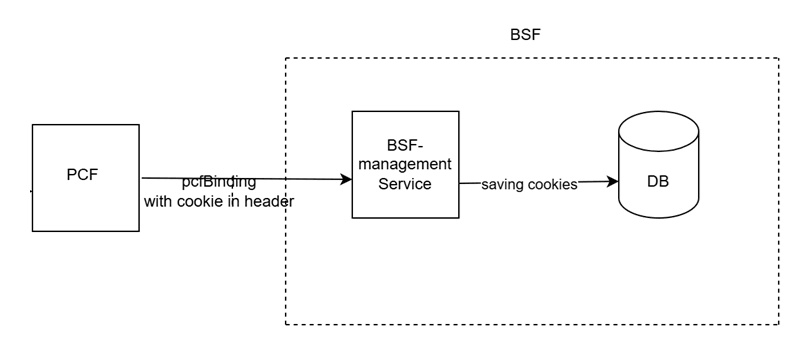
During binding registration request, BSF receives the N7 session identifier details as a ocnf-service-cookie in the header of the HTTP request from Policy. The ocnf-service-cookie header includes session owner and session identifier such as SMPolicyAssociationID details.
If ENABLE_PCF_COOKIE Advanced Settings key in BSF Management Service is
enabled, BSF stores the cookie data in ocpm_bsf.pcf_binding table in
BSF Management Service database.
Figure 3-3 ocnf-service-cookie received by BSF from Policy
ocnf-service-cookie header that BSF receives from
Policy is as
follows:ocnf-service-cookie:{
"cookieOwner": "PCF-SM",
"cookieData": {
"SmPolicyAssociationId": "xxx"
}
}Data lookup in BSF Management Service
Whenever BSF receives a AAR-I request from an AF, if ENABLE_PCF_COOKIE
Advanced Settings key in BSF Management Service is enabled, the Diameter Gateway
performs initial lookup of the PCF identity by querying BSF-Management Service
database.
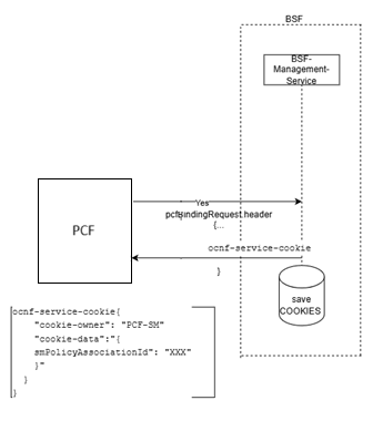
If the Rx session details are already stored in the ocpm_bsf.pcf_binding
table in Management Service database, Diameter Gateway retrieves the details, encodes
the details, and adds them to a custom AVP called OCNF-SERVICE-COOKIE.
BSF includes this OCNF-SERVICE-COOKIE AVP in the AAR-I message and
sends the message to Policy.
Figure 3-4 OCNF-SERVICE-COOKIE sent by BSF to Policy
Policy extracts the details in OCNF-SERVICE-COOKIE AVP and uses it to
identify the session owner and session identifier in order to further process the AAR-I
message.
For more details on how Policy processes the cookie details, see Optimizing N7 Session Lookup for AAR messages in Rx Callflows section in Oracle Communications Cloud Native Core, Converged Policy User Guide.
Upgrade Impact
For this feature to work, make sure that both BSF and Policy are upgraded to 25.2.100 or later versions.
Managing Support for Optimizing N7 Session Lookup for AAR messages in Rx Call Flows
Enable and Configure
ENABLE_PCF_COOKIE Advanced Settings key in Management Service page
on CNC Console is used to enable support for optimizing N7 session lookup for AAR
messages in Rx call flows. For more information, see Management Service.
Observability
Metrics
ocbsf_pcf_cookie_totalocbsf_ocnf_service_cookie_total
For more information, see BSF Management Service.
3.4 BSF Management Service Pod Congestion Control
BSF Management service interacts with other services such as PCF-Binding, Audit, Diameter Gateway services and also with the database. At times, excessive traffic from consumer services toward BSF Management service can be observed in the network, which can result in high CPU utilization and high memory utilization. The service gets congested and can cause performance degradation in its service response time and eventually reach a state of service unavailability. To handle this, the service implements congestion control mechanism and ensures that its service is protected from congestion and, also its service is consistently available to the consumer services.
Figure 3-5 BSF Management Service interactions with other Services
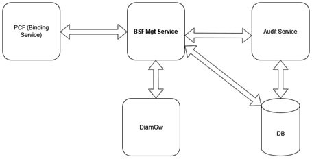
The Pod Congestion Control feature in BSF application is a crucial mechanism to ensure consistent service availability and performance, especially in scenarios with high traffic and resource utilization. It is designed to identify congestion conditions and apply load shedding rules to maintain optimal service levels.
- Determining Pod Congestion State
- Triggering Pod Congestion Control
Determining Pod Congestion State
- NORMAL
- DANGER_OF_CONGESTION (DOC)
- CONGESTION_L1
- CONGESTION_L2
- CONGESTED
- CPU: The CPU usage for congestion state is calculated by comparing the CPU usage of the container (monitored using cgroup parameter, cpuacct.usage, which provides current cpu usage in nanoseconds) with the configured threshold.
- Queue: For the DOC, CONGESTION_L1, CONGESTION_L2, and CONGESTED pod states, compare the number of pending messages in the queue with the configured pending messages threshold.
stateChangeSampleCount: This REST API parameter can be configured to specify after how many continuous intervals, the pod state can be changed. This value can range from 1 to 2147483647.stateCalculationInterval: This REST API parameter can be configured to specify the time duration or interval, after which the pod congestion state will be re-verified. This interval is configured in milliseconds and can range from 50 to 2147483647.
Table 3-3 BSF Management Service Congestion States
| Congestion States | CPU (%) | Queue Count (Pending Requests) |
|---|---|---|
| DANGER_OF_CONGESTION (DOC | 75 | 175 |
| CONGESTION_L1 | 80 | 200 |
| CONGESTION_L2 | 85 | 225 |
| CONGESTED | 90 | 250 |
For more information about congestion control threshold profiles, see section in CNC Console.
Triggering Pod Congestion Control
With Congestion Control feature enabled for BSF Management service,
every time a message is fetched for processing, the system checks the
current congestion state of the pod. If the current state is either in
DOC, CONGESTION_L1,
CONGESTION_L2, or Congested state,
then the congestion control mechanism is triggered. After verifying that the
message type is a request, a request priority is assigned to it. If the
request priority is greater than or equal to the discard priority, then the
message is rejected, otherwise it is accepted.
Congestion Control Load Shedding using Discard and Request Priority
Table 3-4 BSF Management Service Default Discard Priorities:
| Congestion State | Discard Priority (Default Value) |
|---|---|
| DANGER_OF_CONGESTION | 30 |
| CONGESTION_L1 | 24 |
| CONGESTION_L2 | 18 |
| CONGESTED | 14 |
You can add the following keys to configure the message priority for different rest endpoints for BSF Management Service using CNC Console at BSF → Service Configurations → Management Service → Advanced Settings section. The message priority value ranges between 0 to 31, with 0 being the highest, and 31 being the lowest priority. If an invalid value is provided, then the default priority shall be considered.
Table 3-5 BSF Management Service Request Default Priorities
| Message Type | Advanced Settings Key | Default Priority |
|---|---|---|
| Get Pcf Bindings | BSF_MGMT_GET_PCF_BINDING_REQUEST_PRIORITY | 15 |
| Post Pcf Bindings | BSF_MGMT_POST_PCF_BINDING_REQUEST_PRIORITY | 20 |
| Delete Pcf Bindings | BSF_MGMT_DELETE_PCF_BINDING_REQUEST_PRIORITY | 16 |
| Post Audit Notification | BSF_MGMT_POST_AUDIT_NOTIFY_REQUEST_PRIORITY | 25 |
| Delete Audit Notification | BSF_MGMT_DELETE_AUDIT_NOTIFY_REQUEST_PRIORITY | 25 |
| Get Session Viewer Pcf Bindings | BSF_MGMT_GET_SESSION_VIEWER_PCF_BINDING_REQUEST_PRIORITY | 28 |
| Post Session Viewer Pcf Bindings Cleanup | BSF_MGMT_POST_SESSION_VIEWER_DELETE_PCF_BINDING_REQUEST_PRIORITY | 18 |
| Delete Session Viewer Pcf Bindings Cleanup All | BSF_MGMT_DELETE_SESSION_VIEWER_DELETEALL_PCF_BINDING_REQUEST_PRIORITY | 18 |
- For requests coming from Diameter Gateway, the requests priority number is retrieved from oc-message-priority parameter in the http request header. But if this request header parameter is not present or its value is not set, then the message priority shall be based on the configured values from Advanced Settings or Default priority values.
- For requests coming from Ingress Gateway, the priority is based on 3gpp-sbi-message-priority parameter in http request header. But if this request header parameter is not present or its value is not set, then the priority shall be based on configured values from Advanced Settings or on the default priority values.
- The request priority value ranges between 0 to 31, with 0 being the highest, and 31 being the lowest priority. If an invalid value is provided, then the default priority shall be considered.
Thus the precedence order for assigning message priority shall be
from oc-message-priority →
3gpp-sbi-message-priority → Advanced
Settings Priority → Default Priority.
You can also configure the result codes for the rejected requests when configuring the load rules. By default, BSF Management service sends 503 as response code with error cause as 'NF_CONGESTION'. You can configure the response code and cause using CNC Console SBI Error Codes configuration in General Settings. The response code configured should be 4xx or 5xx error status only.
{
  "errorDetails":{
  "status":"503",
  "cause":"NF_CONGESTION",
  "message":"Pod <pod-name> is in CONGESTION_L1",
  "targetService":"BSF_MGMT"
  }
}
BSF Management service Pod Congestion Control
Enable
By default, the Pod Congestion Control is disabled for BSF Management service. You can enable this feature using CNC Console or REST API for Policy.
Configure Using CNC Console
To enable the feature using CNC Console, set the Enable parameter in Settings page under Congestion Control for Overload and Congestion Control Configurations.
To configure UE service pod congestion control feature in CNC Console, see section.
Configure Using REST API
Perform the feature configurations as described in "Congestion Control" section in Oracle Communications Cloud Native Core, Binding Support Function REST Specification Guide.
Observability
Metrics:
pod_congestion_statepod_resource_stresspod_resource_congestion_statepod_cong_state_report_totalpod_resource_congestion_state_report_totalcongestion_http_pending_request_active_counter
The ocbsf_http_congestion_message_reject_total metric
was added to BSF Management Service section.
Alerts
3.5 Congestion Control Discard Message Response Code
In Congestion Control mechanism, on Pod being in any of the congested states the messages are discarded based on the message priority. The discarded messages responses can have customized error response. In BSF application, the services supporting the Congestion Control mechanism can configure the discarded messages error response in their service specific Advanced Settings page in CNC Console.
The following table lists the supported HTTP response code:
Table 3-6 Supported HTTP Response Codes
| Series | Code | Cause | Type |
|---|---|---|---|
| 1xx | 101 | Continue | INFORMATIONAL |
| 1xx | 102 | Switching Protocols | INFORMATIONAL |
| 1xx | 103 | Processing | INFORMATIONAL |
| 1xx | 104 | Early Hints | INFORMATIONAL |
| 3xx | 300 | Multiple Choices | REDIRECTION |
| 3xx | 301 | Moved Permanently | REDIRECTION |
| 3xx | 302 | Found | REDIRECTION |
| 3xx | 303 | See Other | REDIRECTION |
| 3xx | 304 | Not Modified | REDIRECTION |
| 3xx | 305 | Use Proxy | REDIRECTION |
| 3xx | 307 | Temporary Redirect | REDIRECTION |
| 3xx | 308 | Permanent Redirect | REDIRECTION |
| 4xx | 400 | Bad Request | CLIENT_ERROR |
| 4xx | 401 | Unauthorized | CLIENT_ERROR |
| 4xx | 402 | Payment Required | CLIENT_ERROR |
| 4xx | 403 | Forbidden | CLIENT_ERROR |
| 4xx | 404 | Not Found | CLIENT_ERROR |
| 4xx | 405 | Method Not Allowed | CLIENT_ERROR |
| 4xx | 406 | Not Acceptable | CLIENT_ERROR |
| 4xx | 407 | Proxy Authentication Required | CLIENT_ERROR |
| 4xx | 408 | Request Timeout | CLIENT_ERROR |
| 4xx | 409 | Conflict | CLIENT_ERROR |
| 4xx | 410 | Gone | CLIENT_ERROR |
| 4xx | 411 | Length Required | CLIENT_ERROR |
| 4xx | 412 | Precondition Failed | CLIENT_ERROR |
| 4xx | 413 | Payload Too Large | CLIENT_ERROR |
| 4xx | 414 | URI Too Long | CLIENT_ERROR |
| 4xx | 415 | Unsupported Media Type | CLIENT_ERROR |
| 4xx | 416 | Requested range not satisfiable | CLIENT_ERROR |
| 4xx | 417 | Expectation Failed | CLIENT_ERROR |
| 4xx | 418 | I'm a teapot | CLIENT_ERROR |
| 4xx | 419 | Insufficient Space On Resource | CLIENT_ERROR |
| 4xx | 420 | Method Failure | CLIENT_ERROR |
| 4xx | 421 | Destination Locked | CLIENT_ERROR |
| 4xx | 422 | Unprocessable Entity | CLIENT_ERROR |
| 4xx | 423 | Locked | CLIENT_ERROR |
| 4xx | 424 | Failed Dependency | CLIENT_ERROR |
| 4xx | 425 | Too Early | CLIENT_ERROR |
| 4xx | 426 | Upgrade Required | CLIENT_ERROR |
| 4xx | 428 | Precondition Required | CLIENT_ERROR |
| 4xx | 429 | Too Many Requests | CLIENT_ERROR |
| 4xx | 431 | Request Header Fields Too Large | CLIENT_ERROR |
| 4xx | 451 | Unavailable For Legal Reasons | CLIENT_ERROR |
| 5xx | 500 | Internal Server Error | SERVER_ERROR |
| 5xx | 501 | Not Implemented | SERVER_ERROR |
| 5xx | 502 | Bad Gateway | SERVER_ERROR |
| 5xx | 503 | Service Unavailable | SERVER_ERROR |
| 5xx | 504 | Gateway Timeout | SERVER_ERROR |
| 5xx | 505 | HTTP Version not supported | SERVER_ERROR |
| 5xx | 506 | Variant Also Negotiates | SERVER_ERROR |
| 5xx | 507 | Insufficient Storage | SERVER_ERROR |
| 5xx | 508 | Loop Detected | SERVER_ERROR |
| 5xx | 509 | Bandwidth Limit Exceeded | SERVER_ERROR |
| 5xx | 510 | Not Extended | SERVER_ERROR |
| 5xx | 511 | Network Authentication Required | SERVER_ERROR |
Note:
If the congestion response code other than above supported HTTP response codes is configured, then the default response code 503 shall be assigned and below log message will be logged:Log line => Exception occurred: No matching constant for
'512' Rejecting request with default response code: 503.
The following table lists the supported Diameter result codes:
Table 3-7 Supported Diameter Result Codes
| Series | Code | Name |
|---|---|---|
| 3xxx | 3001 | DIAMETER_COMMAND_UNSUPPORTED |
| 3xxx | 3002 | DIAMETER_UNABLE_TO_DELIVER |
| 3xxx | 3003 | DIAMETER_REALM_NOT_SERVED |
| 3xxx | 3004 | DIAMETER_TOO_BUSY |
| 3xxx | 3005 | DIAMETER_LOOP_DETECTED |
| 3xxx | 3006 | DIAMETER_REDIRECT_INDICATION |
| 3xxx | 3007 | DIAMETER_APPLICATION_UNSUPPORTED |
| 3xxx | 3008 | DIAMETER_INVALID_HDR_BITS |
| 3xxx | 3009 | DIAMETER_INVALID_AVP_BITS |
| 3xxx | 3010 | DIAMETER_UNKNOWN_PEER |
| 4xxx | 4001 | DIAMETER_AUTHENTICATION_REJECTED |
| 4xxx | 4002 | DIAMETER_OUT_OF_SPACE |
| 4xxx | 4003 | ELECTION_LOST |
| 4xxx | 4010 | DIAMETER_END_USER_SERVICE_DENIED |
| 4xxx | 4011 | DIAMETER_CREDIT_CONTROL_NOT_APPLICABLE |
| 4xxx | 4012 | DIAMETER_CREDIT_LIMIT_REACHED |
| 4xxx | 4999 | SPLIT_BRAIN_SUSPECTED |
| 5xxx | 5001 | DIAMETER_AVP_UNSUPPORTED |
| 5xxx | 5003 | DIAMETER_AUTHORIZATION_REJECTED |
| 5xxx | 5004 | DIAMETER_INVALID_AVP_VALUE |
| 5xxx | 5005 | DIAMETER_MISSING_AVP |
| 5xxx | 5006 | DIAMETER_RESOURCES_EXCEEDED |
| 5xxx | 5007 | DIAMETER_RESOURCES_EXCEEDED |
| 5xxx | 5008 | DIAMETER_AVP_NOT_ALLOWED |
| 5xxx | 5009 | DIAMETER_AVP_OCCURS_TOO_MANY_TIMES |
| 5xxx | 5010 | DIAMETER_NO_COMMON_APPLICATION |
| 5xxx | 5011 | DIAMETER_UNSUPPORTED_VERSION |
| 5xxx | 5012 | DIAMETER_UNABLE_TO_COMPLY |
| 5xxx | 5013 | DIAMETER_INVALID_BIT_IN_HEADER |
| 5xxx | 5014 | DIAMETER_INVALID_AVP_LENGTH |
| 5xxx | 5015 | DIAMETER_INVALID_MESSAGE_LENGTH |
| 5xxx | 5016 | DIAMETER_INVALID_AVP_BIT_COMBO |
| 5xxx | 5017 | DIAMETER_NO_COMMON_SECURITY |
| 5xxx | 5030 | DIAMETER_USER_UNKNOWN |
| 5xxx | 5031 | DIAMETER_RATING_FAILED |
| 5xxx | 5032 | DIAMETER_ERROR_BYTEME |
Note:
If the congestion response code other than the above supported diameter result codes is configured, then the default response code3004 shall be assigned, and below logs message will
be logged:
Log line => Configured 1234: {} does not belongs
                        to 3xxx, 4xxx or 5xxx series. using default response code:
                3004
The following table lists the supported Experimental result code:
Table 3-8 Experimental Result Codes
| Series | Code | Name | Vendor Id | Vendor Name |
|---|---|---|---|---|
| 5xxx | 5011 | DIAMETER_ERROR_FEATURE_UNSUPPORTED | 10415 | 3GPP |
| 5xxx | 5997 | NO_CAPACITY | 21274 | Tekelec |
| 5xxx | 5453 | DIAMETER_ERROR_LATE_OVERLAPPING_REQUEST | 10415 | 3GPP |
| 5xxx | 5454 | DIAMETER_ERROR_TIMED_OUT_REQUEST | 10415 | 3GPP |
3.6 Stale Binding Detection Audit, Report and Recover
Service disruption due to network storm, system overload, database latency, and other events can impact signaling between PCF and BSF. This service disruption can affect session binding between PCF and BSF.
BSF revalidates the binding information of a PDU session and checks if there is any missing binding information in BSF due to service disruption between PCF and BSF.
When BSF receives a binding session revalidation request from PCF, BSF processes the request, determines if the session is available in BSF. Existence of the binding association for the PDU session in BSF confirms the binding association being valid in BSF. If the binding association is missing in BSF, it is restored by creating the association in BSF.
When the session binding revalidation is enabled in BSF
- BSF checks if session binding revalidation is enabled in BSF and
the revalidation request includes
x-oc-binding-revalidationheader.Note:
Session binding revalidation can be enabled in BSF, either using Enable Binding Revalidation field in Management Service page on CNC Console or using
enableBindingRevalidationparameter in BSF Management Service API. For more details, see Management Service. -
If BSF identifies that the revalidation request is a colliding or a duplicate request, and the if the following parameters in the request matches with the stored binding object in BSF:
-
SUPI/GPSI
-
UE IP(IPV4/IPV6),
-
IPDomain(if IPV4 was present for UE IP)
-
dnn
-
snssai
-
diamHost/fqdn
-
pcfFqdn
A binding revalidation request is considered as a duplicate request if the request is for the same subscriber (SUPI, DNN, SNSSAI, IPV4/IPv6 prefix, or IpDomain) from same PCF instances (ID/pcfDiamHost/pcfFqdn or pcfIpEndPoints). If the parameters in the request matches with the stored binding object in BSF, BSF responds to PCF with the given
binding_idand does not perform any database update. -
- If the parameters do not match, or if it is not a duplicate request,
BSF creates the binding record and responds to PCF with a 201 response to PCF
including a location HTTP header field that contains the URI of the created
binding information.
Example:
{apiRoot}/oc-bsf-configuration/v1/services/managementservice/{bindingId}
where, {bindingId} is the new binding identifier for the session.
When the session binding revalidation is enabled in BSF
If the session binding revalidation is enabled in BSF, when BSF receives a PDU session revalidation request from PCF, BSF checks if the binding information exists in BSF. If the record created by the same PCF already exists, BSF deletes the existing record and creates a new record for the PDU session.
- BSF verifies if the parameters for late arrival handling is configured.
-
If the request has not arrived late, BSF checks if Enable Collision Detection field is enabled.
If the parameters in the request do not match with the stored binding information in BSF, BSF creates the binding record for the pcfId and responds to PCF with 201 response code with a new binding_id.
Call Flow
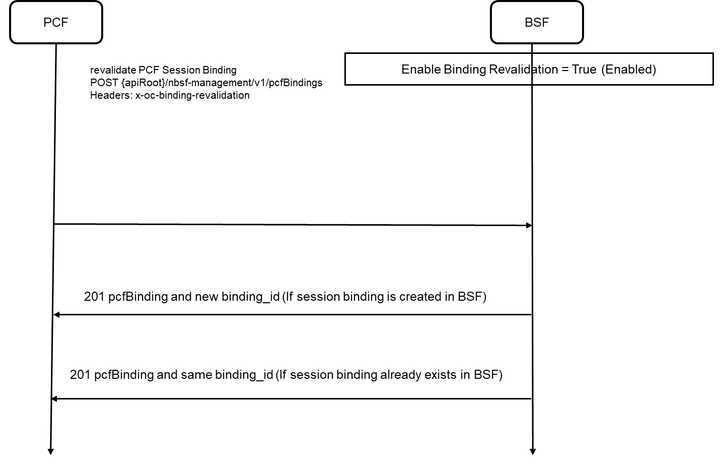
The following diagram depicts a sample call flow for revalidating the
binding information for a PDU session in BSF when the binding revalidation is
enabled in BSF and the revalidation request includes
x-oc-binding-revalidation header:
Figure 3-6 Binding revalidation in BSF
-
BSF receives a binding revalidation request for a PDU session from PCF.
-
BSF checks if the session binding revalidation is enabled in BSF and the revalidation request includes
x-oc-binding-revalidationheader. -
If the revalidation request is a duplicate or a colliding request and if the binding information for the PDU session already exists in BSF, BSF sends a 201 response code with the existing
binding_id. -
If the binding information stored in BSF differs from the details received in the request or if the binding information for the PDU session does not exist in BSF, BSF recreates the session binding record (re-registers) for the PDU session. BSF sends a 201 response code with the new
binding_id.
Managing Stale Binding Detection Audit, Report and Recover
Enable
This feature can be enabled using CNC Console for BSF as well as using REST API.
Enable using CNC Console
To enable this feature using CNC Console for BSF, configure Enable Binding Revalidation field on Management Service page under Service Configurations in CNC Console for BSF.
For more information, see Management Service.
Enable using REST API
To enable this feature using REST API, configure the
EnableBindingrevalidate parameter under Management Service
API for BSF:
{apiRoot}/oc-bsf-configuration/v1/services/managementservice.
For more information, see Management Service section in Oracle Communications Cloud Native Core, Binding Support Function REST Specification Guide.
Observability
Metrics
- ocbsf_binding_revalidation_request_total
- ocbsf_binding_revalidation_response_total
- ocbsf_binding_revalidation_pcfBinding_missing_total
For more information, see BSF Management Service.
Alerts
- BINDING_REVALIDATION_PCF_BINDING_MISSING_MINOR
- BINDING_REVALIDATION_PCF_BINDING_MISSING_MAJOR
- BINDING_REVALIDATION_PCF_BINDING_MISSING_CRITICAL
For more information, see List of Alerts.
Logging
The following logs with a specific marker "marker":{"name":"BINDING"}, "Binding Audit:<additional log text>" are generated for this feature:
- For Revalidation request, if the binding association is not present in BSF, BSF
updates its logs with the failure for the revalidation request. The updated
logs include:
- SUPI
- DNN
- S-NSSAI
- UE-IP (IPv6/IPV4)
- IPDomain if available
- PCF FQDN
- error code and cause at “WARN” level
- For revalidation request, if BSF can not reestablish or restore the
BSF binding after all session retries, BSF updates its logs with the failure for
the restoration request.
- SUPI
- DNN
- S-NSSAI
- UE-IP (IPv6/IPV4)
- IPDomain if available
- PCF FQDN
- error code and cause at “WARN” level
3.7 Traffic Segregation
This feature provides end-to-end traffic segregation to BSF based on traffic types. Within a Kubernetes cluster, traffic segregation can divide applications or workloads into distinct sections such as OAM, SBI, Kubernetes control traffic, etc. The Multus CNI container network interface (CNI) plugin for Kubernetes enables attaching multiple network interfaces to pods to help segregate traffic from each BSF microservice.
This feature addresses the challenge of logically separating IP traffic of different profiles, which are typically handled through a single network (Kubernetes overlay). The new functionality ensures that critical networks are not cross-connected or sharing the same routes, thereby preventing network congestion.
With traffic segregation, operators can segregate traffic to external feeds and applications more effectively. Previously, all external traffic was routed through the same external network, but now, egress traffic from the BSF pods can be directed through non-default networks to third-party applications. This separation is achieved by leveraging cloud-native infrastructure and the load balancing algorithms in CNE.
The feature supports the configuration of separate networks, Network Attachment Definitions (NADs), and the Cloud Native Load Balancer (CNLB). These configurations are crucial for enabling cloud native load balancing, facilitating ingress-egress traffic separation, and optimizing load distribution within BSF.
Prerequisites
The CNLB feature is only available in BSF if CNE is installed with CNLB and Multus.
Cloud Native Load Balancer (CNLB)
cnlb.ini file before installing
CNE.
Note:
CNLB is supported only for IPv4 stack.For more information about enabling and configuring CNLB, see Oracle Communications Cloud Native Core, Cloud Native Environment User Guide, and Oracle Communications Cloud Native Core, Cloud Native Environment Installation, Upgrade, and Fault Recovery Guide.
Network Attachment Definitions for CNLB
A Network Attachment Definition (NAD) is a resource used to set up a network attachment, in this case, a secondary network interface to a pod. BSF supports two types of CNLB NADs:
- Ingress Network Attachment Definitions
Ingress NADs are used to handle inbound traffic only. This traffic enters the CNLB application through an external interface service IP address and is routed internally using interfaces within CNLB networks.
- Naming
Convention:
nf-<service_network_name>-int
- Naming
Convention:
- Egress Only Network Attachment Definitions
Egress Only NADs enable outbound traffic only. An NF pod can initiate traffic and route it through a CNLB application, translating the source IP address to an external egress IP address. An egress NAD contains network information to create interfaces for NF pods and routes to external subnets.
- Requirements: Destination (egress) subnet addresses
are known beforehand and defined under the
cnlb.inifile'segress_destvariable to generate NADs. - Naming
Convention:
nf-<service_network_name>-egr
- Requirements: Destination (egress) subnet addresses
are known beforehand and defined under the
- Ingress/Egress Network Attachment Definitions
Ingress/Egress Network Attachment Definitions enable inbound/outbound traffic. An NF pod can initiate traffic and route it through a CNLB app, translating source IP address to an external egress IP address (defined under cnlb.ini file egress_addr variable). An Ingress/Egress Network Attachment Definition contains network information to create interfaces for NF pods and routes to external subnets. Even though an Ingress/Egress Network Attachment Definition enables outbound traffic, it also handles inbound traffic, so if inbound/outbound traffic is needed an Ingress/Egress Network Attachment Definition should be used.
- Requirements: Source (ingress) and destination (egress) subnet addresses are known beforehand and defined under cnlb.ini file egress_dest variable to generate Network Attachment Definitions.
- Naming
Convention:
nf-<service_network_name>-ie
Managing Ingress and Egress Traffic Segregation
Enable:
This feature is disabled by default. To enable this feature, you must configure the network attachment annotations in the custom values file.
Configuration
For more information about Traffic Segregation configuration, see " Configuring Traffic Segregation" section in Oracle Communications Cloud Native Core, Converged Binding Support Function Installation, Upgrade, and Fault Recovery Guide..
Observe
There are no Metrics, KPIs, or Alerts available for this feature.
Maintain
To resolve any alerts at the system or application level, see BSF Alerts section. If the alerts persist, perform the following:
- Collect the logs: For more information on how to collect logs, see Oracle Communications Cloud Native Core, Binding Support Function Troubleshooting Guide.
- Raise a service request: See My Oracle Support for more information on how to raise a service request.
3.8 Support for Dual Stack
- Coexistence strategy that allows hosts to reach IPv4 and IPv6.
- IP address allocation to the Kubernetes clusters during cluster creation. This allocation is applicable for all Kubernetes resources unless explicitly specified during cluster creation.
Note:
- The dual stack feature is not supported on Oracle Cloud Native Environment (CNE) but is supported on third-party CNEs.
- Operator needs to redeploy (Fresh install) the BSF to enable IP Dual Stack functionality.
Table 3-9 Preference of Deployment Mode
| Services | IPv6_Pv4 | IPv4_IPv6 | IPv6 | IPv4 |
|---|---|---|---|---|
| Internal communicating services | IPv6 (Single Stack) | IPv4 (Single Stack) | IPv6 (Single Stack) | IPv4 (Single Stack) |
| External communicating services | IPv6 preferred (Dual Stack) | IPv4 preferred (Dual Stack) | IPv6 (Single Stack) | IPv4 (Single Stack) |
Note:
Communication between services and CoreDNS, as well as the Kubernetes API, depends on the cluster's network preference.IP Address Allocation to Pods
IP:               10.xxx.xxx.xxx
IPs:
  IP:           10.xxx.xxx.xxx
  IP:           fd00::1:cxxx:bxxx:8xxx:xxxx
IP Address Allocation to Services
IP address allocation to all the BSF services, depends on the
DeploymentMode Helm parameter configuration. This Helm
parameter automatically configures IP Family Policy and IP Families
attributes for the BSF services. For more information about
DeploymentMode, see the "Customizing BSF" section in the Oracle Communications Cloud Native Core, Binding Support Function
Installation, Upgrade, and Fault Recovery Guide.
You can customize the IP address allocation to services based on the
DeploymentMode Helm parameter. Services route the traffic to
the destination endpoints based on this configuration. If the DeploymentMode
Helm parameter is set to IPv4, then IPv4 is allocated to services, and
services use IPv4 pod IPs to send the traffic to endpoints.
The following table describes how IP address allocation, IP Family
Policy, and IP Families vary based on the DeploymentMode Helm
parameter configuration for services:
Table 3-10 IP Address Allocation
| Infrastructure Preference | Application Preference (DeploymentMode Helm Parameter) | IP Family Policy Attribute | IP Families Attribute | Pod IP | Service IP | Endpoints |
|---|---|---|---|---|---|---|
| IPv4 Preferred | IPv4 | SingleStack | IPv4 | IPv4,IPv6 | IPv4 | IPv4 |
| IPv6 Preferred | IPv4 | SingleStack | IPv4 | IPv6,IPv4 | IPv4 | IPv4 |
| IPv4 Preferred | IPv6 | SingleStack | IPv6 | IPv4,IPv6 | IPv6 | IPv6 |
| IPv6 Preferred | IPv6 | SingleStack | IPv6 | IPv6,IPv4 | IPv6 | IPv6 |
| IPv4 Preferred | IPv4_IPv6 (IPv4Preferred) | RequiredDualStack | IPv4 Preferred | IPv4,IPv6 | IPv4,IPv6 | IPv4 |
| IPv6 Preferred | IPv4_IPv6 (IPv4Preferred) | RequiredDualStack | IPv4 Preferred | IPv6,IPv4 | IPv6,IPv4 | IPv4 |
| IPv4 Preferred | IPv6_IPv4 (IPv6Preferred) | RequiredDualStack | IPv6 Preferred | IPv4,IPv6 | IPv4,IPv6 | IPv6 |
| IPv6 Preferred | IPv6_IPv4 (IPv6Preferred) | RequiredDualStack | IPv6 Preferred | IPv6,IPv4 | IPv6,IPv4 | IPv6 |
Enable
Dual Stack support can be enabled by setting the global.deploymentMode parameter to IPv4_IPv6 or IPv6_IPv4 depending on the preference needed. For more information, see the Oracle Communications Cloud Native Core, Binding Support Function Installation, Upgrade, and Fault Recovery Guide.
Configure
Note:
The diam-gateway.dualStackPreferredDnsResolutionIpAddressType parameter is replaced by global.dgwRoutingMode. The diamgateway.envSupportedIpAddressType parameter is no longer applicable.
You can configure dual stack using the following parameters:
- global.deploymentMode
- global.egressRoutingMode
- global.dgwRoutingMode controls the IP address
selection for Diameter Gateway connections when DNS resolves a destination
to multiple IP address types. The supported values are
IPv4,IPv6,IPv4_IPv6, andIPv6_IPv4. The default value isIPv4_IPv6.
For more information on these parameters, see "Configuration Parameters for Dual Stack" in the Oracle Communications Cloud Native Core, Binding Support Function Installation, Upgrade, and Fault Recovery Guide.
Table 3-11 Gateway Routing Mode
| dgwRoutingMode/egressRoutingMode | Description | DNSQuery/k8s endpoints returns IPv4 address only | DNSQuery/k8s endpoints returns IPv6 address only | DNSQuery/k8s endpoints returns both IPv4 and IPv6 address |
|---|---|---|---|---|
| IPv4 | Strict IPv4 only | Gateway attempts connection towards the destination | Gateway will not initiate connection towards the destination | Gateway will pick up the IPv4 address and attempts connection toward the destination |
| IPv6 | Strict IPv6 only | Gateway will not initiate connection towards the destination | Gateway attempts connection towards the destination | Gateway will pick up the IPv6 address and attempts connection toward the destination |
| IPv4_IPv6 | Supports both with IPv4 preferred | Gateway attempts connection towards the destination | Gateway attempts connection towards the destination | Gateway will pick up the IPv4 addresses only and attempts connection toward the destination |
| IPv6_IPv4 | Supports both with IPv6 preferred | Gateway attempts connection towards the destination | Gateway attempts connection towards the destination | Gateway will pick up the IPv6 addresses only and attempts connection toward the destination |
| None (Applicable to egressRoutingMode only) | No changes. Egress Gateway will rely on library to select IPs. | NA | NA | NA |
Table 3-12 Recommended Configurations for Dual Stack and Single Stack
| Description | global.deploymentMode | global.dgwRoutingMode | global.egressRoutingMode |
|---|---|---|---|
| Configuration for IPv4 single stack mode | IPv4 | IPv4 | IPv4 |
| Configuration for IPv6 single stack mode | IPv6 | IPv6 | IPv6 |
| Configuration for dual stack mode with IPv4 preference | IPv4_IPv6 | IPv4_IPv6 | IPv4_IPv6 |
| Configuration for dual stack mode with IPv6 preference | IPv6_IPv4 | IPv6_IPv4 | IPv6_IPv4 |
| Configuration as per the cluster preference where application is deployed | ClusterPreferred | IPv4_IPv6 | None |
Note:
- Any combination of dual stack or IPv6 configurations other than recommended values shall be considered as invalid and not supported.
- Egress routing for automatic fallback between IPv4 and IPv6 is not supported. You should connect using their preferred IP address type. If that IP type is unavailable, connection to the peer is considered unavailable.
Upgrade details
During upgrade, remove the retired parameter and set
global.dgwRoutingMode to the value that matches the
required IP-family preference. If the previous value was both,
select either IPv4_IPv6 or IPv6_IPv4
explicitly. Do not use diamgateway.envSupportedIpAddressType;
it is no longer applicable.
Table 3-13 Upgrade details
| diam-gateway.dualStackPreferredDnsResolutionIpAddressType | global.dgwRoutingMode |
|---|---|
| IPv4 | IPv4 |
| IPv6 | IPv6 |
| IPv4_IPv6 | IPv4_IPv6 |
| IPv6_IPv4 | IPv6_IPv4 |
| both | IPv4_IPv6 or IPv6_IPv4 depending on the preference |
Observe
There are no Metrics, KPIs, or Alerts available for this feature.
3.9 Logging Support for Error Response
Error handling framework was introduced in earlier release of BSF as a general purpose error handling tool. This feature used the error handling framework to add more details to the error using 3GPP error response format.
BSF sends error responses to consumer NFs due to some exceptions, such as signaling, validations, and internal errors. These error responses have payloads containing the problem title, status, details, and cause of the error that are used to investigate the error. BSF has been enhanced to support logs for the error responses.
- ERROR: Error is at a service or component level and not per subscriber or call flow level.
- WARN: An error is not expected in a typical call flow, and there is a need to know if it occurred in production when troubleshooting an issue.
- INFO: Informational logs showing what is happening in each service or component during a call flow. All in-out messages to a service should be logged at INFO level. It is also beneficial to log messages once during processing by a component within a service.
- DEBUG: Provides detailed logs that helps to troubleshoot an issue.
- TRACE: Includes detailed logging of messages in and out of each component or method.
{
  “errorStatus”: “Value”, (ProblemDetails status field)
  “errorTitle”: “Value”, (ProblemDetails title field)
  “errorDetails”: “Value”, (ProblemDetails detail field)
  “errorCause”: “Value”  (ProblemDetails cause field)
  “sender”: “Value”, (nfType-nfInstanceId)
  “subscriberId”: “Value” (UE ID associated with event if present)
}
Table 3-14 General Log Format
| Parameter | Description | Example |
|---|---|---|
| errorStatus | Specifies the status code of the error. | 404, 500, etc. |
| errorTitle | Specifies the title of the error. | Required parameter in binding data is missing |
| errorDetails | Specifies the error detail produced by error
handling framework in case of BSF as producer.
Note: For errorDetails field to be populated in the required format, error handling framework should be enabled in CNC Console for the required service. |
ocbsf1-2-api-gateway.bsf1-2.svc.atlantic.morrisville.us.lab.oracle.com:BSF_MGMT:Mandatory
                                    parameter is missing in request
:EC-OBSF-BSF_MGMT-REQVLD-EI-05-02-400-00010-01-02 |
| errorCause | Specifies the cause of the error. | MANDATORY_IE_MISSING |
| sender | Specifies the sender which is composed by the nfType
plus the instanceId.
Note: In case of BSF as producer of error, the sender field will be BSF plus the instanceId of the BSF. |
BSF-fe7d992b-0541-4c7d-ab84-c6d70b1b0666 |
| subscriberId | Specifies the subscriberId which can be SUPI or GPSI associated with the event. | imsi-65008100001061 |
- If SUPI and GPSI both are present, use SUPI.
- If SUPI is not present, and GPSI is present, use GPSI.
Note:
Sender-contains the nfType-instanceIdfrom the sender of the HTTP Request. Where nfType is a value which contains the type of Network Function set as BSF by default, and nfInstanceIdis a unique identifier for a specific instance of a Network Function. This value is set in the application configuration for BSF
Support for Burst rate limit modification and customization for logs
When the enhanced error response logging feature is enabled, due to certain error scenarios volume of error logs can become huge. In order to control the volume of logs, BSF allows to add a burst filter for logging against logs for all the microservices.
The Burst filter provides a mechanism to control the rate at which LogEvents are processed by silently discarding events after the maximum limit has been reached. It enables to control the frequency and volume of warning messages generated. This ensures that excessive logging does not overwhelm the system or obscure critical information.
Configuring BurstFilter property in log4J includes the
following parameters:
Level:Determines the minimum log level at which the filter becomes active. Log events below this level are not affected.
Possible values are:OFFTRACEDEBUGINFOWARNERRORFATALALL
Default value is
DEBUG.Rate:Defines the average number of log events allowed per second. Events beyond this rate are suppressed unless allowed by
maxBurst.It accepts any positive integer or decimal value.
Default value is 500 logs per second.
maxBurst:Specifies the maximum number of log events that can be logged in a sudden spike before suppression starts. Helps tolerate short bursts without dropping all messages.
It accepts any positive integer value.
Default value is 3000.
onMismatch:Defines the filter’s behavior when a log event does not match the filter conditions such as below the level or exceeding the rate/burst limit.
Possible values are:DENY: The event is suppressed and not passed to the appender.NEUTRAL: The event is passed to the next filter in the chain for further evaluation.ACCEPT: The event is always logged regardless of conditions.
Default value is
DENY.
Managing Enhancements to Logging Support for Error Response
This section explains the procedure to enable and configure the feature.
Enable
Note:
Oracle does not recommend enabling this feature. When this feature is enabled, sensitive information in the form of UE identifier gets published. Users can secure the logs in their environment using appropriate configuration.
Configure
You can configure logging support for error response using the Enable Enhanced Logging and Enable UE Identifier Information toggle buttons. These toggle buttons are available in General Settings under General Configurations on CNC Console for BSF. For information about how to configure for BSF Management Service in CNC Console, see General Settings.
Observe
There are no new metrics in BSF Management Service for this feature.
3.10 Support for TLS
BSF uses Hypertext Transfer Protocol Secure (HTTPS) and Diameter Gateway to establish secured connections with consumer NFs and producer NFs, respectively. These communication protocols are encrypted using Transport Layer Security (TLS).
- Handshake Protocol: Exchanges the security parameters of a connection.
- Record Protocol: Receives the messages to be transmitted, fragments the data into multiple blocks, secures the records, and then transmits the result. Received data is delivered to higher-level peers.
Note:
If both TLS 1.2 and TLS 1.3 are supported, TLS 1.3 is given priority.TLS 1.2 and TLS 1.3 Handshake
Figure 3-7 TLS 1.2 and TLS 1.3 Handshake
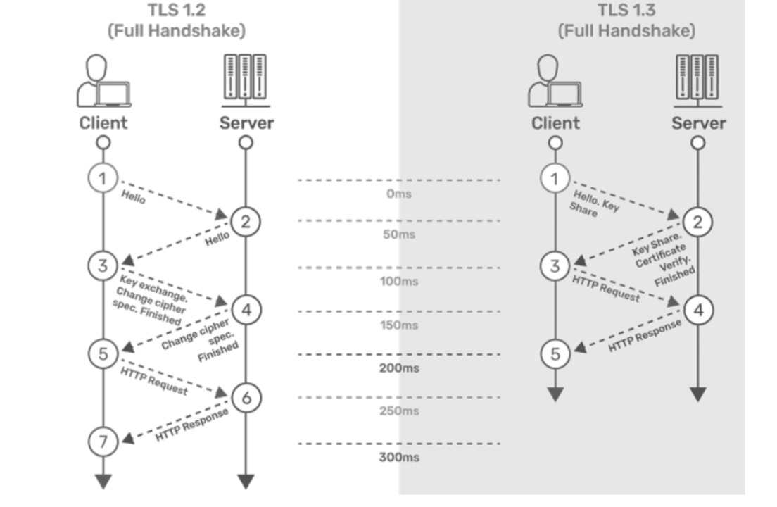
Step 1: The connection or handshake starts when the client sends a "client hello" message to the server. This message consists of cryptographic information such as supported protocols and cipher suites. It also contains a random value or random byte string.
Step 2: To respond to the "client hello" message, the server sends a 'server hello' message. This message contains the CipherSuite that the server has selected from the options provided by the client. The server also sends its certificate, along with the session ID and another random value.
Step 3: The client verifies the certificate sent by the server. When the verification is complete, it sends a byte string encrypted using the public key of the server's certificate.
Step 4: When the server receives the secret, both the client and server generate a master key along with session keys (ephemeral keys). These session keys are used for symmetrically encrypting the data.
Step 5: The client sends an "HTTP Request" message to the server to enable the server to transition to symmetric encryption using the session keys.
Step 6: To respond to the client’s "HTTP Request" message, the server does the same and switches its security state to symmetric encryption. The server concludes the handshake by sending an HTTP response.
Step 7: The client-server handshake is completed in two round trips.
TLS 1.3Step 1: The connection or handshake begins when the client sends a "client hello" message to the server, which includes the list of supported cipher suites and the client's key share for the specific key agreement protocol.
Step 2: To respond to the "client hello" message, the server sends the key agreement protocol that it has chosen. The "Server Hello" message includes the server key share, server certificate, and the "Server Finished" message.
Step 3: The client verifies the server certificate, generates keys since it has the server's key share, and then sends the "Client Finished" message along with an HTTP request.
Step 4: The server completes the handshake by sending an HTTP response.
Note:
ASM and TLS are not supported together.The following table provides comparison of TLS 1.2 with TLS 1.3:
Table 3-15 Comparison of TLS 1.2 with TLS 1.3
| Feature | TLS 1.2 | TLS 1.3 |
|---|---|---|
| TLS Handshake | This is less efficient as it requires more round-trips to complete the handshake process. | This is more efficient as it requires less round-trips to complete the handshake process. |
| Cipher Suites | This has less secured Cipher Suites. |
This has more secured Cipher Suites. They support
the following ciphers:
|
| Round-Trip Time (RTT) | This has higher RTT during TLS handshake. | This has low RTT. |
| Performance | This has higher latency during TLS handshake. | This has low latency during TLS handshake. |
Note:
- BSF does not prioritize cipher suites on the basis of priorities. To select cipher on the basis of priorities, you must write the cipher suites in the decreasing order of priority.
- BSF does not prioritize supported groups on the basis of priorities. To select supported group on the basis of priorities, you must write the supported group values in the decreasing order of priority.
-
If you want to provide values for the signature_algorithms extension using the clientSignatureSchemes parameter, the following comma-separated values must be provided to deploy the pods:
- rsa_pkcs1_sha512
- rsa_pkcs1_sha384
- rsa_pkcs1_sha256
- The mandatory extensions as listed in RFC 8446 cannot be
disabled on the client or server side. The following is the list of the
extensions that cannot be disabled:
- supported_versions
- key_share
- supported_groups
- signature_algorithms
- pre_shared_key
Table 3-16 Digital Signature Algorithms
| Algorithm | Key Size (Bits) | Elliptic Curve (EC) |
|---|---|---|
| RS256 (RSA) | 2048 | NA |
| 4096
This is the recommended value. |
NA | |
| ES256 (ECDSA) | NA | SECP384r1
This is the recommended value. |
Note:
The following functionalities from TLS 1.3 specifications are not supported:- Zero round-trip time (0-RTT) mode.
- Pre-Shared Key (PSK) exchange.
3.10.1 Support for TLS Using HTTPs
BSF uses Hypertext Transfer Protocol Secure (HTTPS) to establish secured connections with consumer NFs and producer NFs, respectively. These communication protocols are encrypted using Transport Layer Security (TLS).
Enable
This feature is enabled by default at the time of Gateway Services deployment by completing the required Helm configurations.
Configure
You can configure this feature using Helm. For information about Helm configurations, see "Global Parameters" in Oracle Communications Cloud Native Core, Binding Support Function Installation, Upgrade, and Fault Recovery Guide.
Observe
- oc_ingressgateway_incoming_tls_connections
- oc_egressgateway_outgoing_tls_connections
- security_cert_x509_expiration_seconds
For more information about metrics, see TLS Metrics section.
- CERTIFICATE_EXPIRY
- BSF_CONNECTION_FAILURE
For more information about alerts, see Configuring BSF Alerts section.
If you encounter alerts at system or application levels, see Configuring BSF Alerts section for resolution steps.
In case the alert still persists, perform the following:
- Collect the logs and Troubleshooting Scenarios: For more information on how to collect logs and troubleshooting information, see Oracle Communications Cloud Native Core, Binding Support Function Troubleshooting Guide.
- Raise a service request: See My Oracle Support for more information on how to raise a service request.
3.10.2 Support for TLS in Diameter Gateway
BSF uses Diameter Gateway to establish secured connections with consumer NFs and producer NFs, respectively. These communication protocols are encrypted using Transport Layer Security (TLS).
Enable
This feature is disabled by default. It can be enabled using TLS_ENABLED parameter using Helm configurations. For information about Helm configurations, see "Global Parameters" in Oracle Communications Cloud Native Core, Binding Support Function Installation, Upgrade, and Fault Recovery Guide.
Configure
You can configure this feature using Helm. For information about Helm configurations, see "Global Parameters" in Oracle Communications Cloud Native Core, Binding Support Function Installation, Upgrade, and Fault Recovery Guide.
Peer level support for TLS versions can be configured using CNC Console. For more information, see Peer Nodes section.
Observe
- diam_conn_network
- diam_failed_conn_network
- diam_conn_network_responder
- dgw_tls_cert_expiration_seconds
For more information about metrics, see TLS Metrics section.
- DGW_TLS_CONNECTION_FAILURE
- DIAM_GATEWAY_CERTIFICATE_EXPIRY_MINOR
- DIAM_GATEWAY_CERTIFICATE_EXPIRY_MAJOR
- DIAM_GATEWAY_CERTIFICATE_EXPIRY_CRITICAL
For more information about alerts, see Configuring BSF Alerts section.
- status_request (0x0005)
- status_request_v2 (0x0011)
- supported_groups (0x000A)
- ec_point_formats (0x000B)
- extended_master_secret (0x0017)
- session_ticket (0x0023)
- signature_algorithms (0x000D)
- signature_algorithms_cert (0x0032)
- supported_versions (0x002B)
- psk_key_exchange_modes (0x002D)
- key_share (0x0033)
- renegotiation_info (0xFF01)
If you encounter alerts at system or application levels, see Configuring BSF Alerts section for resolution steps.
In case the alert still persists, perform the following:
- Collect the logs and Troubleshooting Scenarios: For more information on how to collect logs and troubleshooting information, see Oracle Communications Cloud Native Core, Binding Support Function Troubleshooting Guide.
- Raise a service request: See My Oracle Support for more information on how to raise a service request.
3.10.3 TLS 1.3 Support for Kubernetes API Server
In a Kubernetes-based 5G Core deployment, BSF regularly interacts with the Kubernetes API server (Kube-Api-Server) to retrieve the secrets and configmap information.
With the implementation of this feature, BSF supports TLSv1.3 in addition to TLSv1.2 for establishing secure communication with the Kubernetes API server.
Managing TLS 1.3 Support for Kubernetes API Server
Enable and Configure
This feature can be enabled or disabled using kubeApiServerTlsVersion flag. If the flag is enabled, user can choose TLS 1.3 or TLS 1.2 for communication between each service and Kubernetes API server. For information, see Oracle Communications Cloud Native Core, Binding Support Function Installation, Upgrade, and Fault Recovery Guide.
Observe
There are no alerts and metrics for this feature.
3.11 Enhancements to Error Response
BSF sends error responses to consumer NFs due to some exceptions, such as signaling, validations, and internal errors. These error responses have payloads containing the problem title, status, details, and cause of the error that are used to investigate the error. The details section is now enhanced with application error IDs.
The error handling module gives provision to configure the error response dynamically and the same is responded when BSF is producer of the call flow.
With the enhanced error response mechanism, BSF sends additional information
such as server FQDN, micro-service ID, error category, and application error ID in the
detail attribute of the ProblemDetails. This
enhancement provides more information about the error and troubleshoot them.
Application error ID follows the below format.
[ EC] [NF ID] [Microservice ID] [Category] [Error ID]
An error code dictionary will be provided to identify the cause and possible solution of the error. For more details of the error code dictionaries for BSF management service, Egress Gateway, Ingress Gateway, and NRF Client, see Error Code Dictionary .
Managing Enhancements to Error Response
This section explains the procedure to enable and configure the feature.
Enable
By default, this feature is disabled. The operator can enable this feature through the CNC Console configurations.
Configure
You can configure error handling functionality under Error Handling on CNC Console for BSF. For information about how to configure for BSF Management Service in CNC Console, see Error Configurations .
Observe
- error_handler_exec_total
- error_handler_in_total
- error_handler_out_total
For more information, see BSF Management Service.
3.12 Validating Destination-Realm Attribute-Value Pair (AVP) Received in AAR-I Message
The destination-realm Attribute-Value Pair (AVP) received in the AAR-I message from an AF must be validated at the BSF Diameter Gateway before processing and forwarding the AAR-I message to a corresponding PCF instance.
Note:
This validation applies exclusively to the AAR-I message within the BSF. For subsequent AAR-U and STR messages, it is assumed that the AF will send the correct Destination-Host and the destination-realm Attribute-Value Pair (AVP) values based on the AAA response received.
Figure 3-8 Diameter Gateway for BSF
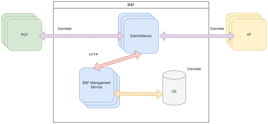
Figure 3-9 destination-realm Validation Process
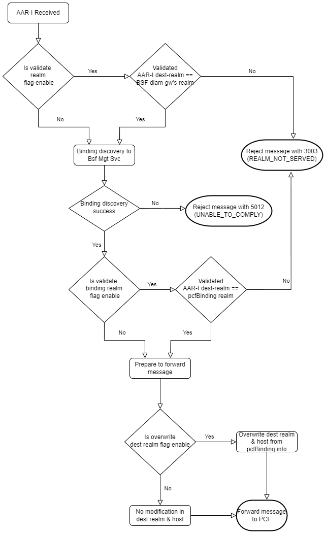
- When Diameter Gateway receives an AAR-I message from an AF, it checks if the validation realm flag is enabled.
-
If the validation realm flag is enabled, it validates the destination-realm AVP received in the AAR-I message against the BSF Diameter Gateway realm.
If the validation is successful, it proceeds with the message processing and the Diameter Gateway sends a Binding Discovery message to BSF Management Service.
If the validation fails, the Diameter Gateway rejects the AAR-I message with error code 3003 (REALM_NOT_SERVED).
Note:
The Diameter Gateway error code configuration for BSF is applicable and the default result code 3003 can be modified to any other error codes. -
If the validation realm flag is disabled, the Diameter Gateway sends a Binding Discovery message to BSF Management Service without validating the destination-realm AVP.
-
After receiving a successful response to Binding Discovery request from BSF Management service, the Diameter Gateway checks if the validate binding realm flag is enabled.
If the validate binding realm flag is enabled, the Diameter Gateway validates the destination-realm against the pcfBinding realm.
If the validation is successful, the Diameter Gateway forwards the message for further processing.
If the validation fails, the Diameter Gateway rejects the AAR-I message with error code 3003 (REALM_NOT_SERVED).
If the validate binding flag is disabled, the Diameter Gateway forwards the message for further processing without validating the destination-realm against the pcfBinding info.
- If the Binding Discovery request fails, the Diamter Gateway rejects the AAR-I message with error code 5012 (UNABLE_TO_COMPLY).
- After the successful validation of the destination-realm against
pcfBinding info, the Diameter Gateway checks if overwrite diam-realm flag is
enabled. If this flag is enabled, it overwrites the destination-realm received
in the AAR-I message with the pcfBinding info received in the binding discovery response.
Note:
If Overwrite Realm configuration is enabled, the diam_response_network metric for AAA message will show the new realm that was overwritten as the 'reqDestRealm', and not the original realm that was sent in the AAR message.
- If overwrite diam-realm flag is disabled, there is no modification made to the destination-realm.
- The message is forwarded to PCF.
Note:
Fake AVP validation will not be performed if routing table is configured. That is, if the above mentioned fake AVP parameters are configured and the routing tables are also configured, AVP validation will not be performed. The call will be processed as per the routing table configuration.
Managing Validation of destination-realm in AAR-I Message
- DIAMETER.Enable.Validate.Realm
- DIAMETER.BSF.Enable.Validate.Binding.Realm
- DIAMETER.BSF.Enable.Overwrite.Realm
For more details on the above mentioned advanced settings keys, see Settings.
Observability
Metrics
ocbsf_diam_realm_validation_failed_total metric is used to count the number of failed destination-realm validation at Diameter Gateway for BSF. For more details, see Diameter Gateway Metrics.
Alerts
3.13 Support for Automated Certificate Lifecycle Management
Public Key Interface (PKI) is the set of elements such as public/private keys, certificate signing request, and certificates that are required to handle secure communications and transactions. BSF uses secure protocols for its communications, such as HTTPS and Secure Socket Layer (SSL) / Transport Layer Security (TLS) technologies to handle these secure communications. This is achieved with the use of Public and Private Keys, and the presence of trusted authorities, also known as Certificate Authorities (CA), which create and issue certificates. These certificates have a determined validity period. These certificates must be renewed before expiry. They can also be revoked when the CA or its keys are compromised. These certificates must be recreated when required.
This feature enables BSF to support automation of certificate lifecycle management in integration with Oracle Communications Cloud Native Core, Certificate Manager (OCCM).
OCCM provides the option to automatically create, renew, and delete certificates for a given CA, with the possibility to track previously created certificates and renew/delete them when required.
The certificate lifecycle management includes:
- Certificate Creation,
- Certificate Deletion,
- Certificate Monitoring (including the ones that were created using a different tool from OCCM),
- Certificate Renewal.
Note:
OCCM does not support OAuth token generation and distribution (currently handled by NRF) used for SBI signalling.
Figure 3-10 BSF Integration with OCCM
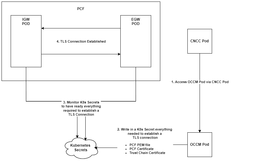
There is no direct communication between OCCM and BSF. All the communications are handled using Kubernetes Secrets.
All the required certificates are configured using OCCM.
After OCCM creates these Kubernetes Secrets, or monitors the already existing ones, the Ingress and Egress Gateways monitor these Secrets and keep track of their current status:
- VALID: A Kubernetes Secret which holds a certificate that has not expired and it is properly signed
- EXPIRED: A Kubernetes Secret which holds a certificate that has
met its expiration date (the value determined in its
notAftervalue) - MISSING: A Kubernetes Secret which has its certificate missing, or any other essential file for the TLS/SSL bundle
- CORRUPT: A Kubernetes Secret which has its certificate corrupt, either invalid file, invalid signature, or invalid format
Managing the keys and certificates
Install Guide Considerations
- Upgrade: When BSF is deployed with OCCM, follow the specific upgrade sequence as mentioned in the Oracle Communications, Cloud Native Core Solution Upgrade Guide.
- Rollback: You can remove Kubernetes secrets if the current version
of BSF does not use that secret by checking the
ocbsf_custom_values.yamlfile. Before deleting, please make sure that there is no plan to rollback to the BSF version which uses these secrets. Otherwise Rollback will fail. For more information on migrating the secrets from BSF to OCCM and removal of Kubernetes secrets from the yaml file, see Upgrade Strategy in Oracle Communications Cloud Native Core, Binding Support Function Installation, Upgrade, and Fault Recovery Guide.
Configure
- ingress-gateway.enableIncomingHttps
- ingress-gateway.service.ssl.privateKey.k8SecretName
- ingress-gateway.service.ssl.privateKey.k8NameSpace
- ingress-gateway.service.ssl.privateKey.rsa.fileName
- ingress-gateway.service.ssl.certificate.k8SecretName
- ingress-gateway.service.ssl.certificate.k8NameSpace
- ingress-gateway.service.ssl.certificate.rsa.fileName
- ingress-gateway.service.ssl.caBundle.k8SecretName
- ingress-gateway.service.ssl.caBundle.k8NameSpace
- ingress-gateway.service.ssl.caBundle.fileName
- ingress-gateway.service.ssl.keyStorePassword.k8SecretName
- ingress-gateway.service.ssl.keyStorePassword.k8NameSpace
- ingress-gateway.service.ssl.keyStorePassword.fileName
- ingress-gateway.service.ssl.trustStorePassword.k8SecretName
- ingress-gateway.service.ssl.trustStorePassword.k8NameSpace
- ingress-gateway.service.ssl.trustStorePassword.fileName
For more information, see Basic Configurations in Ingress Gateway section in Oracle Communications Cloud Native Core, Binding Support Function Installation, Upgrade, and Fault Recovery Guide.
- egress-gateway.enableOutgoingHttps
- egress-gateway.egressGwCertReloadEnabled
- egress-gateway.egressGwCertReloadPath
- egress-gateway.service.ssl.privateKey.k8SecretName
- egress-gateway.service.ssl.privateKey.k8NameSpace
- egress-gateway.service.ssl.privateKey.rsa.fileName
- egress-gateway.service.ssl.privateKey.ecdsa.fileName
- egress-gateway.service.ssl.certificate.k8SecretName
- egress-gateway.service.ssl.certificate.k8NameSpace
- egress-gateway.service.ssl.certificate.rsa.fileName
- egress-gateway.service.ssl.certificate.ecdsa.fileName
- egress-gateway.service.ssl.caBundle.k8SecretName
- egress-gateway.service.ssl.caBundle.k8NameSpace
- egress-gateway.service.ssl.caBundle.fileName
- egress-gateway.service.ssl.keyStorePassword.k8SecretName
- egress-gateway.service.ssl.keyStorePassword.k8NameSpace
- egress-gateway.service.ssl.keyStorePassword.fileName
- egress-gateway.service.ssl.trustStorePassword.k8SecretName
- egress-gateway.service.ssl.trustStorePassword.k8NameSpace
- egress-gateway.service.ssl.trustStorePassword.fileName
For more information, see Basic Configurations in Egress Gateway section in Oracle Communications Cloud Native Core, Binding Support Function Installation, Upgrade, and Fault Recovery Guide.
Observability
Monitoring the keys and certificates
BSF supports monitoring and automatic renewal of its' TLS certificates in integration with OCCM.
It is validated that the renewed certificate and key are picked up for any new TLS connections.
Also, the existing TLS connections using the previous key and certificate are gracefully brought down.
Clean up of the certificates are also handled through OCCM.
For information about enabling HTTPS, see Configuring Secrets for Enabling HTTPS in Oracle Communications Cloud Native Core, Binding Support Function Installation, Upgrade, and Fault Recovery Guide.
.
Metrics
The oc_certificatemanagement_tls_certificate_info metric is used to support automated certificate lifecycle management.
For more information, see Metrics for Automated Certificate Lifecycle Management.
3.14 Support for cnDBTier APIs in CNC Console
Note:
This cnDBTier APIs can be accessed only through CNC Console.- Backup List: This API displays the details of stored backups, such as the ID and size of the backup.
- cnDBTier Backup Status: This API checks the cnDBTier backup status.
- Database Statistics Report: This API displays the number of available database.
- Georeplication Status:
- Real Time Overall Replication Status: This API displays the overall replication status in multisite deployments. For example, in a four-site deployment, it provides the replication status between the following sites: site1-site2, site1-site3, site1-site4, site2-site3, site2-site4, and site2-site1. This is applicable for all other sites.
- Site Specific Real Time Replication Status: This API displays the site-specific replication status.
- Georeplication Status Across All Sites: This API is used to retrieve the georeplication status across all the configured sites, offering a consolidated view of the overall replication status.
- cnDBTier Health: This API displays the health status of the following
services:
- Replication Health Status: This API displays the health status of the
replication service. It checks the following:
- if the replication service is up or not
- if the replication service can connect to database or not
- Monitor Health Status: This API displays the health status of the
monitor service. It checks the following:
- if the monitor service is up or not
- if the service can connect to database or not
- if the metrics are fetched or not (the metrics are fetched when the service is up and vice versa)
- if the pod is connected to PVC or not
- if the pods status is up or not
Note:
PVC Health Status attribute is set to NA when some of the database pods are not connected to the PVC.- Backup Manager Health Status: This API displays the health status of
the backup manager service. It checks the following:
- if the backup manager service is up or not
- if the service can connect to database or not
- Replication Health Status: This API displays the health status of the
replication service. It checks the following:
- HeartBeat Status: This API displays the connectivity status between the local site and the remote site to which BSF is connected.
- IP Family Switch Over: This API is used to configure or update the preferred IP family (IPv4 or IPv6) used for communication between the replication channels.
- Georeplication Recovery: This API provides the
recovery status of georeplication for the cnDBTier cluster:
- Update Cluster As Failed: This API is used to mark a disrupted cluster as failed.
- Start Georeplication Recovery: This API is used to start the georeplication recovery process.
- Georeplication Recovery Status: This API is used to monitor the recovery status of georeplication for both FAILED and ACTIVE cnDBTier sites.
- Local Cluster Status: This API displays the status of the local cluster.
- On Demand Backup: This API provides options to initiate as well as the display the status of the on-demand backup. It also displays the status of initiated on-demand backups.
- Version: This API displays the cnDBTier version.
- Gracefully Start Georeplication: This API is used to initiate the georeplication between a primary site and one or more remote sites.
- Gracefully Stop Georeplication: This API is used to stop georeplication between a primary site and specified remote sites.
Managing cnDBTier Functionalities at CNC Console
This feature is enabled automatically when cnDBTier is configured as an instance during the CNC Console deployment. For more information about integrating cnDBTier APIs in CNC Console, see Oracle Communications Cloud Native Core, cnDBTier User Guide.
Configure
You can view cnDBTier APIs in CNC Console in the Viewing cnDBTier APIs in CNC Console section.
Maintain
If you encounter alerts at the system level, see the BSF Alerts section for resolution steps.
In case the alerts persist, perform the following tasks:
- Collect the logs: For information about how to collect logs, see Oracle Communications Cloud Native Core, Binding Support Function Troubleshooting Guide.
- Raise a service request: For information about how to raise a service request, see My Oracle Support.
3.15 Diameter Session Retry
BSF Diameter gateway sends Authorization-Authentication Request (AAR) and Session Termination Request (STR) messages to the PCF Diameter gateway, and Re-Authorization Request (RAR), and Abort Session Request (ASR) messages to P-CSCF (AF). These requests are acknowledged by corresponding response messages such as Authorization-Authentication Answer (AAA), Session Termination Answer (STA), Re-Authorization Answer (RAA), and Abort Session Answer (ASA), indicating either success or failure.
If BSF Diameter gateway receives messages such as Authorization-Authentication Answer (AAA), Re-Authorization Answer (RAA), (Session Termination Answer) STA or Abort Session Answer (ASA) with errors like 5012 (DIAMETER_UNABLE_TO_COMPLY) or any other error code or a session timeout then the CNC console has configurations that can be used to resend this failed message to a different/alternate PCF Diameter gateway, or to resend the message to the same destination through an alternate routing path (for example, via a different DRA peer). This enables two retry methods: retry to an alternate destination peer or retry to the same destination using an alternate intermediate peer.
The BSF Diameter gateway, on receiving a failed message from the Diameter Routing Agent (DRA), captures the error context and details. These error details are passed to the error handling framework implemented within the Diameter gateway. The framework determines the appropriate action such as retrying the message on an alternate route or peer based on configurations defined by the user in the CNC Console.
The Diameter message retry feature supports both direct connectivity and routing through Diameter Routing Agent (DRA) peers. When BSF is directly connected to PCF / P-CSCF, retries can be performed to alternate destination peers. When routing is performed through DRA peers (using FQDN), retries can be performed to the same destination through an alternate DRA peer.
If the Error Handler was previously enabled for AAR, it will also be enabled for RAR, ASR and STR after an upgrade. It can be disabled through the configuration screen by going to the specific message. Diameter message retry is enabled through the Error Mapping Framework feature in BSF for Rx interface messages, including AAR, STR, RAR, and ASR. This framework resolves application errors and takes necessary actions based on the error context. It attempts to find alternate solutions using the configurations provided in the CNC Console. If the error is resolved, a success response is returned to the caller; otherwise, the framework retries the request based on the configured maximum number of attempts or stops processing by forwarding the last known error.
The operator should have configured a host and realm in the diameter routing table to retry sending the failed diameter messages. Diameter gateway finds the alternate peer from the routing table. If the diameter routing table is not configured, then there is no retry behavior.
When selecting an alternate peer for a retry, the Diameter Gateway evaluates matching Diameter Routing Table entries based on the configured Priority value. The route entry with the lowest numerical priority value is considered first.
By default, the diameter message retry behavior is disabled for Rx interface. The operator can enable this feature through the CNC Console configurations.
Note:
Default number of retry attempts is 1. The number of retries can be any positive integer (>=1).BSF retries re-sending failed Diameter messages (Rx AAR, Rx STR, Rx RAR, and Rx ASR) for configured Diameter result codes, except 2xxx result codes. The 2xxx result code series represents successful responses and is not supported for retry configuration. Retry is also supported for response timeout scenarios.
Retry Attempts
The user configures the number of retries to be performed for Rx AAR, Rx STR, Rx RAR and Rx ASR diameter messages in the CNC Console. The retry attempt happens only when the alternate peers are available. If alternate peers are not available, then there is no retry attempt made. The value for number of retries can be any positive integer (>=1). There is no explicit maximum limit. It can go up to the value of Integer.MAX_VALUE.If a value less than 1 is configured, the system treats it as 1.
DIAMETER.ErrorHandler.MaxRetryCount.Rx.AARDIAMETER.ErrorHandler.MaxRetryCount.Rx.STRDIAMETER.ErrorHandler.MaxRetryCount.Rx.RARDIAMETER.ErrorHandler.MaxRetryCount.Rx.ASR
Peer Cycle Back Retry
In case the configured number of retry count is more than the total available alternate peers, the user can configure to cycle back the alternate peers. The user configures this in the CNC Console by setting the retry peer cycle back field to true. This field value can be either true or false.
DIAMETER.ErrorHandler.CycleBackRetry.Rx.AARDIAMETER.ErrorHandler.CycleBackRetry.Rx.STRDIAMETER.ErrorHandler.CycleBackRetry.Rx.RARDIAMETER.ErrorHandler.CycleBackRetry.Rx.ASR
If advanced settings configuration are not supported in the CNC Console, then the default peer cycle back retry is false.
For Example: Number of configured retry = 2 and only 2 PCF (PCF1, PCF2) Diameter gateway are configured as alternate peers in BSF.
If Rx AAR message was sent BSF - PCF1 Diameter gateway and the response has failed error code such as timeout/3002/3004.
Then the first retry uses BSF - PCF2-Diam-Gateway and the response has failed error code such as timeout/3002/3004.
Then the second retry uses BSF - PCF1-Diam-Gateway and thus uses the peer cycle back retry mechanism.
Similarly, the same peer cycle back retry behavior is applicable for Rx STR, Rx RAR, and Rx ASR messages when retries are configured for those message types.
Error Originator Peer
Error Response Originator field in the CNC Console and the customizing options are based on:
- The error received from an intermediate peer (INTERMEDIATE PEER).
- The error received from the destination peer, which is not an intermediate peer (DESTINATION PEER).
- The error received from any peer (ANY).
By default the error originator peer option is any
peer.
In response timeout cases the error originator option is not available since the origination of error cannot be found.
Call Flows in Diameter Session Retry
Call Flow of Rx AAR Existing Success or Failed Case - When Binding is Found
Figure 3-11 Rx AAR Existing Success/Failed Case - When Binding is Found
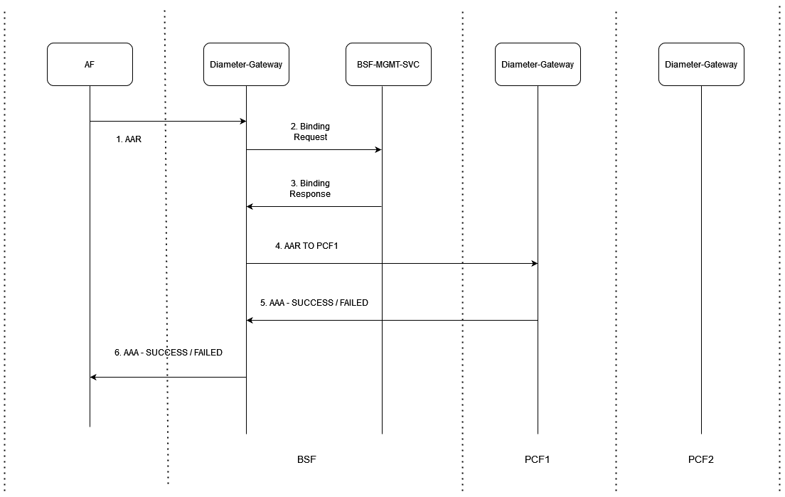
- Application Function (AF) sends AAR request to BSF Diameter Gateway.
- BSF Diameter Gateway sends binding request to BSF Management Service.
- BSF Management service sends back binding response.
- BSF Diameter Gateway sends AAR request to PCF1 Diameter Gateway.
- PCF1 Diameter Gateway may send either a successful or failed AAA response and BSF Diameter Gateway do not handle the failed response.
Call Flow of Rx AAR No Retry Case - When Binding is Not Found
Figure 3-12 Rx AAR No Retry Case - When Binding is Not Found
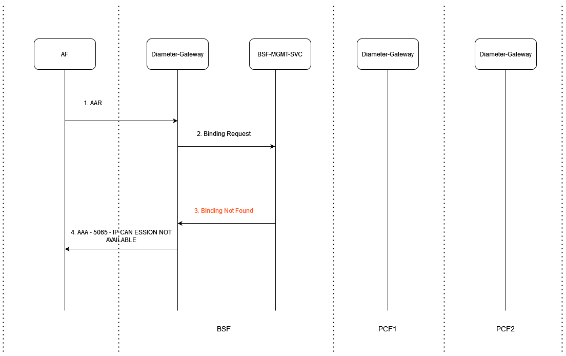
- Application Function (AF) sends AAR request to BSF Diameter Gateway.
- BSF Diameter Gateway sends binding request to BSF Management Service.
- BSF Management service sends "Binding not found" response.
- BSF Diameter Gateway responds to AF with error code 5065 (IP-CAN_SESSION_NOT_AVAILABLE).
Call Flow of Rx AAR Retry Case - When No Binding Request
Figure 3-13 Rx AAR Retry Case - When No Binding Request
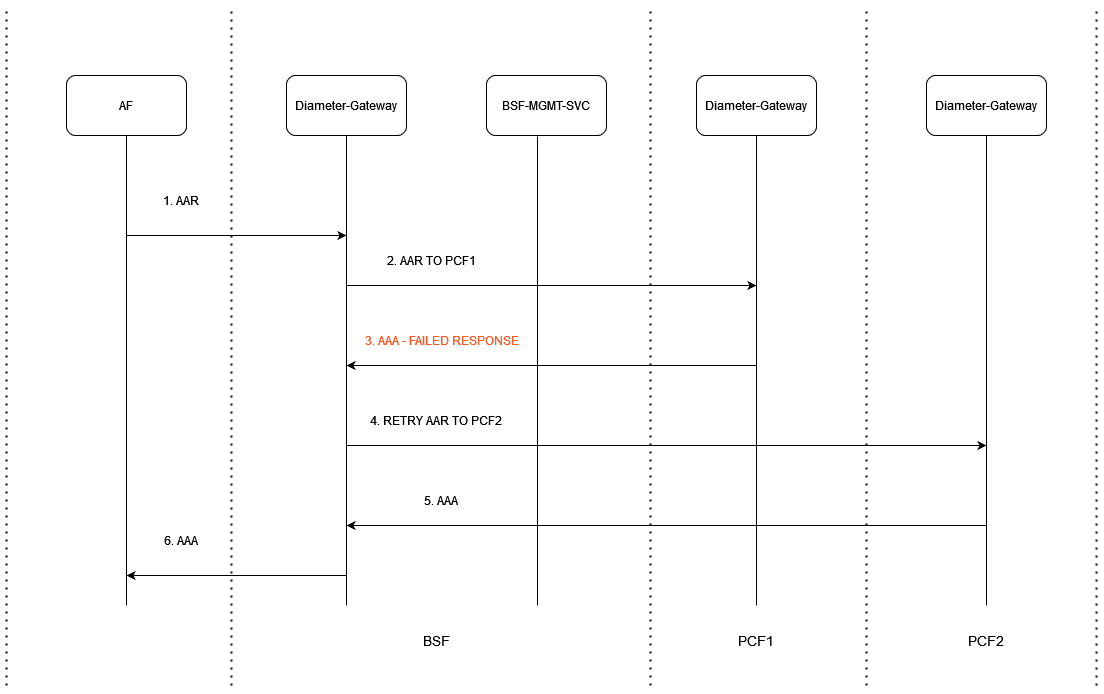
- Application Function (AF) sends AAR request to BSF Diameter Gateway.
- BSF Diameter Gateway sends AAR request to PCF1 Diameter Gateway.
- PCF1 Diameter Gateway sends a failed AAA response to BSF Diameter Gateway.
- BSF Diameter Gateway retries the AAR message to PCF2 Diameter Gateway.
- PCF2 Diameter Gateway sends a successful AAA response to BSF Diameter Gateway.
- BSF Diameter Gateway sends this AAA message to AF.
Call Flow of RX-AAR / RX-STR Retry - Success Case
Figure 3-14 RX-AAR / RX-STR Retry - Success Case
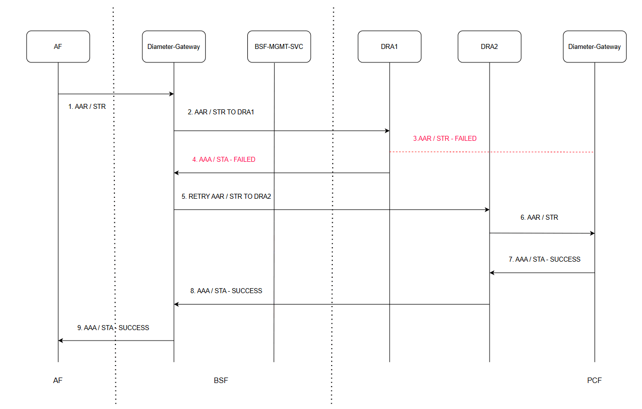
- AF sends an AAR or STR request to the Diameter Gateway.
- The Diameter Gateway forwards the AAR or STR request to DRA1.
- DRA1 fails to process the AAR or STR request.
- DRA1 returns a failed AAA or STA response to the Diameter Gateway.
- The Diameter Gateway retries the AAR or STR request through DRA2.
- DRA2 forwards the AAR or STR request to the Diameter Gateway on the PCF side.
- The PCF-side Diameter Gateway processes the request successfully and returns a successful AAA or STA response to DRA2.
- DRA2 sends the successful AAA or STA response to the Diameter Gateway.
- The Diameter Gateway returns the successful AAA or STA response to the AF.
Call Flow of RX-AAR / RX-STR Retry - Inter-Pod Routing Case
This call flow describes how the Diameter Gateway handles AAR or STR request failures when direct connectivity to a target DRA is unavailable. The request is first rerouted between Diameter Gateway pods using inter-pod routing. After the initial request sent through DRA1 fails, the Diameter Gateway retries the request through DRA2. The retry succeeds, and the successful AAA or STA response is returned back to the AF.RX-AAR / RX-STR Retry - Inter-Pod Routing Case
Figure 3-15 RX-AAR / RX-STR Retry - Inter-Pod Routing Case
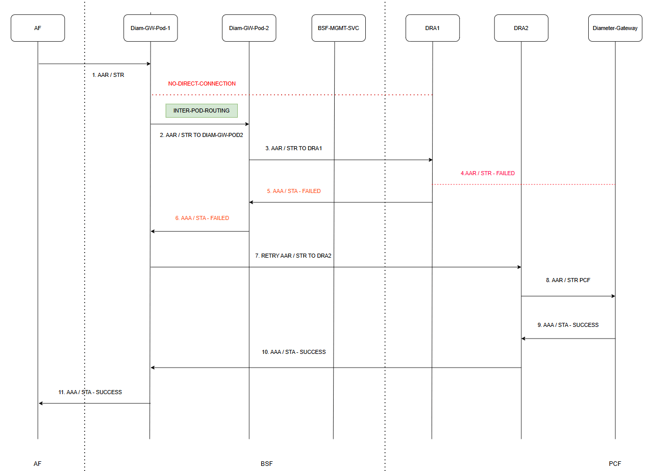
- AF sends an AAR or STR request to Diameter Gateway Pod-1.
- Diameter Gateway Pod-1 detects that direct connectivity is unavailable.
- Diameter Gateway Pod-1 forwards the request to Diameter Gateway Pod-2 using inter-pod routing.
- Diameter Gateway Pod-2 forwards the AAR or STR request to DRA1.
- DRA1 fails to process the AAR or STR request.
- DRA1 returns a failed AAA or STA response to Diameter Gateway Pod-2.
- Diameter Gateway Pod-2 forwards the failed AAA or STA response to Diameter Gateway Pod-1.
- Diameter Gateway Pod-1 retries the AAR or STR request through DRA2.
- DRA2 forwards the AAR or STR request to the Diameter Gateway on the PCF side.
- The PCF-side Diameter Gateway processes the request successfully and returns a successful AAA or STA response to DRA2.
- DRA2 forwards the successful AAA or STA response to Diameter Gateway Pod-1.
- Diameter Gateway Pod-1 returns the successful AAA or STA response to the AF.
Call Flow of RX-RAR / RX-ASR Existing - Failed Case
This call flow describes the handling of failed RAR or ASR requests between the PCF, BSF, DRA, and AF components. The PCF-side Diameter Gateway initiates a RAR or ASR request toward the AF through the BSF-side Diameter Gateway and DRA1. When the request processing fails, the failure response is sent back through the signaling path to the originating Diameter Gateway.
Figure 3-16 RX-RAR / RX-ASR Existing - Failed Case
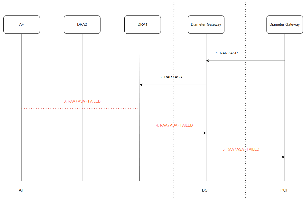
- The PCF-side Diameter Gateway sends a RAR or ASR request to the BSF-side Diameter Gateway.
- The BSF-side Diameter Gateway forwards the RAR or ASR request to DRA1.
- DRA1 fails to process the RAR or ASR request.
- DRA1 returns a failed RAA or ASA response to the BSF-side Diameter Gateway.
- The BSF-side Diameter Gateway forwards the failed RAA or ASA response to the PCF-side Diameter Gateway.
Call Flow of RX-RAR / RX-ASR Retry - Success Case
This call flow describes the retry and failover handling mechanism for Diameter RAR or ASR requests between the PCF, BSF, DRA, and AF components. When the initial RAR or ASR request sent through DRA1 fails, the BSF-side Diameter Gateway retries the request through DRA2. The retry request successfully reaches the AF, and the successful RAA or ASA response is sent back to the PCF-side Diameter Gateway.
Figure 3-17 RX-RAR / RX-ASR Retry - Success Case
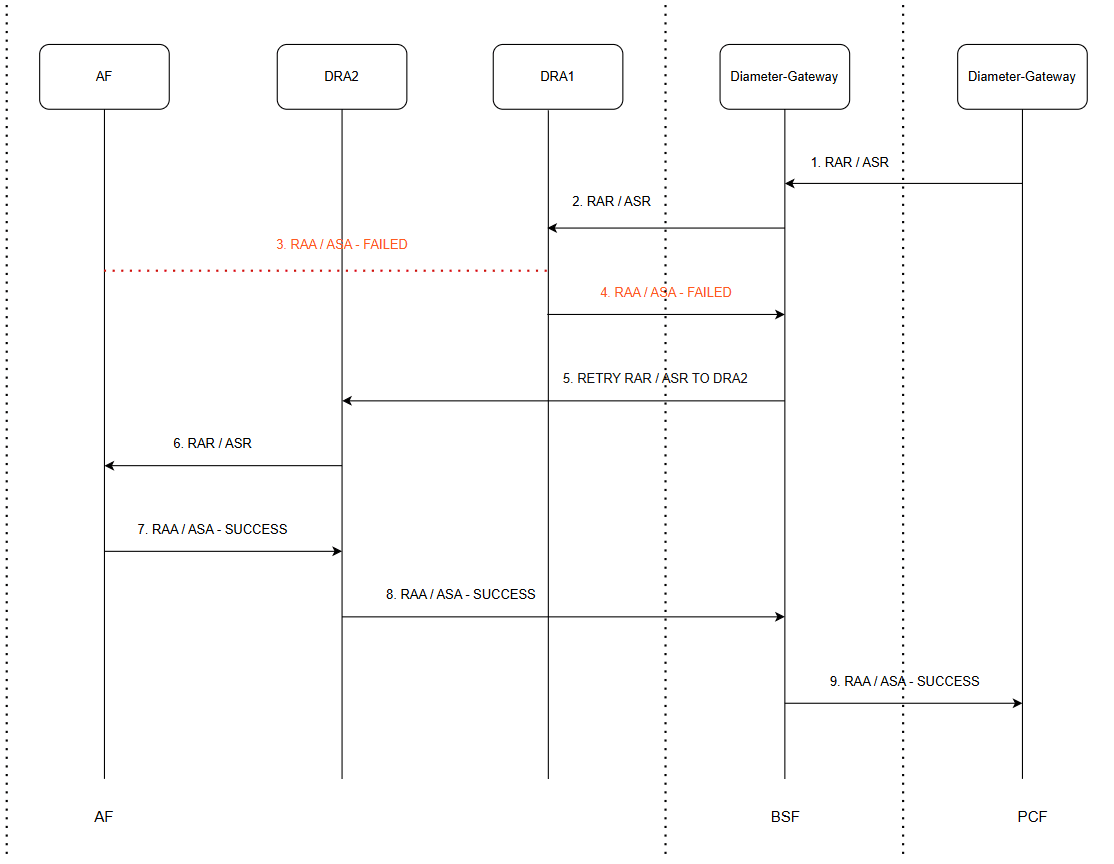
- The PCF-side Diameter Gateway sends a RAR or ASR request to the BSF-side Diameter Gateway.
- The BSF-side Diameter Gateway forwards the RAR or ASR request to DRA1.
- DRA1 fails to process the RAR or ASR request.
- DRA1 returns a failed RAA or ASA response to the BSF-side Diameter Gateway.
- The BSF-side Diameter Gateway retries the RAR or ASR request through DRA2.
- DRA2 forwards the RAR or ASR request to the AF.
- The AF processes the request successfully and returns a successful RAA or ASA response to DRA2.
- DRA2 forwards the successful RAA or ASA response to the BSF-side Diameter Gateway.
- The BSF-side Diameter Gateway forwards the successful RAA or ASA response to the PCF-side Diameter Gateway.
Call Flow of RX-RAR / RX-ASR Retry - Inter-Pod Routing Case
This call flow describes the retry and failover handling mechanism for Diameter RAR or ASR requests when the initial request sent through DRA1 fails and the selected alternate DRA peer, DRA2, is not directly reachable from Diameter Gateway Pod-1. In this case, Diameter Gateway Pod-1 uses inter-pod routing to forward the retry request to Diameter Gateway Pod-2, which can reach DRA2. The retry request is then sent through DRA2, successfully reaches the AF, and the successful RAA or ASA response is sent back to the PCF-side Diameter Gateway.
Figure 3-18 RX-RAR / RX-ASR Retry - Inter-Pod Routing Case

- The PCF-side Diameter Gateway sends a RAR or ASR request to Diameter Gateway Pod-1.
- Diameter Gateway Pod-1 forwards the RAR or ASR request to DRA1.
- DRA1 fails to process the RAR or ASR request.
- DRA1 returns a failed RAA or ASA response to Diameter Gateway Pod-1.
- After the failed RAA or ASA response from DRA1, Diameter Gateway Pod-1 selects DRA2 as the alternate DRA peer. Since Diameter Gateway Pod-1 cannot directly reach DRA2, it initiates inter-pod routing to Diameter Gateway Pod-2.
- Diameter Gateway Pod-2 retries the RAR or ASR request through DRA2.
- DRA2 forwards the RAR or ASR request to the AF.
- The AF processes the request successfully and returns a successful RAA or ASA response to DRA2.
- DRA2 forwards the successful RAA or ASA response to Diameter Gateway Pod-2.
- Diameter Gateway Pod-2 forwards the successful RAA or ASA response to Diameter Gateway Pod-1.
- Diameter Gateway Pod-1 forwards the successful RAA or ASA response to the PCF-side Diameter Gateway.
Call Flow of RX-AAR / RX-STR Retry without FQDN Peers - BSF Directly Connected to PCFs
This call flow describes the retry handling mechanism for Diameter AAR or STR requests between AF, BSF, and PCF components. The initial request sent to PCF1 fails and returns an unsuccessful AAA or STA response. The BSF-side Diameter Gateway retries the request to an alternate PCF instance, PCF2. The retry succeeds, and the successful AAA or STA response is returned to the AF.
Figure 3-19 RX-AAR / RX-STR Retry without FQDN Peers - BSF Directly Connected to PCFs
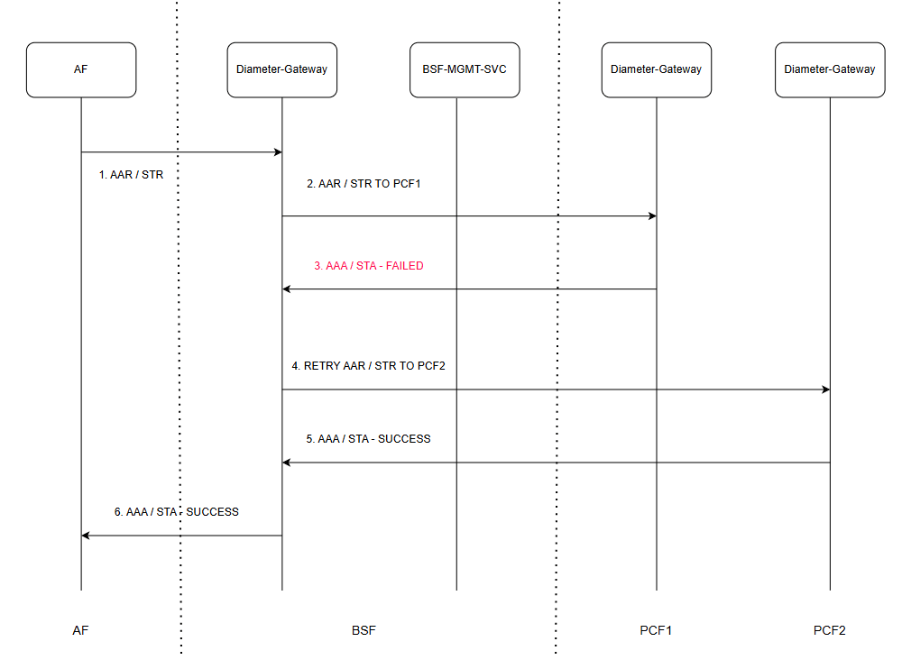
- AF sends an AAR or STR request to the BSF-side Diameter Gateway.
- The BSF-side Diameter Gateway forwards the AAR or STR request to PCF1.
- PCF1 returns a failed AAA or STA response to the BSF-side Diameter Gateway.
- The BSF-side Diameter Gateway retries the AAR or STR request to PCF2.
- PCF2 processes the request successfully and returns a successful AAA or STA response to the BSF-side Diameter Gateway.
- The BSF-side Diameter Gateway forwards the successful AAA or STA response to the AF.
Call Flow of RX-RAR / RX-ASR Retry without FQDN Peers - BSF Directly Connected to AFs
This call flow describes the retry handling mechanism for Diameter RAR or ASR requests between PCF, BSF, and AF components. The PCF-side Diameter Gateway initially sends the request to AF1, but AF1 returns a failed RAA or ASA response. The BSF-side Diameter Gateway retries the request to an alternate AF instance, AF2. The retry succeeds, and the successful RAA or ASA response is returned back to the PCF-side Diameter Gateway.
Figure 3-20 RX-RAR / RX-ASR Retry without FQDN Peers - BSF Directly Connected to AFs
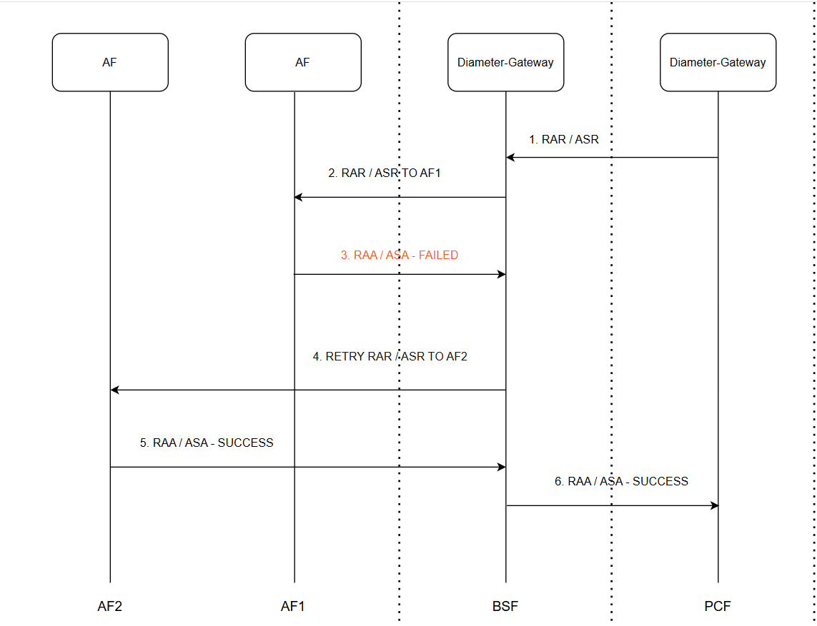
- The PCF-side Diameter Gateway sends a RAR or ASR request to the BSF-side Diameter Gateway.
- The BSF-side Diameter Gateway forwards the RAR or ASR request to AF1.
- AF1 returns a failed RAA or ASA response to the BSF-side Diameter Gateway.
- The BSF-side Diameter Gateway retries the RAR or ASR request to AF2.
- AF2 processes the request successfully and returns a successful RAA or ASA response to the BSF-side Diameter Gateway.
- The BSF-side Diameter Gateway forwards the successful RAA or ASA response to the PCF-side Diameter Gateway.
Default Error Handling Configuration
BSF provides the default error handling configuration to retry on all error codes (except diameter result code 2xxx) and timeout for Rx AAR, Rx-STR, Rx-RAR and Rx-ASR failed diameter messages. When the diameter message retry feature is enabled on Rx interface, these default error handling configurations get applied by default. The user has an option to enable/disable these default configurations through the CNC Console edit configurations.
For all default error handling configurations, the value for retry attempt is 1 and the default action is ONE_RETRY_TO_ALTERNATE_PEER. The default value for peer cycle back retry is false.
Upgrade Impact
- If the Error Handler Configuration was enabled in a previous version, then the default error handling configurations for Rx RAR, Rx STR, and Rx ASR messages are automatically enabled as part of the current version, since the feature is enabled. If the user wants to disable retry for Rx RAR, Rx STR, and Rx ASR messages, the user can do so manually by setting the Error Rule Enabled field to false for the respective error rule.
- The system restricts the configuration of 2xxx series error codes, as these represent success status codes. The error code must be a 4-digit combination of numbers and wildcard (*) characters, and 2xxx series codes are not allowed. If a 2xxx series error code was configured for AAR messages in a previous version, it is retained after upgrade. However, if such a configuration is exported and then imported, the import operation results in a PARTIAL_SUCCESS status, as 2xxx series codes are not supported during import. No other validation is applied to the status codes.
Managing Diameter Session Retry
This section explains the procedure to enable and configure the feature.
Enable
By default, Diameter Message Retry behavior is disabled for Rx interface and operator can enable this feature through the CNC Console configurations.
Configure Using CNC Console
Perform the feature configurations in CNC Console as described in Error Configurations section.
To enable over-writing of destination host on retry message, DIAMETER.ErrorHandler.Enable.UpdateDestinationHost key must be set to true in the Advanced Settings. For more information, see Settings.
Configure Using REST API
Perform the export/import error configurations as described in "Error Configurations" section in Oracle Communications Cloud Native Core, Binding Support Function REST Specification Document.
Observe
Observability
Metrics
retry and
retryReason dimensions in the Diameter Gateway Metrics section:
ocbsf_diam_request_network_totalocbsf_diam_request_inter_total
Alerts
- AAA_RX_FAIL_COUNT_EXCEEDS_CRITICAL_THRESHOLD
- AAA_RX_FAIL_COUNT_EXCEEDS_MAJOR_THRESHOLD
- AAA_RX_FAIL_COUNT_EXCEEDS_MINOR_THRESHOLD
- RAA_RX_FAIL_COUNT_EXCEEDS_CRITICAL_THRESHOLD
- RAA_RX_FAIL_COUNT_EXCEEDS_MAJOR_THRESHOLD
- RAA_RX_FAIL_COUNT_EXCEEDS_MINOR_THRESHOLD
- STA_RX_FAIL_COUNT_EXCEEDS_CRITICAL_THRESHOLD
- STA_RX_FAIL_COUNT_EXCEEDS_MAJOR_THRESHOLD
- STA_RX_FAIL_COUNT_EXCEEDS_MINOR_THRESHOLD
- ASA_RX_FAIL_COUNT_EXCEEDS_CRITICAL_THRESHOLD
- ASA_RX_FAIL_COUNT_EXCEEDS_MAJOR_THRESHOLD
- ASA_RX_FAIL_COUNT_EXCEEDS_MINOR_THRESHOLD
If you encounter alerts at system or application levels, see BSF Alerts section for resolution steps.
- Collect the logs: For more information on how to collect logs, see Oracle Communications Cloud Native Core, Binding Support Function Troubleshooting Guide.
- Raise a service request: See My Oracle Support for more information on how to raise a service request.
3.16 Support for BSF Status on NRF on CNC Console
CNC Console for BSF shows health status information of BSF and other producer NF instances related to BSF. It provides a consolidated status of the BSF instances registered with NRF.
BSF CNC Console has a new BSF NRF Status page, added under Status and Query page. This page provides the consolidated status of BSF instances registered with NRF. The user can also see the health status of primary and secondary NRF instances, or the alternate NRF.
Managing Support for BSF status on NRF on CNC Console
Enable
BSF Status on NRF feature uses NRF Client service. Hence ensure that the NRF Client
service is enabled by setting the value
global.nrfClientNfManagementEnable as
true.
For more information on NRF Client configurations, see Configuring NRF Client section in Oracle Communications Cloud Native Core, Binding Support Function Installation, Upgrade, and Fault Recovery Guide.
Configure Using CNC Console
To view the health status using CNC Console, see BSF NRF Status.
Configure Using REST API
Perform the feature configurations as described in "NRF Status" and "NRF Client" sections in Oracle Communications Cloud Native Core, Binding Support REST Specification Guide
Observability
Metrics:
Following metrics were updated in the NRF Client Metrics section.
- nrfclient_perf_info_nf_profile_load
- nrfclient_current_nf_status
- nrfclient_nf_status_with_nrf
- nrfclient_nrf_operative_status
- nrfclient_nrf_status_total
- nrfclient_nrf_successive_healthy_count
- nrfclient_nrf_successive_unhealthy_count
- nrfclient_on_demand_conn_in_request_total
- nrfclient_on_demand_conn_out_response_total
- nrfclient_on_demand_processing_latency_ms
- ocpm_nrf_tracing_request_timeout_total
- nrfclient_nw_conn_out_request_total
- nrfclient_nw_conn_in_response_total
- nrfclient_nw_conn_in_notify_request_total
- nrfclient_nw_conn_out_notify_response_total
- nrfclient_network_message_processing_latency
If you encounter alerts at system or application levels, see BSF Alerts section for resolution steps.
- Collect the logs: For more information on how to collect logs, see Oracle Communications Cloud Native Core, Binding Support Function Troubleshooting Guide.
- Raise a service request: See My Oracle Support for more information on how to raise a service request.
3.17 Network Policies
Network Policies are an application-centric construct that allows you to specify how a pod communicates with various network entities. It creates pod-level rules to control communication between the cluster's pods and services, and to determine which pods and services can access one another inside a cluster.
Previously, the pods under BSF deployment could be contacted by any other pods in the Kubernetes cluster without any restrictions. Now, Network Policies provide namespace-level isolation, which allows secured communications to and from BSF with rules defined in respective Network Policies. The Network Policies enforce access restrictions for all the applicable data flows except communication from Kubernetes node to pod for invoking container probe. For example, BSF internal microservices cannot be contacted directly by any other pods.
The following table lists the different access policies to be used by BSF traffic flows.
Note:
This list is not exhaustive but tries to represent all the traffic flows supported by BSF.
| Microservice | Direction | Client/Server | Port | Access Policy |
|---|---|---|---|---|
| Configuration Svc | Egress |
|
3306, K8s API Server Port | K8s Network Policies |
| Configuration Svc | Egress |
|
6831 | K8s Network Policies |
| Configuration Svc | Ingress |
|
8081 | K8s Network Policies |
| Configuration Svc | Ingress |
|
9000 | K8s Network Policies |
| Ingress Gateway | Egress |
|
6831 | K8s Network Policies |
| Ingress Gateway | Egress |
|
3306, K8s API Server Port | K8s Network Policies |
| Ingress Gateway | Egress |
|
8000, 7 | K8s Network Policies |
| Ingress Gateway | Ingress |
|
8080 | K8s Network Policies |
| Ingress Gateway | Ingress |
|
80, 443 | 3GPP-defined Access Policies |
| Ingress Gateway | Ingress |
|
8000, 8095, 8096 | K8s Network Policies |
| Ingress Gateway | Ingress |
|
9000 | K8s Network Policies |
| Egress Gateway | Egress |
|
6831 | No Access Policy due to SBI Egress* |
| Egress Gateway | Egress |
|
3306, K8s API Server Port | No Access Policy due to SBI Egress* |
| Egress Gateway | Egress |
|
8000, 8095, 8096 | No Access Policy due to SBI Egress* |
| Egress Gateway | Egress |
|
Decided at run-time | 3GPP-defined Access Policies |
| Egress Gateway | Egress |
|
ARS Port | K8s Network Policies |
| Egress Gateway | Ingress |
|
8080 | K8s Network Policies |
| Egress Gateway | Ingress |
|
8000 | K8s Network Policies |
| Egress Gateway | Ingress |
|
9000 | K8s Network Policies |
| Egress Gateway | Ingress |
|
8000, 8095, 8096 | K8s Network Policies |
| Audit | Ingress |
|
9000 | K8s Network Policies |
| Audit | Egress |
|
3306, K8s API Server Port | K8s Network Policies |
| App Info | Ingress |
|
5906 | K8s Network Policies |
| App Info | Ingress |
|
9000 | K8s Network Policies |
| diam-gateway | Egress |
|
6831 | K8s Network Policies |
| diam-gateway | Ingress |
|
9000 | K8s Network Policies |
| diam-gateway | Egress |
|
3306, K8s API Server Port | K8s Network Policies |
| diam-gateway | Ingress |
|
3868 | K8s Network Policies |
| Bsf-Management | Ingress |
|
9000 | K8s Network Policies |
| Bsf-Management | Egress |
|
6831 | K8s Network Policies |
| Bsf-Management | Egress |
|
3306, K8s API Server Port | K8s Network Policies |
| NRF-Client | Ingress |
|
9000 | K8s Network Policies |
| NRF-Client | Egress |
|
6831 | K8s Network Policies |
| NRF-Client | Egress |
|
3306, K8s API Server Port | K8s Network Policies |
| Query-Svc | Ingress |
|
9000 | K8s Network Policies |
| Query-Svc | Egress |
|
6831 | K8s Network Policies |
| Query-Svc | Egress |
|
3306, K8s API Server Port | K8s Network Policies |
As an assumption when deploying BSF, the following labels are set by default:
Table 3-17 Default Labels
| Pod | Label |
|---|---|
| All BSF Pods | app.kubernetes.io/part-of: ocbsf |
| Ingress Gateway Pod | app.kubernetes.io/name: ocbsf-ingress-gateway |
| Egress Gateway Pod | app.kubernetes.io/name: ocbsf-egress-gateway |
| Diam-gateway | app.kubernetes.io/name: diam-gateway |
| CM-Service | app.kubernetes.io/name: cm-service |
BSF Security Policies:
-
deny-ingress-all: To block all ingress traffic of pods presents in a BSF deployment.
-
allow-ingress-sbi: To allow traffic on the Ingress Gateway Pods on container ports 8000 and 9443 to allow sbi traffic.
-
allow-diam-gateway: To allow traffic on the Diameter-Gateway on port 3868.
-
allow-ingress-prometheus: To allow the traffic flow from Prometheus service to the BSF with default ports (These ports can be changed by the customer).
-
allow-ingress-from-bsf-pods: To allow ingress communication between the different microservices of the BSF.
-
allow-ingress-from-console: To allow ingress communication between CNCC-Core and CM-Service on port 8081.
-
deny-egress-all-except-egw: To block all egress traffic of pods present in a BSF deployment, except for Egress-Gateway and Diameter-Gateway.
-
allow-egress-database: To allow the traffic flow from BSF to db sql port and db monitoring port with default ports (These ports can be changed by the customer).
-
allow-egress-k8s-api: To allow the traffic flow from BSF to Kubernetes API server port (These ports can be changed by the customer).
-
allow-egress-jaeger: To allow the traffic flow from BSF to Jaegar agent port and DNS service with default ports (These ports can be changed by the customer).
-
allow-egress-traffic-and-dns: To allow the traffic flow from BSF to k8s DNS service with default ports (These ports can be changed by the customer).
-
allow-egress-to-bsf-pods: To allow egress communication between the different microservices of BSF.
Note:
The default Network Policies to be applied for BSF are the recommended even though they are not very granular but they keep operational overhead to the minimum and still achieve access control security.
If a Network Policy is installed to restrict Prometheus escaping the metrics from the PODs, then a restart of the PODs is required. If the NP is installed before the PODs are up, then there is no need to restart the PODs.
Managing Network Policies
Enable
To use this feature, Network Policies need to be applied to the namespace wherein BSF is applied.
Configure
You can configure this feature using Helm. For information about configuring network policy for BSF deployment, see Configuring Network Policy section in Oracle Communications Cloud Native Core, Binding Support Function Installation, Upgrade, and Fault Recovery Guide.
Observe
There are no specific metrics and alerts required for the Network Policies feature.
3.18 Monitoring the Availability of SCP using HTTP2 OPTIONS
BSF determines the availability and reachability status of all SCPs irrespective of the configuration types.
This feature is an enhancement to the existing SBI routing functionality. Egress Gateway microservice interacts with SCP on their health API endpoints using HTTP2 OPTIONS method. It monitors the health of configured SCP peers to ensure that the traffic is routed directly to the healthy peers. This enhancement avoids routing or rerouting towards unhealthy peers, thus minimizing the latency time.
Egress Gateway microservice maintains the health status of all available and unavailable SCPs. It maintains the latest health of SCPs by periodically monitoring and uses this data to route egress traffic to the most preferred healthy SCP.
Figure 3-21 New SCP Selection Mechanism
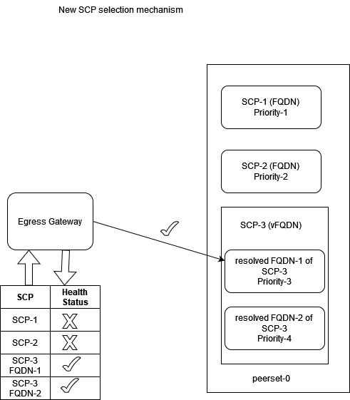
Once peerconfiguration, peersetconfiguration, routesconfiguration,
and peermonitoringconfiguration parameters are configured at Egress Gateway
microservice, and all SCPs (after Alternate Route Service (ARS) resolution, if any vFQDN
is configured) are marked initially as healthy. The peers attached to the associated
peerset are scheduled to run health API checks and update the health status
continuously.
peermonitoringconfiguration is set to false by default. Since, this
feature is an add-on to the existing SBI Routing feature and will be activated if the
sbirouteconfig feature is enabled. To enable this feature, perform
the following:
- configure
peerconfigurationwithhealthApiPath - configure
peersetconfiguration - configure
sbiroutingerroractionsets - configure
sbiroutingerroractionsets - configure
routesconfiguration - enable
peermonitoring
If SBI Routing feature is enabled before upgrading, the
healthApi in peerconfiguration should be attached
manually to existing configured peers. If the operator tries to enable
peermonitoringconfiguration and the targeted peers do not have the
healthApiPath then an appropriate error response is sent.
Managing Monitoring the Availability of SCP Using SCP Health APIs
This section explains the procedure to enable and configure the feature.
Configure
You can configure the Monitoring the Availability of SCP using the REST API.
- create or update peer
Peer Configurationwith health status endpoint details. - create or update the peerset
peersetconfigurationto assign these peers - enable the feature using the below peermonitoring configuration
peermonitoringconfiguration.
Note:
Health Monitoring of the peer will start only after the feature is enabled and the corresponding peerset is used insbirouteconfig.
Observe
- oc_egressgateway_peer_health_status
- oc_egressgateway_peer_health_ping_request_total
- oc_egressgateway_peer_health_ping_response_total
- oc_egressgateway_peer_health_status_transitions_total
- oc_egressgateway_peer_count
- oc_egressgateway_peer_available_count
Alert
3.19 Supports 3gpp-Sbi-Correlation-Info Header
The 3gpp-Sbi-Correlation-Info header may be used to contain correlation information such as UE identity, that may be used by an operator in various offline network management, performance analysis and troubleshooting tools/applications to identify messages (requests, responses, subscriptions, notifications) related to a particular subscriber.
By supporting this feature, BSF as a service consumer or as a service producer generates, forwards and sends the UE identity in 3gpp-Sbi-Correlation-Info header, to identify the UE related to the HTTP request or response.
- BSF receives the correlation-info header and forwards them to the producer NFs.
- BSF does not receive the correlation-info header, then BSF generates and forwards them to the producer NFs.
In BSF, generation of new correlation-info header is managed by the NF Communication Profile configuration page. This allows enable or disable of header generation along with the flexibility of selecting correlation type to use for the header. The correlation-types such as SUPI, GPSI, or both are supported for this release.
The generated or received headers can only be forwarded when the setting Send Correlation-Info Header as part of NF Communication Profile is enabled. NF Communication Profile must be attached to PCF Communication Profile under the Audit section of the Management Service page
3gpp-Sbi-Correlation-Info
Note:
- The possibility to include more than 1 correlationinfo
parameter in the 3gpp-Sbi-Correlation-Info header is kept for future
extensibility.
correlationinfo = ctype "-" cvalue
ctype = "imsi" / "impi" / "suci" / "nai" / "gci" / "gli" / "impu" / "msisdn" / "extid" / "imei" / "imeisv" / "mac" / "eui" / token
- The token is defined for future extensibility.
The token of ctype shall not use the dash ("-") character.
cvalue = 1*tchar
Table 3-18 The format of cvalue shall comply with the data type description.
| ctype | Description |
|---|---|
| SUPI | VarUeId format defined for IMSI and starting after the string "imsi-" |
| GPSI | VarUeId format defined for MSISDN and starting after the string "msisdn-" |
Table 3-19 3GPP defined Custom HTTP Headers
| Header | Description | Example |
|---|---|---|
| 3gpp-sbi-correlation-info | This header may be used to contain correlation information such as UE identity, that may be used by an operator in various offline network management, performance analysis and troubleshooting tools/applications to identify messages (requests, responses, subscriptions, notifications) related to a particular subscriber. |
EXAMPLE 1: When UE identifier used is SUPI and SUPI type is an IMSI: 3gpp-Sbi-Correlation-Info: imsi-345012123123123 EXAMPLE 2: When UE identifier used is GPSI and GPSI type is an MSISDN:3gpp-Sbi-Correlation-Info: msisdn-1234567890 EXAMPLE 3: When UE identifiers used are SUPI and GPSI where SUPI type is an IMSI and GPSI type is an MSISDN:3gpp-Sbi-Correlation-Info: imsi-345012123123123; msisdn-1234567890 |
Managing SBI messages correlation using Subscriber Identity
This section explains the procedure to enable and configure the feature.
Configure
In CNC Console, enable this feature in the NF Communication Profile page.
For more details on enabling or disabling the correlation-info header on GUI, see Service Configurations.
Configure Using REST API
For configuring parameters for SBI messages correlation using Subscriber Identity feature using REST APIs, see Oracle Communications Cloud Native Core, Binding Support Function REST API Specification Guide.
Observe
- ocbsf_correlation_info_header_received
- ocbsf_correlation_info_header_forwarded
- ocbsf_correlation_info_header_generated
3.20 Configurations for Pre and Post Upgrade/Install Validations
This feature applies validation checks that are required on the application, databases, and its related tables before and after the upgrade/installation of BSF application.
On enabling this mandatory pre-flight and post-flight validation checks, for successful upgrade/installation following are validated:
- does the related database exists
- does all the required tables exist
- does the required table schema exist for all the required tables
- does all the required infrastructure exists
This pre-flight and post-flight checks ensures that all the dependent databases, tables, schema, applications are in right order for performing successful update/installation.
For more information on how to how to set the parameter value for pre and post flight checks, see Upgrade Hardening, Pre and Post Flight Checks section in Oracle Communications Cloud Native core, Binding Support Function (BSF) Installation, Upgrade and Fault Recovery Guide.
3.21 Detection and Handling of Late Arrival Requests
BSF receives requests from Ingress Gateway with the 3GPP headers. These requests help in detecting the response time for the BSF Management Service. The Ingress Gateway receives the following headers:
- 3gpp-Sbi-Origination-Timestamp- It contains the timestamp when the originating entity initiates the request
- 3gpp-Sbi-Max-Rsp-Time- The header indicates the duration (expressed in milliseconds) during which the HTTP client waits for a response.
If the configuration for determining the late arriving requests is enabled and BSF does not receive the required headers, the requests are valid and processed. The call flow will continue as normal.
BSF must be able to read the 3gpp-Sbi-Origination-Timestamp and 3gpp-Sbi-Max-Rsp-Time headers to respond to the request. Consider the following scenarios:
- If the sum of 3gpp-Sbi-Origination-Timestamp and 3gpp-Sbi-Max-Rsp-Time is less than the current time, the PCF service rejects the message with a 504 HTTP code and sends the message "TIMED_OUT_REQUEST".
- If the request does not include either 3gpp-Sbi-Origination-Timestamp or 3gpp-Sbi-Sender-Timestamp, or 3gpp-Sbi-Max-Rsp-Time headers, then the request is accepted. There are no changes in the call flow with the inclusion of collision detection.
- If 3gpp-Sbi-Max-Rsp-Time receives a negative value, the header is considered invalid. In this case, the service fallbacks to the default behavior and accepts the request irrespective of the 3gpp-Sbi-Origination-Timestamp or 3gpp-Sbi-Sender-Timestamp value.
Figure 3-22 Request Timeout in BSF
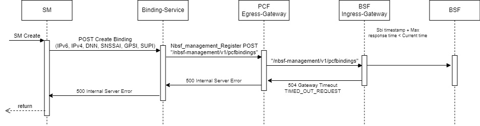
For handling and detection of Late Arrival and Collision Detection functionality in BSF, it is necessary that these headers and the new Custom header are transmitted from PCF to BSF.
Custom Header Enhancement adds the Time Stamp as a default value in the request and response custom headers with specific time formats and time zones. A valid function definition for timestamp in the configuration is: func: currentTime(time-format,time-zone).
Note: Here, only the GMT, IST, PST, and UTC time zones are to be considered for all 5G timestamps.
The only date format supported for the headers is RFC 7231: EEE, dd MMM yyyy HH:mm:ss.SSS zzz (Sun, 04 Aug 2019 08:49:37.845 GMT).
Any other format will result in a parse error which leads to not using the header for the feature (taking it as null value).
Collision Detection
BSF may encounter a colliding or duplicate request for a binding registration from a different PCF. BSF shall consider a request as colliding or duplicate binding registration when two registrations are for the same subscriber (SUPI), DNN, SNSSAI, IPV4/IPv6 prefix, or IpDomain (in case IPv4Address is present) but from different PCF instances (ID/pcfDiamHost/pcfFqdn or pcfIpEndPoints).
In case support for timer headers is enabled:
- If 3gpp-Sbi-Origination-Timestamp header support is enabled and the colliding or the duplicate requests contain the header with an appropriate value, compare the values. If the values are different, it will consider the request with the more recent timestamp in the header.
- If the value of 3gpp-Sbi-Origination-Timestamp in both the requests is the same, then if Custom-Sbi-Sender-Timestamp header support is enabled and the colliding or the duplicate requests contain the header with an appropriate value, compare the values. It will consider the request with the more recent timestamp in the header.
In case support for timer headers is disabled:
- If 3gpp-Sbi-Sender-Timestamp header support is enabled and the colliding or the duplicate requests contain the header with an appropriate value, compare the values. If the values are different, it will consider the request with the more recent timestamp in the header.
- If the value of 3gpp-Sbi-Sender-Timestamp in both requests is the same, it will consider the later request.
If the incoming colliding or duplicate request has an older timestamp than the ongoing or existing request or record, it will reject the request with an HTTP "403 Forbidden" status code. The condition name for the error in the GUI is "Existing binding information found in DB" on the SBI Error Codes configuration page. The BSF function to detect and resolve collision requests is configurable.
If Late Arrival functionality is not enabled, the headers must be propagated to bsf-management-service if collision detection is required or enabled. For this, Ingress Gateway should populate three new collision headers following the required criteria:
Table 3-20 Collision Headers
| At Ingress Gateway | At bsf-management-service |
|---|---|
| 3gpp-Sbi-Origination-Timestamp | collision-3gpp-origination-timestamp |
| Custom-Sbi-Sender-Timestamp | collision-custom-sender-timestamp |
| 3gpp-Sbi-Sender-Timestamp | collision-3gpp-sender-timestamp |
Note:
These collision headers implement collision detection at BSF.You can enable or disable the collision detection in the General Settings of the General Configuration window of the CNC Console.
Figure 3-23 Enabling Collision Detection
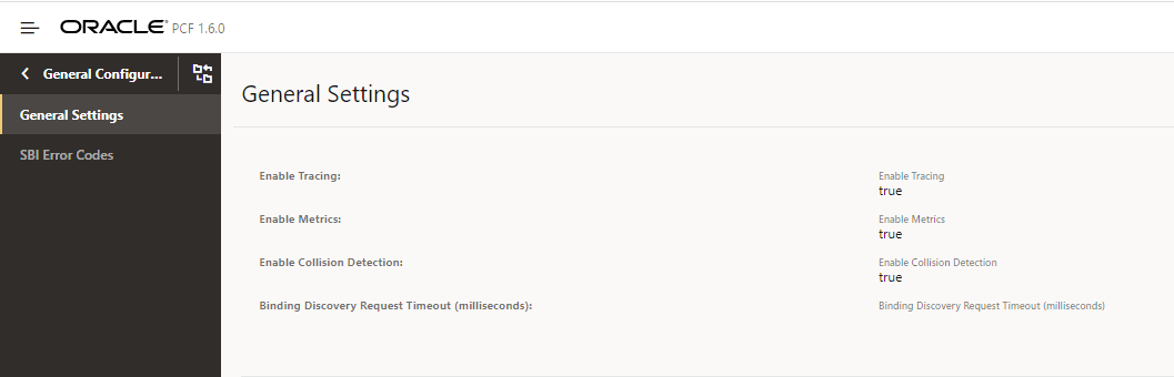
You can enable or disable the collision detection feature using the REST API for BSF. Use the General Settings REST API to enable or disable this feature.
REST API Path: /oc-bsf-configuration/v1/general
For more information, see the Oracle Communications Cloud Native Core Binding Support Function User Guide.
Configuration
routesConfig:
    - id: bsf_management_register
      uri: http://{{ template "service-name-bsf-management" . }}:{{ .Values.global.servicePorts.bsfManagementServiceHttp }}
      path: /nbsf-management/**
      order: 1
      method: POST
      filters:
        customReqHeaderEntryFilter:
          headers:
            - methods:
              - POST
              headersList:
                - headerName: 3gpp-Sbi-Message-Priority
                  defaultVal: 24
                  source: incomingReq
                  sourceHeader: 3gpp-Sbi-Message-Priority
                  override: false
                - headerName: collision-3gpp-origination-timestamp
                  source: incomingReq
                  sourceHeader: 3gpp-Sbi-Origination-Timestamp
                  override: false
                - headerName: collision-custom-sender-timestamp
                  source: incomingReq
                  sourceHeader: Custom-Sbi-Sender-Timestamp
                  override: false

               - headerName: collision-3gpp-sender-timestamp
                  source: incomingReq
                  sourceHeader: 3gpp-Sbi-Sender-Timestamp
                  override: false
Observe
To observe the collision detection functionality, you can use metrics that are specific to BSF management service. For information, see BSF Metrics.
3.22 Support for Timer Configuration
BSF supports the configuration of Diameter interfaces or Rx interfaces timers for all the applicable Diameter messages. The timer configuration needs to be configured for AAR, RAR, STR, and ASR messages. The timer configuration is an option to configure the diameter response timeout value for diameter messages. If the timer value is not configured, then the BSF Diameter gateway works with the default value of 4000 milliseconds for AAR, RAR, STR, and ASR messages.
The Diameter response timeout or the timer value is configured per Diameter interface level. This value can also be configured per message level of the Diameter interface. The timer configuration needs to be configured for Authentication Request (AAR), Re-Auth-Request (RAR), Session-Termination-Request (STR), and Abort-Session-Request (ASR) messages.
For BSF, currently Diameter Rx interface is applicable. The response timeout value is configured using the Rx application level and its messages (AAR, RAR, STR, and ASR) level.
Enable
The timer configuration is a functionality supported by Binding Support Function configurations. You do not need to enable or disable this feature.
Configure
Figure 3-24 General Settings
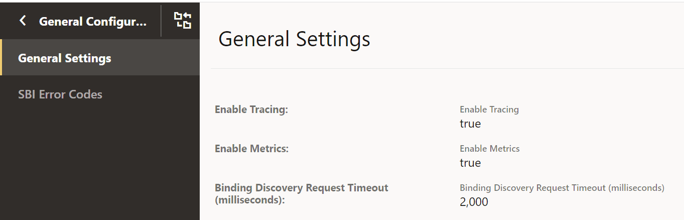
Figure 3-25 Enhanced Timer Configuration
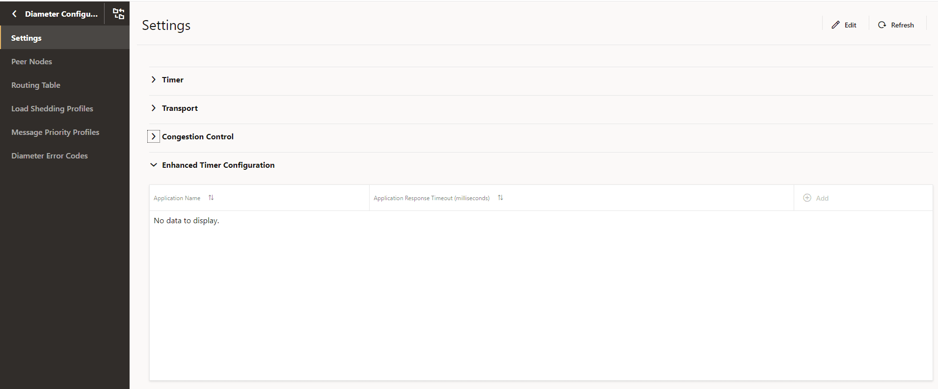
This configuration accepts interface level Diameter response timeout value. If the Diameter interface level timeout is configured, then the user is able to configure message level response timeout value for the corresponding Diameter interface.The response timeout value range for interface and message level is 3000 milliseconds to 2147483647 milliseconds.
Figure 3-26 Edit Enhanced Timer Configuration
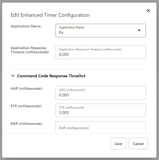
- Configure using CNC Console: Perform the feature configurations on the General Configurations and Diameter Configurations page. For more information about the configurations, see General Settings and Diameter Configurations.
- Configure using REST API: Perform the configurations using GET and PUT operations. For more information about REST API configuration, see Oracle Communications Cloud Native Core, Binding Support Function REST Specification Document.
Observe
To observe the timer configuration functionality, you can use metrics that are specific to BSF management service. For information, see BSF Metrics.
3.23 Support for Session Retry and Alternate Route Service
In previous releases, Binding Support Function was configured with primary and secondary Network Repository Function (NRF) statically and limiting to a specific number. Starting with Release 1.8.0 of BSF, session retry enables the alternate recovery mechanisms to mitigate the impact of any unavailable resource.
This feature allows you to configure virtual FQDNs and perform DNS SRV Lookup to retrieve alternate failover NRF which can be maintained dynamically at the DNS Server.
Managing Session Retry and Alternate Route Service
To enable the Session Retry and Alternate Routing functionality, set the value of enableVirtualNrfResolution to true in the custom-values.yaml file for BSF. For more information on setting the parameter value, see section "Configuring NRF Client" in Oracle Communications Cloud Native Binding Support Function Installation Guide.
- To configure the retry functionality, see "Configuring NRF Client" in Oracle Communications Cloud Native Binding Support Function Installation Guide.
- To configure alternate routing, see section "Alternate Route Service Configuration" in Oracle Communications Cloud Native Binding Support Function Installation Guide.
3.24 XFCC Header Validation
Overview
With XFCC Header Validation feature, Binding Support Function (BSF) as a producer, checks if the SCP that is sending the HTTP request is the same SCP that is configured in the BSF. BSF performs this check by comparing the FQDN of the SCP present in the “x-forwarded-client-cert” (XFCC) of http2 header with the list of FQDN of the SCPs configured in the PCF. This configured list contains all the host FQDNs resolved successfully via DNS-SRV as well as static SCPs. The header validation can be enabled at global as well as at the route level.
Note:
This feature is applicable only when SCP is deployed in the network topology.Configuring SCPs at BSF
To configure SCP, you need to customize custom.yaml
at the time of deploying BSF.
xfccHeaderValidation:
    validation:

      enabled: false
      nfList:
        - scp.com
        - smf.com
        - amf.com
global:
    xfccHeaderValidation:
      validation:
        enabled: false
        peerList:
          - name: scp.com
          - name: smf.com
          - name: amf.com
          - name: scp1.com
            enabled: true
          - name: scp2.com
          - name: scp3.com
            enabled: false
          - name: xyz.test.com
            enabled: true
            scheme: http
            type: virtual
          - name: abc.test.com
            enabled: true
            scheme: https
            type: virtual
          - name: xfcc.test.com
            enabled: false
            scheme: http
            type: virtual
Static SCP: To define an SCP instance statically, add the name and set enabled parameter to true in the peerList. If the enabled parameter is set to false for an instance, then it is not included in the list of configured FQDNs. If you do not specify enabled parameter then by default it is considered as true.
Virtual SCP: To define an SCP with virtual FQDN, add the name, scheme as http or https, type as virtual, and set enabled parameter to true. If the enabled parameter is set to false for an instance, then it is not included in the list of configured FQDNs.
Resolving FQDNs to find Authorized SCPs
dnsSrv:
    port: *svcAlternateRouteServiceHttp #Alternate-route port for scheme 'http'. Change is required if the scheme below changes.
    scheme: http
If Alternate Route service is unable to resolve the configured virtual host, Ingress Gateway stores it in the list of failed FQDNs and reattempts the request at 300 s (default value configured for dnsResolutionInterval).
oc_ingressgateway_dns_resolution: This metric is pegged when DNS resolution for a given FQDN fails.oc_ingressgateway_dns_resolution_failure: This is a gauge metric that is triggered when DNS resolution for a given FQDN fails.
Handling Traffic Flow
- a single XFCC header present in the incoming request to IGW
- multiple XFCC headers are present in the incoming request to IGW
The following figure describes the call flow for validation of a single XFCC header:
Figure 3-27 Call Flow Validation of Single XFCC Header
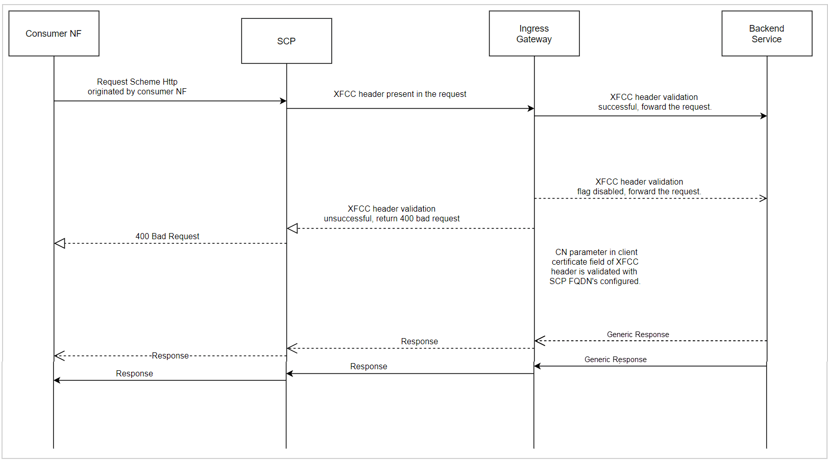
Table 3-21 Single XFCC Header Configuration
| Scenario | Condition | Action |
|---|---|---|
| Ensure that the XFCC Header validation parameter is enabled for the corresponding route match and the matchCerts count is configured correctly.Given XFCC Header validation parameter is enabled for the corresponding route match and matchCerts count correctly configured. | When the matchField parameter of the client certificate field in XFCC header matches with one of the configured NF FQDNs . | Forwards the request to a back-end microservice and receives a corresponding response. |
| Given XFCC header validation parameter is enabled for the corresponding route match and matchCerts count correctly configured. | When matchField parameter of client certificate field in XFCC header does not match with the configured NF FQDNs. | Return a 400 Bad Request response from
Ingress Gateway.
For more information about error codes, see SBI Error Codes Configurations |
| Given XFCC header validation parameter disabled for the corresponding route match. | NA | Forwards the request to the back-end microservice and receives a corresponding response. |
Example of a single XFCC header request:
 x-forwarded-client-cert:
                    By=http://router1.blr.com;Hash=468ed33be74eee6556d90c0149c1309e9ba61d6425303443c0748a02dd8de68;
                    Subject="/C=US/ST=CA/L=San Francisco/OU=Lyft/CN=Test Client";
                    URI=http://testenv1.blr.com;DNS=blr.com; DNS=www.blr.com
Figure 3-28 Call Flow Validation of Multiple XFCC Headers
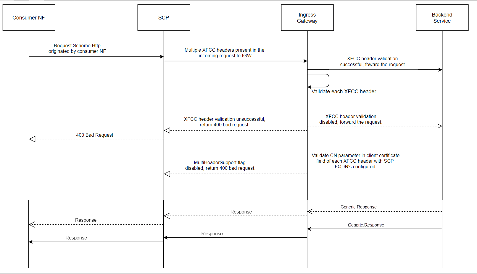
Table 3-22 Multiple XFCC Headers Configuration
| Scenario | Condition | Action |
|---|---|---|
| Given XFCC header validation parameter is enabled and matchCerts count correctly configured to validate across XFCC header certificates from the right most entry. | When matchField parameter of the corresponding client certificate field being validated against currently in the corresponding XFCC header matches with the NF FQDN's configured at Ingress Gateway. | Consider the request as a valid request and forward the request to the back-end micro-service and receive a corresponding response. |
| Given XFCC header validation parameter is enabled and matchCerts count correctly configured to validate across XFCC header certificates from the right most entry. | When matchField parameter of client certificate field in corresponding XFCC headers do not match with the NF FQDN's configured at Ingress Gateway for the corresponding matchCerts count. | Consider the request as an invalid request and
return a 400 Bad Request response from IGW.
For more information about error codes, see SBI Error Codes Configurations |
| Given XFCC header validation parameter is enabled and matchCerts count -1. | NA | Consider the request as valid request and match against the corresponding match field in all XFCC headers, if validation successful then forward the request else return 400 BAD Request. |
| Given XFCC header validation parameter is disabled. | NA | Forward the request to back-end microservice and receive a corresponding response. |
Example of multiple XFCC header request:
x-forwarded-client-cert:By=http://router1.blr.com;Hash=468ed33be74eee6556d90c0149c1309e9ba61d6425303443c0748a02dd8de68;
                        Subject="/C=US/ST=CA/L=San Francisco/OU=Lyft/CN=nf1.com";
                        URI=http://testenv1.blr.com; DNS=nf8.com; DNS=nf1.com; DNS=nf6.com,
                        By=http://router1.blr.com;Hash=468ed33be74eee6556d90c0149c1309e9ba61d6425303443c0748a02dd8de68;
                        Subject="/C=US/ST=CA/L=San Francisco/OU=Lyft/CN=nf10.com";
                        URI=http://testenv1.blr.com; DNS=nf10.com; DNS=nf8.com; DNS=nf9.com,
                        By=http://routexr1.blr.com;Hash=468ed33be74eee6556d90c0149c1309e9ba61d6425303443c0748a02dd8de68;
                        Subject="/C=US/ST=CA/L=San Francisco/OU=Lyft/CN=nf4.com";
                        URI=http://testenv1.blr.com; DNS=nf9.com;
                    DNS=nf4.com;DNS=nf1.com
Managing XFCC Header Validation
- Global Level: To enable or disable the XFCC header validation feature, set the value of the ingress-gateway.global.xfccHeaderValidation.validation.enabled to true or false respectively.
- Route Level: To enable or disable the XFCC header validation
feature at route level, set the value of the xfccHeaderValidation.validationEnabled under routesConfig to
true or false respectively.
Note:
If the xfccHeaderValidation.validationEnabled parameter is defined at route level, then the configuration takes precedence over global configuration.For instance, if you want to enable XFCC header validation for selected routes, then set the global parameter as false and make route specific configuration to true.global: xfccHeaderValidation: validation: enabled: falseroutesConfig: - id: reverse_bsf_service uri: http://{{ template "service-prefix" . }}-bsf-management:{{ .Values.global.servicePorts.bsfManagementServiceHttp }} path: /nbsf-management/** order: 1 metadata: xfccHeaderValidation: validationEnabled: true
For more information about setting the parameter values, see section "XFCC Header Validation Configuration" in Oracle Communications Cloud Native Binding Support Function Installation Guide.
Configure
You can configure the parameter for XFCC Header Validation by updating the custom-values.yaml file for BSF. For more information about configuring the parameter value, see the "XFCC Header Validation Configuration" section in Oracle Communications Cloud Native Binding Support Function Installation Guide.
Observe
To observe the XFCC header validation functionality, you can use metrics that are specific to Ingress Gateway. For information, see Ingress Gateway Metrics.
Configuring Error Codes
errorTrigger:
          - exceptionType: XFCC_HEADER_INVALID
            errorCode: '401'
            errorCause: xfcc header is invalid
            errorTitle: 'Invalid XFCC Header'
            errorDescription: 'Invalid XFCC Header'
          - exceptionType: XFCC_MATCHCERTCOUNT_GREATER_THAN_CERTS_IN_HEADER
            errorCode: '402'
            errorCause: matchCerts count is greater than the certs in the request
            errorTitle: ''
            errorDescription: ''
          - exceptionType: XFCC_HEADER_NOT_PRESENT_OR_EMPTY
            errorCode: '403'
            errorCause: xfcc header is not present or empty in the request
            errorTitle: ''
            errorDescription: ''
If the configured error code in the errorCodeOnValidationFailure field lies in 3xx error series only then the values for retryAfter and redirectUrl if configured under XFCC Header Validation Configuration at Ingress Gateway are used to populate Retry-After and LOCATION headers correspondingly while sending error response from Ingress Gateway.
3.25 Georedundancy Support
The Cloud Native Core (CNC) architecture supports Geographically Redundant (Georedundant) BSF deployments to ensure high availability and redundancy. It offers two, three, or four sites georedundancy to ensure service availability when one of the BSF sites is down.
- All the georedundant sites must have Helm and REST based configurations except for NF InstanceId, BSF Endpoint, and port.
- The georedundant BSF sites must be reachable from NFs or Peers on all the sites.
- The same NFs or Peers must not communicate to other georedundant BSF sites simultaneously for the same session.
- All the sites must register with NRF independently and work in an active state.
- All BSF instances share the Session State data by using the DB Tier replication service. This enables service continuity during the failure of any of the sites.
- The NFs in a given site can discover BSF instances through NRF. However, local configurations such as DNS SRV or static configuration are required to determine the primary and secondary or alternate BSF configuration. When the primary instance is available, the NFs send service requests to the primary instance.
- NRF always reflects current functional status of a given BSF instance. Thus, during the failure of a given BSF instance, the value of NfStatus is updated to SUSPENDED by either NRF or BSF instance. Therefore, when NF detects failure of primary instance due to error response or status notification from NRF, the NF redirects its traffic to the secondary instance, until the primary instance becomes available again.
BSF supports the following types of georedundant deployment:
Two-Site Georedundancy Deployment
The following diagram depicts the topology for two-site georedundant BSF deployment:
Figure 3-29 Two-Site Georedundancy
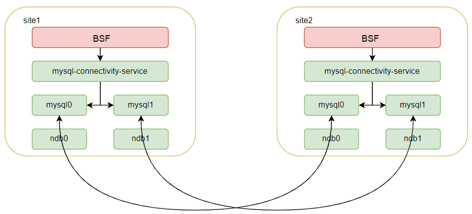
After the second site instance of the cnDBTier is created, you can establish the two site georedundant connections that provide bi-directional data replication between both sites. Therefore, when the records are updated at one site, these changes are replicated to the other remote site in real-time. These updates can be creating, changing, or deleting a record.
Three-Site Georedundancy Deployment
The following diagram depicts the topology for three site georedundant BSF deployment:
Figure 3-30 Three-Site Georedundancy
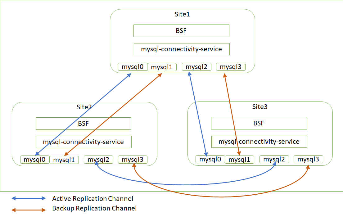
In case of three site georedundancy, bi-directional replication is established from each site to the other two sites. The database updates from each site are replicated to the other two sites over the replication channel.
- The service remains available even when 2 sites become unavailable.
- In case of a single site failure, the remaining two sites keep establishing the bi-directional replication.
- No action is required in case of a site failure.
- Requires 4 SQL pods and 2 rep-svc pods at each site
Four-Site Georedundancy Deployment
The following diagram depicts the topology for four-site georedundant BSF deployment:
Figure 3-31 Four-Site Georedundancy Deployment
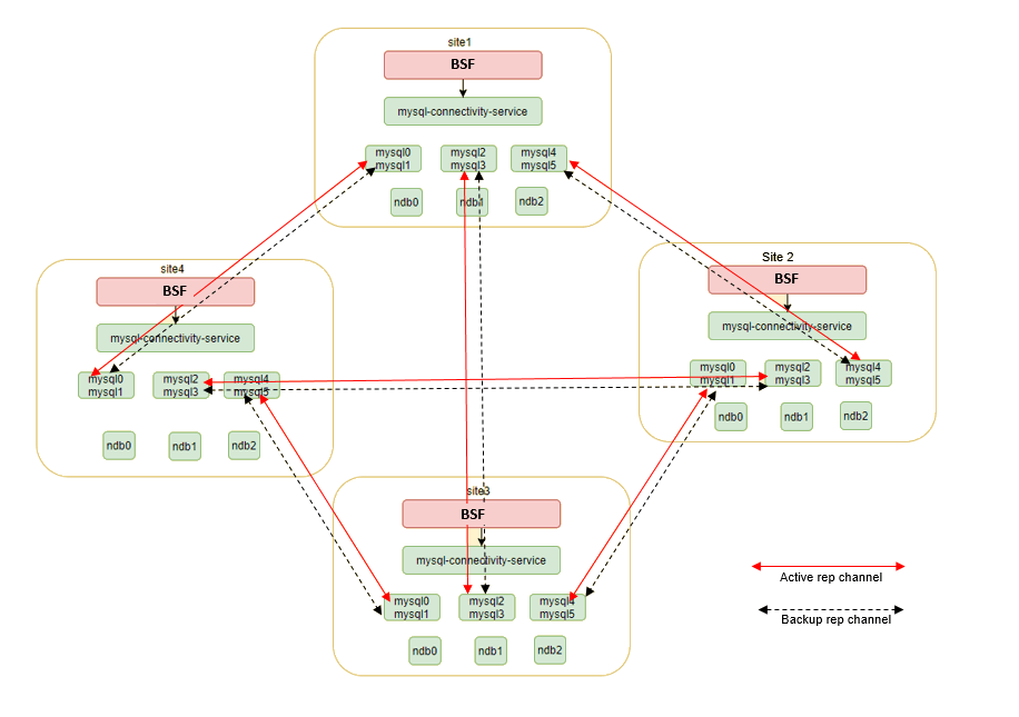
cnDBTier supports the four-site georedundancy deployment. In case of four-site georedundancy, each site participates in a 4-way replication. The database updates from each site are replicated to the other three-sites over the replication channels.
- In case of a single site failure, the remaining three-sites keep establishing the bi-directional replication.
- No action is required in case of a site failure.
- Requires 6 SQL pods and 3 db-rep-svc at each site.
- Each site uses two SQL nodes for active and standby replication channels for high availability of the replication channels.
Managing Georedundancy
Deploy
- Set up the replicated cnDBTier version 1.8.0.0.3 or above on two or three sites as required. For more information about installing cnDBTier, see "Installing cnDBTier" in Oracle Communications cnDBTier Installation Guide.
- Deploy BSF over the replicated (two or three) cnDBTier sites. For more information about installing and deploying BSF, see Oracle Communications Cloud Native Binding Support Function Installation Guide.
Configure
To configure georedundancy:
You need to configure the georedundancy functionality while deploying the BSF instances on the replicated sites. The following parameters must be updated in the custom-values.yaml file for BSF:
Table 3-23 Georedundancy Parameters
| Parameter | Description |
|---|---|
| global.envMysqlHost | The database instance for each site. BSF communicates to the database at the same site only. |
| global.nfInstanceId | The ID for the site |
| config-server.envMysqlDatabase | The database for the config server. The two sites must use different database names for config server |
| cm-service.envCommonConfigMysqlDatabase | The common configuration database. It must be different on the sites |
| nrf-client.configmapApplicationConfig.profile | Configuration data for nrf client. The appProfile and the nfInstanceId parameters must be aligned with global.nfInstanceId |
| nrf-client-nfdiscovery.dbConfig.dbName | The common configuration database. It must be different on the sites |
| nrf-client-nfmanagement.dbConfig.dbName | The common configuration database. It must be different on the sites |
| appinfo.dbConfig.dbName | The common configuration database. It must be different on the sites |
| perf-info.dbConfig.dbName | The common configuration database. It must be different on the sites |
| BSFds.envMysqlDatabaseConfigServer | The database for the config server. The two sites must use different database names for config server |
| ingress-gateway.dbConfig.dbName | The common configuration database for ingress gateway. It must be different on the sites |
| egress-gateway.dbConfig.dbName | The common configuration database for egress gateway. It must be different on the sites |
| alternate-route.dbConfig.dbName | The common configuration database for alternate route. It must be different on the sites |
For more information about configuring the parameter value, see the "Alternate Route Service Configuration" section in Oracle Communications Cloud Native Binding Support Function Installation Guide.
cnDBTier generates critical alerts in case of application or database failure. For more information, see Oracle Communications Cloud Native Core DBTier User Guide.
BSF allows you to monitor the georedundancy deployment through cnDBTier alerts. Access the Prometheus GUI to check for new App alerts.
3.26 Diameter Gateway Pod Congestion Control
The Diameter Gateway is a diameter proxy agent for Binding Support Function (BSF). It is a front-end microservice for diameter traffic for both Ingress and Egress traffic and can get congested due to higher traffic, higher CPU usage, and higher memory utilization. Thus, it is imperative to have suitable congestion control features in place for Diameter Gateway pods to avoid adverse impacts on latency and performance.
Another reason for the need for a congestion control mechanism for Diameter Gateway is the nature of diameter connections. An external LoadBalancer distributes these long-lived connections. As shown in the following image, when the LoadBalancer routes an incoming request from network to Diameter Gateway pod (indicated by green line), the balancer does not take health or load of the pod into consideration. As a result, uneven distribution of traffic can happen, and gateway pods experience congestion.
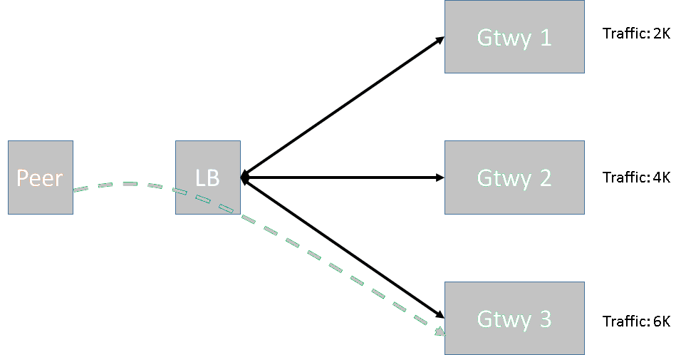
Congestion control helps to identify such conditions and invoke load shedding rules to address these situations when these load conditions persist. With Diameter Gateway service supporting the congestion control mechanism feature, it helps to protects its pods from congestion and ensures consistent service availability to its consumer.
- Determine the pod congestion state
- Trigger Congestion Control
Determining Pod Congestion State
- Normal
- Danger of Congestion (DOC)
- CONGESTION_L1
- CONGESTION_L2
- CONGESTED
Figure 3-32 Different Pod Congestion States

- CPU: The CPU usage for congestion state is calculated by comparing the CPU usage of the container (monitored using cgroup parameter, cpuacct.usage, which provides current cpu usage in nanoseconds) with the configured threshold.
- Queue: For the DOC, CONGESTION_L1, CONGESTION_L2, and CONGESTED pod states, compare the number of pending messages in the queue with the configured pending messages threshold.
stateChangeSampleCount: This REST API parameter can be configured to specify after how many continuous intervals, the pod state can be changed. The default value is 5. This value can range from 1 to 2147483647.stateCalculationInterval: This REST API parameter can be configured to specify the time duration or interval, after which the pod congestion state will be re-verified. The default value is 200ms. This interval is configured in milliseconds and can range from 50 to 2147483647.
For more information about these congestion control configurations, see Congestion Control Settings section in CNC Console.
CPU and Queue Threshold
Table 3-24 Diameter Gateway service Congestion States
| Congestion States | CPU Count | Queue (Pending Request) |
|---|---|---|
| DANGER_OF_CONGESTION (DOC) | 60 | 6300 |
| CONGESTION_L1 | 70 | 7200 |
| CONGESTION_L2 | 75 | 8100 |
| CONGESTED | 80 | 9000 |
For more information about these CPU and Queue count thresholds configurations, see Congestion Control Thresholds section in CNC Console.
Triggering Congestion Control
With Congestion Control feature enabled, every time a message is fetched
for processing, the system checks the current congestion state of the pod. If the
current state is either in DOC, CONGESTION_L1,
CONGESTION_L2, or Congested state, then the
congestion control mechanism is triggered. After verifying that the message type is
a request, a request priority is assigned to it. If the request priority is greater
than or equal to the discard priority, then the message is rejected, otherwise it is
accepted.
Congestion Control Load Shedding using Discard and Request Priority
- Priority
- Priority and Percentage
Table 3-25 Priority based Message Discards
| Congestion State | Discard Priority |
|---|---|
| DANGER_OF_CONGESTION | 27 |
| CONGESTION_L1 | 19 |
| CONGESTION_L2 | 17 |
| CONGESTED | 15 |
Table 3-26 Priority and Percentage based Discards
| Congestion State | Discard Priority Range | Discard Percentage |
|---|---|---|
| DANGER_OF_CONGESTION | 27-31 | 50 |
| CONGESTION_L1 |
19-26 27-31 |
50 75 |
| CONGESTION_L2 |
17-18 19-26 27-31 |
50 75 100 |
| CONGESTED | 15-31 | 100 |
For more information about these Priority or Priority and
Percentage discards configurations, see Congestion Control Load Shedding Rules page in CNC Console.
Table 3-27 Pre-Defined AVP Conditions
| Pre-Defined AVP Conditions | Type Operator | Values |
|---|---|---|
| DRMP |
|
The Diameter Routing Message Priority (DRMP) AVP allows Diameter Gateway to indicate the priority of diameter messages. This will take numeric values. Allowed numeric value in the range of 0-15. |
| OC-Message-Priority |
|
The header attribute allows Diameter Gateway to indicate the priority of diameter messages. This will take numeric values. Allowed numeric value in the range of 0-31. |
In the Message Priority Profiles for Diameter Gateway, if both
DRMP Priority and OC-Message-Priority is
selected, then OC-Message-Priority shall be considered as highest
priority for message priority rule selection. The message priority range for
OC-Message-Priority is 0-31, and for DRMP AVP it is 0-15.
For more information about configuring message priority profiles, see Message Priority Profiles section in CNC Console.
Congestion Response Code
Table 3-28 Advanced Settings
| Key | Value | Description |
|---|---|---|
| CONGESTION_DIAMETER_RESPONSE_CODE | 3004 |
This is to configure the diameter result code for
the congestion control discards and its value shall be
numerical. The value can be set to either
Default Value: 3004 Examples: CONGESTION_DIAMETER_RESPONSE_CODE=5065 CONGESTION_DIAMETER_RESPONSE_CODE=3004 |
| CONGESTION_DIAMETER_VENDOR_ID | 0 |
This is to configure the diameter vendor id for the congestion control discards and its value shall be numerical. If the value is non-zero, then the CONGESTION_DIAMETER_RESPONSE_CODE shall be considered as the experimental result code. If value is zero or it is not configured, then CONGESTION_DIAMETER_RESPONSE_CODE shall be considered as the normal result code. Examples: CONGESTION_DIAMETER_VENDOR_ID=10415 CONGESTION_DIAMETER_VENDOR_ID=21274 |
If above advance settings keys are not configured, then Diameter Gateway will discard
the messages with default diameter result code 3004
DIAMETER_TOO_BUSY.
For more information about different response codes that can be configured, see Congestion Control Discard Message Response Code section.
Call Flow
Table 3-29 Message Priority Profiles
| Message | Priority |
|---|---|
| Default | 6 |
| Rx RAR | 7 |
| Gx CCR-I | 10 |
| Sy SLR | 11 |
Figure 3-33 Call flow diagram for Diameter Congestion Control
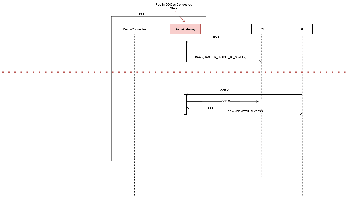
Message will be rejected when message priority is greater than discard priority
- When Diameter Gateway 2, currently is either in DOC or Congested state, receives RAR request, the priority is compared against discard priority. As the message priority is greater than the discard priority, the message is rejected with result code – DIAMETER_UNABLE_TO_COMPLY.
- When Diameter Gateway 2, currently is either in DOC or Congested state, receives AAR-U request, the priority is compared against discard priority. As message priority is higher than discard priority, the message is accepted with result code – DIAMETER_SUCCESS.
Feature Upgrade Impact
With upgrade of BSF application from any of the previous release versions to 25.1.200, the Diameter Gateway pod Congestion Control feature can be updated to use the common Congestion Control mechanism available in 25.1.200. In order to do this, there are some considerations to address, especially due to the difference in configuration data. Diameter Gateway's pod congestion control configurations from the previous version should be migrated to use the current version configurations. The data migration process is manual and one-time activity that user has to perform, by using either the CNC Console or Congestion Control migration APIs.
Feature Transition
Diameter Gateway Congestion Control feature transition between older version to the current version's Congestion Control mechanism is based on migration status of the BSF application during the upgrade. The migration status can be either in "False" or "True".
- Old Configurations: The Diameter Gateway Congestion Control configurations from the previous application version.
- Previous CNC Console pages: User will have access to the older user interface rather than the new screen designed for Congestion Control feature.
- Legacy REST APIs: Calls to APIs will still work with the previous version's endpoints.
True (After Migration): After the upgrade to current BSF version, perform the data migration for Diameter Gateway pod Congestion Control feature. With this, the migration status will be "After Migration" and Diameter Gateway services will be able to use the updated Congestion Control mechanisms.
Managing Diameter Gateway Pod Congestion Control
Enable
By default, the Pod Congestion Control is disabled for Diameter Gateway. You can enable this feature using CNC Console or REST API for BSF.
Feature Migration
If the BSF application is upgraded to the current version, then you can enable this feature by performing the migration process. For more information how to perform the data migration, see "Diameter Gateway Migration of Congestion Control Configurations" section in Settings page using CNC Console.
Configure
- Configure using CNC Console:
To enable the feature using CNC Console, set the Enable parameter in Settings page under Congestion Control for Overload and Congestion Control Configurations for Diameter Gateway Service.
To configure Diameter Gateway service pod congestion control feature in CNC Console, see Congestion Control page in CNC Console.
- Configure using REST API:
To enable this feature using REST API, perform the feature configurations as described in "Congestion Control" APIs section in Oracle Communications Cloud Native Core Binding Support Function REST API Specification Guide.
If the BSF application is upgraded to 25.1.200, then you can enable this feature by performing the migration process. For more information how to perform the data migration using Congestion Control Migration APIs, see "Congestion Migration" APIs section in Oracle Communications Cloud Native Core Binding Support Function REST API Specification Guide.
Observability
- pod_congestion_state
- pod_resource_congestion_state
Note:
Prometheus automatically injects name of the pod name with the label "kubernetes_pod_name" to the metric. This information is further used for alerting purposes.For more information, see the List of Alerts section.
Maintain
Warning logs are generated to indicate the congestion level. Error logs are generated when the system is congested and the actions are needed to be taken to bring the system back to normal. However, no error logs are generated when messages are rejected to avoid additional resource usage to write error logs.
3.26.1 Support for Server Header
BSF handles various requests from consumer Network Functions (NFs) and other network entities over HTTP protocol. On receiving these requests, BSF validates and processes them before responding to these requests. In case, BSF sends an error response, then the consumer NFs need to know the source of the error to trouble shoot the error and take corrective measures. The integration of this feature at BSF helps to determine the originator of the error response.
This feature offers the support for Server Header in BSF responses, which contains information about the origin of an error response and the type of the error encountered. The Server Header includes the type of NF as "NF Type", followed by a “-” and the identity of the NF or the network entity. It is expected to be present in all BSF responses in the following format:
<NF_Type>-<NF_Instance_Id>
<NF Type>is the type of the NF generating the error.<NF Instance-Id>is the unique identifier of the NF instance generating the error response.
For example: BSF-54804518-4191-46b3-955c-ac631f953ed8
The inclusion of the Server header in the BSF response is configurable, and can be enabled or disabled using a flag. Also the error codes that are included as part of the Server header in the error response are also configurable. The configuration of these parameters are done through either with REST APIs that are exposed through configuration server or Helm Configurations.
REST or HELM for
Server Header configuration is done using the below
flag:
ingress-gateway:
  serverHeaderConfigMode: REST # Possible values: HELM, REST. Based on this value, the feature flag for "server"  header will need to be enabled either in Helm configuration or Rest  configuration.
Note:
Nf Type and Nf Instance Id are mandatory fields for Server Header to get included in the error response. If either of the fields Nf Type or Nf Instance Id are configured as empty, then the Server Header will not get included in the error response.Managing Server Header
Enable
By default, this feature is disabled.
- Helm: To enable the server header feature using Helm
configuration, set the value for parameter
serverHeaderConfigModeto HELM in thecustom-values.yamlfile. Then, set the value for parameterserverHeaderDetails.enabledtotrueunder global and routesConfig for ingress-gateway. - REST API:To enable the server header feature using
REST configuration, set the value for parameter
serverHeaderConfigModeto REST in thecustom-values.yamlfile. Using REST API, set theenabledparameter to true in the following resource URI:{apiRoot}/BSF/nf-common-component/v1/igw/serverheaderdetails
Configure
- Configure using REST API:
Perform the REST API configurations in the following sequence to configure this feature:
- Configure serverheaderdetails to enable
the feature.
{apiRoot}/BSF/nf-common-component/v1/igw/serverheaderdetails
- Configure routesconfiguration to map
route ID and its corresponding route-level configuration.
{apiRoot}/BSF/nf-common-component/v1/igw/routesconfiguration
- Configure errorcodeserieslist to update
the errorcodeserieslist that are used to list the
configurable exception or error for an error scenario in
Ingress Gateway.
{apiRoot}/BSF/nf-common-component/v1/{serviceName}/errorcodeserieslist
Note:
If you define server header configuration at both global and route levels, the route level configuration takes precedence over the global level configuration.For more information, see the "Server Header at Ingress Gateway" section in Oracle Communications Cloud Native Core, Binding Support Function REST Specification Guide.
- Configure serverheaderdetails to enable
the feature.
- Configure using Helm: When parameter
serverHeaderConfigModeis set toHELMand to configure the Server Header at Ingress Gateway, you need to perform the helm configurations either at Global or at Route level.Following Helm Configuration performed at Global Level:
# All attributes under "serverHeaderDetails" will need to be configured only if "serverHeaderConfigMode" is set as "HELM"
serverHeaderDetails:
  enabled: true
  errorCodeSeriesId: E1
  configuration:
    nfType: BSF
    nfInstanceId: INS-1

# Use below configuration to define errorCodeSeries list
errorCodeSeriesList:
  # Value of "id" attribute will need to used for assigning "errorCodeSeriesId" either at Global or Route level conf for Server header.
- id: E1
  errorCodeSeries:
  - errorSet: 4xx
    errorCodes:
    - 400
    - 408
  - errorSet: 5xx
    errorCodes:
    - 500
    - 503
- id: E2
  errorCodeSeries:
  - errorSet: 4xx
    errorCodes:
    - -1
Following Helm Configuration performed at Route Level:
routesConfig:
- id: backend_ms1_route
  uri: https://backend-ms1:8440/
  path: /ms1/**
  order: 1
  metadata:
    # All attributes under "serverHeaderDetails" will need to be configured only if "serverHeaderConfigMode" is set as "HELM" and Route level configuration is required. If not defined, Global configurations will be used
    serverHeaderDetails:
      enabled: true     # Since this flag is set to true at Route level, "server" header configuration will be enabled for this Route with respective "errorCodeSeriesId" as E2
      errorCodeSeriesId: E2 # This attribute will need to be defined if "server" header configuration is enabled at Route level.
- id: backend_ms2_route
  uri: https://backend-ms2:8550/
  path: /ms2/**
  order: 2
  metadata:
    # All attributes under "serverHeaderDetails" will need to be configured only if "serverHeaderConfigMode" is set as "HELM" and Route level configuration is required. If not defined, Global configurations will be used
    serverHeaderDetails:
      enabled: false    # Since this flag is set to false at Route level, "server" header configuration will be disabled for this Route altogether.
Note:
If you define server header configuration at both global and route levels, the route level configuration takes precedence over the global level configuration.For more information, see the "Server Header Configurations" section in the Oracle Communications Cloud Native Core, Binding Support Function Installation and Upgrade Guide.
- Configure using CNC Console:This feature can be configured using NF Communication Profile and PCF Communication Profile under the Audit section of the Management Service page.
3.27 Overload Control
Overload means when 100% of the planned capacity is exhausted. It can be due to uneven distribution of traffic towards a given policy service instance, network fluctuations leading to traffic bursts or unexpected high traffic volume at any given point of time.
During overload conditions, the service response times may grow to unacceptable levels, and exhaustion of resources can result in downtime or services exhibiting unexpected behavior. Overload management is a critical requirement for any telecom node, server, and service to protect against downtime and ensure serviceability during extreme overload conditions. Thus, overload management aims to prevent service performance from degrading in an uncontrolled manner under heavy loads. When BSF service starts approaching its saturation or planned limit, response times typically grow high and throughput may degrade substantially. Under such conditions, it is desirable to shed load based on the user's configuration, instead of causing all messages and signaling flows to experience unacceptable response times, failures, or downtime.
BSF allows to configure a percentage of messages to be rejected. That is, messages are discarded based on configured percentage. This enables system's overload and congestion control to manage gauge system's load with better accuracy. Also, it allows the user to provide less rejections instead of providing 100% rejections.
Percentage of message rejections for each load level is configurable. Also, the rejection percentage for each message priority can be configured.
For example, if the discard value for CCR-I messages is 50% , when the system is under load, 50% of the messages are accepted and 50% of them are rejected.
Note:
All CCR-Ts are accepted.
Enable
true in the
custom-values.yaml file for BSF:
- perf-info.overloadManager.enabled
custom-values.yaml
file:perf-info:
envMysqlDatabase: ''
overloadManager:
enabled: false
ingressGatewaySvcName: occnp-ingress-gateway
ingressGatewayPort: *svcIngressGatewayHttp
# nfType is used to query configuration from common cfg server
nfType: BSF
# diam Gateway overload management feature configurations
diamGWPort: *svcDiamGatewayHttpFor more information about setting the parameter values, see Overload Manager Configurations in Oracle Communications Cloud Native Core, Binding Support Function Installation, Upgrade, and Fault Recovery Guide.
Configure
- Configure using REST API: BSF provides
overloadLevelThresholdandoverloadLevelThresholdProfilesAPI end points to configure overload control feature.You can perform the POST, PUT, or GET operations to configure the feature. For more information about REST API configuration, see Overload Level Threshold Overload Level Threshold sections in Oracle Communications Cloud Native Core, Binding Support Function REST API Specification Guide.
- Configure using CNC Console: Using CNC Console, you can configure the threshold values based on profiles. For more information, see Overload Control Threshold.
Recommended Overload Threshold Values - BSF Management Services
This section describes the recommended default overload threshold values for BSF Management Services. To calculate threshold values, you must consider the resource values for microservices. The following table lists the default resource values for BSF Management Services:
Table 3-30 Default Resource Values
| Resources | Values |
|---|---|
| CPU (Limits) | 4 |
| CPU (Requests) | 3 |
| Maximum CPU Usage | 1.6 |
| Maximum CPU Usage (%) | 61 |
| Maximum Replicas | 8 |
| Maximum TPS | 1500 |
| Maximum TPS (all replicas) | 12000 |
| Worst RTT (assumed) | 250 ms |
| Maximum Pending Transactions | 2100 |
Table 3-31 Formulas to Calculate Default Overload Threshold Levels
| Load Level | CPU (%) | Pending Message Count(Absolute Value) | Failure Count(Absolute Value) |
|---|---|---|---|
| L1 - Onset | 80% * C | 60% * P | 05% * T |
| L1 - Abatement | 75% * C | 50% * P | 03% * T |
| L2 - Onset | 90% * C | 75% * P | 10% * T |
| L2 - Abatement | 85% * C | 70% * P | 08% * T |
| L3 - Onset | 95% * C | 90% * P | 15% * T |
| L3 - Abatement | 91% * C | 85% * P | 12% * T |
Abatement value is the lower range where as the onset value is higher range for that particular level.
Note:
C denotes the maximum CPU utilization per pod of core-service
P denotes the maximum pending transaction size value based on worst RTT and max TPS, that is, 25K/s * 2000ms = 50000.
T denotes the maximum TPS of a given service.
Note:
You can configure the memory for each of these services.Note:
These are the recommended values. It can be modified as per the customer requirements.Table 3-32 Default Overload Threshold Values - BSF Management Services
| Load Level | CPU (%) | Pending Message Count | Failure Count |
|---|---|---|---|
| L1 - Onset | 44 | 1260 | 420 |
| L1 - Abatement | 41 | 1050 | 252 |
| L2 - Onset | 49 | 1575 | 840 |
| L2 - Abatement | 47 | 1470 | 672 |
| L3 - Onset | 52 | 1890 | 1260 |
| L3 - Abatement | 50 | 1785 | 1008 |
Observe
- service_resource_stress
- service_resource_overload_level
- load_level
- system_overload_threshold_config_mode
- active_overload_threshold_fetch_failed
Alerts
-
BSF provides the following alerts for overload control feature on SBI interface:
ServiceOverloaded- This alert is raised whenever a given service is in overload state - L1, L2, and L3.ServiceResourceOverLoaded- This alert is raised when a given service is in overload state - L1, L2, or L3 due to resource types such as memory, CPU, pending count, and failure count.
-
BSF provides
PERF_INFO_ACTIVE_OVERLOAD_THRESHOLD_FETCH_FAILEDalert for overload control threshold configuration. This alert is raised when the service is unable to fetch the current active overload threshold data.
Maintain
Error logs are generated when the system is overloaded and the actions taken to bring the system back to normal. Warning logs are generated to indicate the change in load level.
3.27.1 Overload Control - Diameter
- Pre-defined threshold load levels.
- Tracks number of pending and failure messages from Diameter Gateway.
- Tracks CPU and memory usage of Diameter Gateway.
- Enforce load shredding during various overload levels based on priority and percentage discard value for each priority. The priority and percentage discard value are configurable.
Configure
Note:
Currently, threshold values can be configured using REST API only.- Configure using CNC Console: Perform the feature configurations on the Load Shedding Profiles and Message Priority Profiles page. For more information about the configurations, see Load Shedding Profiles.
- Configure using REST API: BSF provides the following REST API for
configuring Overload Control feature on Diameter Gateway:
Load Shedding Profiles: {apiRoot}/oc-bsf-configuration/v1/diameter/loadsheddingprofiles
Message Priority Profiles: {apiRoot}/oc-bsf-configuration/v1/diameter/messagepriorityprofiles
You can perform the POST, PUT, or GET operations to configure the feature. For more information about REST API configuration, see Oracle Communications Cloud Native Core, Binding Support Function REST API Specification Guide.
{
  "name": "default_overload_control_load_shedding_profile",
  "type": "Overload Control",
  "overloadLoadSheddingRules": [{
    "level": "L1",
    "discardPriority": 13,
    "ansWithResultCode": "DIAMETER_TOO_BUSY"
  }, {
    "level": "L2",
    "discardPriority": 11,
    "ansWithResultCode": "DIAMETER_TOO_BUSY"
  }, {
    "level": "L3",
    "discardPriority": 6,
    "ansWithResultCode": "DIAMETER_TOO_BUSY"
  }]
}
{
"name": "default_msg_priority_profile",
"priorityRules": [{
"ruleName": "Rx_AAR_I",
"messagePriority": 13,
"rulePriority": 1,
"enableDRMPPriority": true,
"conditions": {
"application": "Rx",
"message": "AAR",
"preDefinedAVPConditions": [{
"conditionName": "Rx-Request-Type",
"conditionRxRTValue": ["INITIAL_REQUEST"]
}]
}
}, {
"ruleName": "Rx_STR",
"messagePriority": 7,
"rulePriority": 1,
"enableDRMPPriority": true,
"conditions": {
"application": "Rx",
"message": "STR",
"preDefinedAVPConditions": []
}
}, {
"ruleName": "Rx_AAR_U",
"messagePriority": 11,
"rulePriority": 1,
"enableDRMPPriority": true,
"conditions": {
"application": "Rx",
"message": "AAR",
"preDefinedAVPConditions": [{
"conditionName": "Rx-Request-Type",
"conditionRxRTValue": ["UPDATE_REQUEST"]
}]
}
}]
}Observe
- diam_overload_message_reject_total
3.27.2 Overload Control - SBI
- Pre-defined threshold levels
- Tracks number of pending messages for BSF service
- Tracks number of failed responses (configurable as error code) generated BSF service
- Tracks CPU and memory usage of BSF services
- Determines the overload level of the system using data collected from all the above mentioned points against planned threshold levels.
- Enforce load shedding at various overload levels
Configure
Note:
Currently, threshold values can be configured using REST API only.- Configure using CNC Console: Perform the feature configurations on the Discard Policy Mapping, Discard Policy, and Error Code Profiles pages. For more information about the configurations, see Overload and Congestion Control Configurations.
- Configure using REST API: BSF provides the following
REST APIs for configuring overload control feature on SBI interface:
-
OC Policy Mapping: {apiRoot}/BSF/nf-common-component/v1/igw/ocpolicymapping
-
OC Discard Policies: {apiRoot}/BSF/nf-common-component/v1/igw/ocdiscardpolicies
-
Error Code Profiles: {apiRoot}/BSF/nf-common-component/v1/igw/errorcodeprofiles
You can perform the GET, PUT, or PATCH operations to configure the feature. For more information about REST API configuration, see Oracle Communications Cloud Native Core, Binding Support Function REST API Guide.
-
Table 3-33 Default Message Priority Values
| Message Type | Priority |
|---|---|
| bsf_management_register | 24 |
| bsf_management_deregister | 18 |
| bsf_management_discovery | 24 |
3.28 Rate Limiting - SBI
- BSF Management Register - POST method
- BSF Management Deregister - DELETE method
- BSF Management Discovery - GET method
Note:
Ingress Gateway determines the number of messages being dropped or rejected in the current sampling period based on extra unrejected messages received in the previous sampling period.Managing Rate Limiting
Enable
- CNC Console: By default, this feature is disabled. To enable the rate limiting feature using CNC Console, set the Enable Rate Limiting parameter to true on the Rate Limiting Policy page.
-
REST API: By default, this feature is disabled. To enable the rate limiting feature using REST API, set the
enabledparameter to true in the following resource URI:Define rate limit: {apiRoot}/BSF/nf-common-component/v1/igw/routelevelratelimiting
Define rate limit at route level: {apiRoot}/BSF/nf-common-component/v1/igw/routesconfiguration
For more information, see Rate Limiting at Ingress Gateway section in Oracle Communications Cloud Native Core, Binding Support Function REST API Guide.
Configure
- Configure using CNC Console: Perform the feature configurations on the Rate Limiting Policy, Route Level Mapping, and Error Code Profiles pages. For more information about the configurations, see Overload and Congestion Control Configurations.
- Configure using REST API: BSF provides the following
REST API for configuring Overload Control feature on SBI interface:
Define error code profiles: {apiRoot}/BSF/nf-common-component/v1/igw/errorcodeprofiles
Define rate limit: {apiRoot}/BSF/nf-common-component/v1/igw/routelevelratelimiting
Define rate limit at route level: {apiRoot}/BSF/nf-common-component/v1/igw/routesconfiguration
You can perform the GET, PUT, or PATCH operations to configure the feature. For more information about REST API configuration, see Oracle Communications Cloud Native Core, Binding Support Function REST API Specification Guide.
3.29 Pod Protection at Ingress Gateway
This section describes how to protect the Ingress Gateway pods when they are overloaded with numerous incoming requests.
The Ingress Gateway pods are not protected against any incoming traffic congestion. As a result, the pods are overloaded and congested. This impacts system latency and performance. It also leads to stability issues due to uneven distribution of connections and traffic on Ingress Gateway pods. As a front end microservice for HTTP traffic, it is important for Ingress Gateway to have pod protection implemented.
Table 3-34 Configuring Threshold Limit
| Level | Resource |
|---|---|
| DoC |
|
| Congested |
|
Configure
- Configure using REST API: BSF provides the following
REST API:
{apiRoot}/BSF/nf-common-component/v1/igw/podprotection
You can perform the GET, PATCH, or PUT operation to configure the feature. For more information about REST API configuration, see Oracle Communications Binding Support Function REST API Specification Guide.
3.30 Service Mesh for Intra-NF Communication
BSF leverages the Istio or Envoy service mesh (Aspen Service Mesh) for all internal and external communications. The service mesh integration provides inter-NF communication and allows API gateway co-working with service mesh. The service mesh integration supports the services by deploying a sidecar proxy in the environment to intercept all network communications between microservices.
The Aspen Service Mesh (ASM) configurations are classified into:
- Control Plane: It involves adding labels or annotations to inject sidecar.
- Data Plane: It helps in traffic management such as handling NF call flows by adding Service Entries (SE), Destination Rules (DR), Envoy Filters (EF), and other resource changes such as apiVersion change between versions. This is done manually depending on each NF requirement and ASM deployment.
Managing Service mesh for intra-NF Communication
- serviceMeshCheck
- istioSidecarQuitUrl
- istioSidecarReadyUrl
For more information on enabling the parameter value, see "Aspen Service Mesh Configurations" in Cloud Native Binding Support Function Installation and Upgrade Guide.
The Aspen Service Mesh (ASM) configurations are classified into:
- Control Plane: For information on configuring the parameter value, see "Aspen Service Mesh Configurations" section in Oracle Communications Cloud Native Binding Service Function Installation Guide.
- Data Plane: For information about Data plane configurations, see "Aspen Service Mesh Data Plane Configurations" in Cloud Native Binding Support Function Installation and Upgrade Guide.
When ASM is enabled, the ASM sidecar can modify the Server
header in an Audit Notification response received by BSF. To preserve the header
value unchanged, configure an EnvoyFilter with
server_header_transformation: PASS_THROUGH for the BSF
workload.
Use the following EnvoyFilter configuration. Update the
namespace value to the namespace of the target BSF
deployment before applying it:
apiVersion: networking.istio.io/v1alpha3
kind: EnvoyFilter
metadata:
  name: preserve-server-header
  namespace: <BSF_NAMESPACE>
spec:
  workloadSelector:
    labels:
      application: ocbsf
  configPatches:
  - applyTo: NETWORK_FILTER
    match:
      listener:
        filterChain:
          filter:
            name: "envoy.filters.network.http_connection_manager"
    patch:
      operation: MERGE
      value:
        name: "envoy.filters.network.http_connection_manager"
        typed_config:
          "@type": type.googleapis.com/envoy.extensions.filters.network.http_connection_manager.v3.HttpConnectionManager
          server_header_transformation: PASS_THROUGH
3.31 Turning off AccessToken signature Validation
OAuth access tokens grant an NF service consumer access to the services of an NF producer of a particular NFType, for a specific period. With this feature, BSF can turn off AccessToken signature validation at the application layer. For example when Aspen service mesh is integrated with BSF, the service mesh can perform the AccessToken validation. In such cases, operator may want BSF to skip validating the AccessToken signature. BSF checks audience and scope fields only, and sends 403 - Forbidden response code when any of the values do not match. In addition, when BSF receives a request without the AccessToken, it sends a 401 - Unauthorized response code. To turn off the AccessToken signature validation at BSF application, the user must perform configurations as described in the Oracle Communications Cloud Native Core Binding Support Function Installation Guide.
3.32 Automated Test Suite Support
BSF provides Automated Test Suite (ATS) for validating the functionalities. ATS allows you to run BSF test cases using an automated testing tool and compares the actual results with the expected or predicted results. The ATS requires no user intervention. For more information, see Oracle Communications Cloud Native Core Automated Testing Suite Guide.
3.33 SBI Error Codes
- Error Description
- HTTP Status Code
- Application Error Code
Configure
- CNC Console: Perform the configurations on the SBI Error Codes page. For more information, see SBI Error Codes Configurations.
- REST API: Perform the configurations using POST, PUT, or GET operations. For more information about REST API configuration, see Oracle Communications Cloud Native Core, Binding Support Function REST Specification Document.
Observe
When BSF generates error codes, it also increments the associated metric,
ocbsf_ingress_response_total. To support the SBI error codes
feature, a new dimension, application_error_code is
added to the metrics to enable the user to easily identify the failed message or
procedure and the associated error code. Metrics also include the consumer (IP or
FQDN) to whom the error would be sent. For more details, see BSF Metrics.
On generating error codes, logs are updated as well.
{
  "instant": {
    "epochSecond": 1628086282,
    "nanoOfSecond": 772064777
  },
  "thread": "XNIO-1 task-1",
  "level": "DEBUG",
  "loggerName": "ocpm.bsf.api.management.metrics.BsfMetrics",
  "message": "Pegging the Ingress Response Metric for Operation Type : register, Response Code ProblemDetails [type=about:blank, title=Optional parameter in binding data is invalid, status=411, cause=OptionalInformationElementIsIncorrect, instance=http://b-ocbsf-ingress-gateway.b/nbsf-management/v1/pcfBindings, details=Parameters in the request is not correct , invalidParams=[InvalidParam {\n    param: pcfDiamRealm\n    reason: must match \"^([A-Za-z0-9]+([-A-Za-z0-9]+)\\.)+[a-z]{2,}$\"\n}]]",
  "endOfBatch": false,
  "loggerFqcn": "org.apache.logging.slf4j.Log4jLogger",
  "threadId": 31,
  "threadPriority": 5,
  "messageTimestamp": "2021-08-04T14:11:22.772+0000"
}
Result: As mentioned in the message field of the sample log, the metric
ocbsf_ingress_response_total is pegged.
3.34 Handling Stale Session in BSF
There are chances of certain transactions failing due to situations like congestion or overload. To manage such failed transactions, BSF provides a database audit mechanism that monitors the stale records and cleans them up to not exhaust the database memory. The audit mechanism also notifies the microservice about the stale records so that the service can trigger signaling messages.
A session binding on BSF is considered as stale when the PCF binding is successfully registered on BSF but has no corresponding session on PCF. When you enable stale session handling feature, the Audit service detects stale sessions automatically at regular intervals.
During the audit, if the audit service finds records with a binding age greater than the configured value (default value is 3600 minutes), it marks such records as suspected stale and initiates a request to notify the BSF management service. Depending on the feature configurations, BSF may query PCF to confirm if the pcfBinding records are stale. If PCF confirms the record as stale, then BSF removes it from its local database. However, if PCF sends 2xx in the response, then BSF updates the last access time for the associated pcfBinding record.
If the audit service finds a pcfBinding record with binding age greater than the maximum binding age (default value is 7200 minutes), it notifies the BSF Management service. On receiving the notification, BSF deletes the specified record from its database.
For georedundant BSF deployments, binding records are replicated to other redundant sites after the audit cycle is complete. Logs are published when audit service detects and removes stale sessions.
Feature Design
The following diagram provides a high level design for stale session handling through session state Audit service:
Figure 3-34 High Level Design for Stale Session Handling using Audit Service
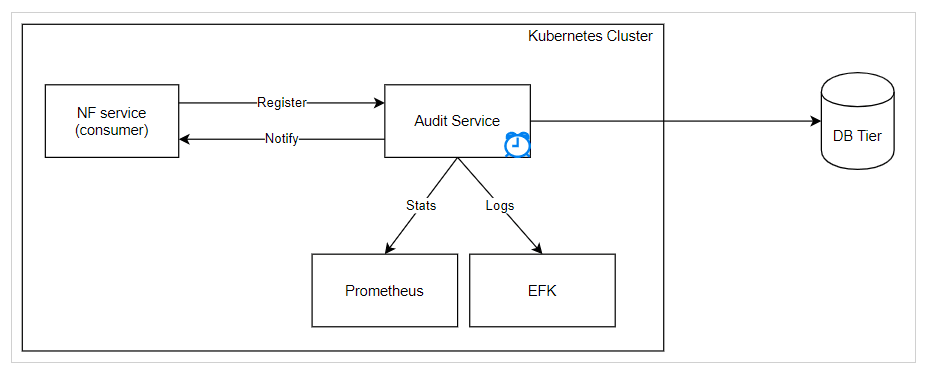
- BSF registers as a consumer with the Audit service and starts auditing the service database.
- When a stale record is detected, the Audit service takes any of
the following actions as requested by the BSF during the registration:
- Deletes the stale records from the database.
- Sends a notification to the service about the stale records.
- Deletes the stale records from the database and notify the service.
- The Audit service implements a minimum wait time between
consecutive audits and the consecutive notifications for the same record.
Note:
- The Audit service stores the service registration details in the DB to be recovered after the pod restart or upgrade.
- The audit service supports the local time zone.
Call Flow
Timeline View of Audit Service
Figure 3-35 Timeline view of Audit Service
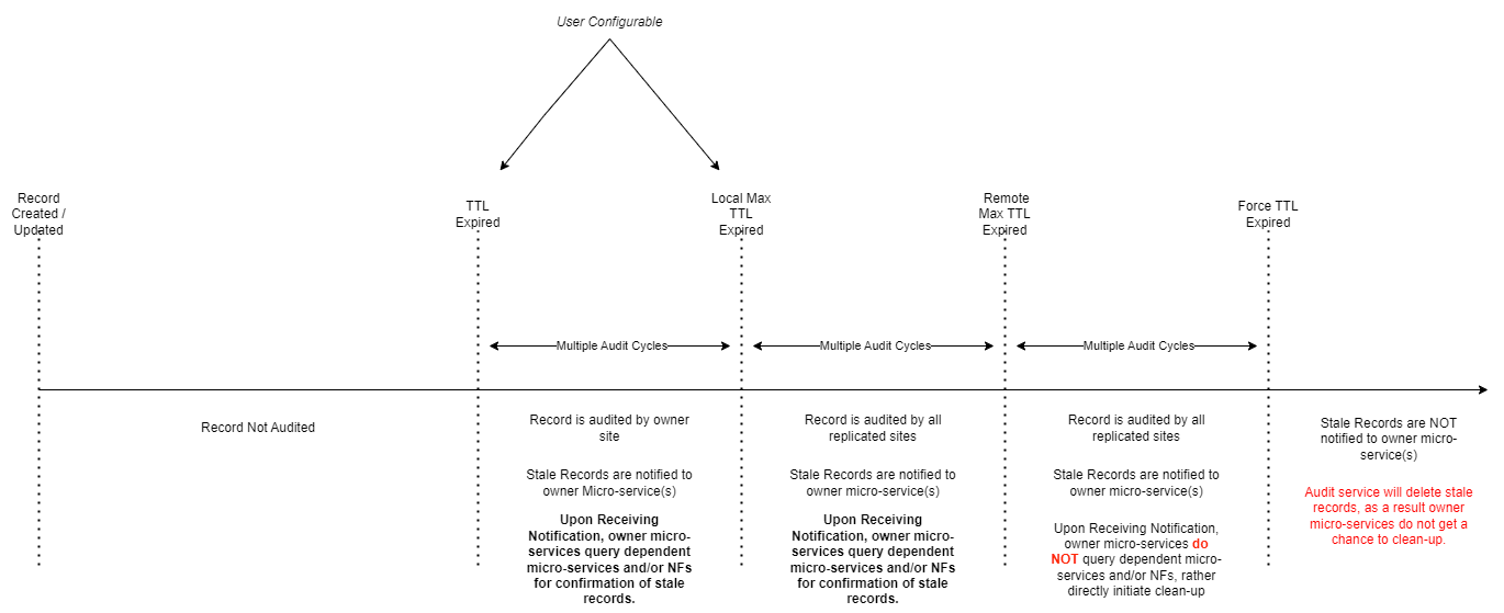
BSF identifies and deletes stale sessions in the following scenarios:
Query PCF to confirm a record as stale
Whenever Audit Service in BSF identifies a session which is soon to go stale (minimum Time-to-Live (minTTL) reached), Audit sends an audit notification request towards BSF Management service.
If Query to PCF is enabled, BSF sends a query to PCF to verify the corresponding session in PCF.
If PCF answers with a 404 (NOT FOUND) then BSF deletes the session.
"vendorSpecific-000111": {
    "version": 1,
    "notificationUrl": "<PCF Notification Url>",
    "createBindingTime": "<Timestamp>",
  }
BSF, in turn, uses this notification URI to send audit notification towards Binding service on PCF. When PCF receives the notification, it checks whether any binding record exists by sending a query to the Query service using contextId (SmPolicyAssociationId). Based on the findings, PCF sends 2xx response if session exists and 404 if the session does not exist.
A sample call flow for this scenario is shown below:
Figure 3-36 Query PCF to confirm a record as stale
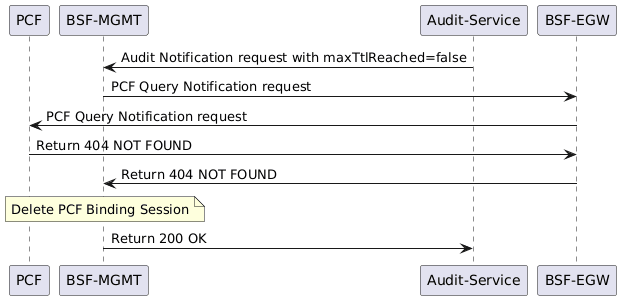
- Audit service identifies sessions which are soon to become stale (with minTTL reached) and sends a notification to BSF Management Service.
- If Query to PCF is enabled, BSF Management Service sends a query to PCF through Egress Gateway to check if the sessions exist in PCF.
- If the queried sessions are not present in PCF, PCF responds with
404 NOT FOUND. - BSF considers the session as stale and deletes them.
- BSF Management Service responds to Audit service with
200 OK.
Max TTL and minimum audit attempts reached
Whenever Audit Service in BSF identifies a session for which the Max Time-to-Live (maxTTL) is reached and has reached its minimum Audit Attempts too, Audit sends an audit notification requests towards BSF Management Service with its body value maxTtlReached as true. Whenever this request is received at BSF Management service, BSF deletes the session.
A sample call flow for this scenario is shown below:
Figure 3-37 Max TTL and minimum audit attempts reached
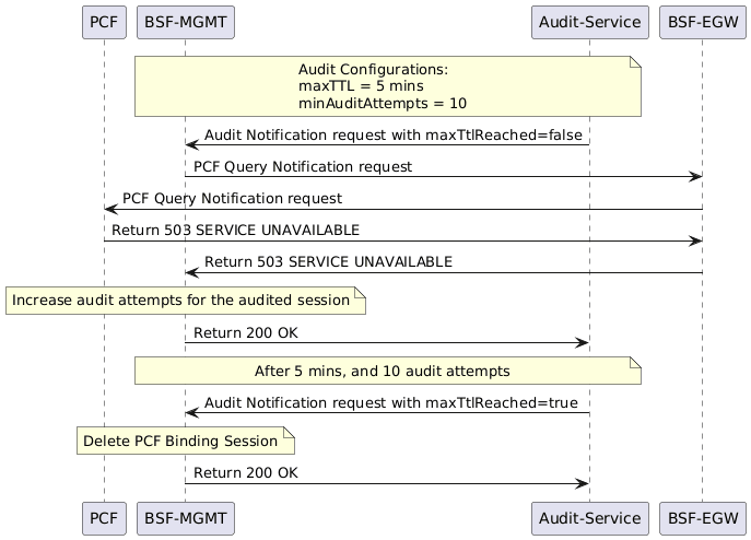
- Audit Service identifies the sessions that are soon to become stale and sends a notification to BSF Management Service with
maxTTLReached=false. - BSF Management Service sends a query to PCF through Egress Gateway to verify the corresponding sessions in PCF.
- If PCF responds with
503 SERVICE UNAVAILABLE, BSF Management Service increments the audit attempts for the audited session and responds to Audit Service with200 OK. - After exhausting the minimum audit attempts, when the maxTTL is reached (in the given example, minAuditAttempts=10 and maxTTL=5 mins), Audit Service sends a notification to BSF Management Service with
maxTTLReached=true. - BSF Management Service deletes the corresponding PCF Binding for the session from its database and responds to Audit Service with
200 OK.
Stale Session Notification from Diameter Gateway
Whenever BSF sends an AAR (can be either AAR-I or AAR-U) to Diameter Gateway to check for the existence of a session in the bound PCF, and PCF responds with an error, such as DIAMETER_UNABLE_TO_COMPLY, Diameter Gateway sends a delete request towards BSF through the /audit/notify API.
Whenever this request is received at BSF Management Service, BSF deletes the session.
A sample call flow for this scenario is shown below:
Figure 3-38 Stale Session Notification from Diameter Gateway
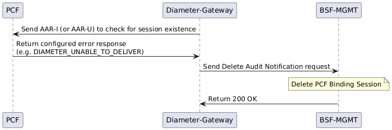
Enable
- Enable using Helm: To enable this feature during BSF
deployment, set the value of
auditServiceEnableparameter astruein theocbsf-22.2.0-custom-values.yamlfile. Once the Audit service is enabled, set appropriate values for the following parameters:- global.servicePorts.auditServiceHttp
- global.containerPorts.auditServiceHttp
- audit-service.envMysqlDatabase
For more information on how to customize these parameters, see Oracle Communications Cloud Native Core Binding Support Function Installation and Upgrade Guide.
- Enable using CNC Console: To enable this feature, on the Management Service page, under the Audit group, set the value of Enabled field as true. For more information about enabling the feature through CNC Console, see Service Configurations.
-
Enable using REST API: Set the audit.enable parameter value to true in the Management Service configuration API. For more information about enabling the feature through REST API, see the "Management Service" section in Oracle Communications Core Binding Support Function REST Specification Guide.
Configure
- Configure using CNC Console: Perform the feature configurations on the Management Service page. For more information, see Service Configurations.
- Configure using REST API: BSF provides the following
REST API for Stale Session Handling configuration:
API: {apiRoot}/oc-bsf-configuration/v1/services/managementservice
You can perform the GET and PUT operations to configure this feature. For more information about REST API configuration, see the "Management Service" section in Oracle Communications Core Binding Support Function REST Specification Guide.
Observe
- ocbsf_audit_notif_request_count_total
- ocbsf_audit_notif_response_count_total
- ocbsf_audit_delete_records_count_total
- ocbsf_diamgw_notification_request_count_total
- ocbsf_diamgw_notification_response_count_total
- ocbsf_query_request_count_total
- ocbsf_query_response_count_total
- ocbsf_bindingQuery_request_total
- ocbsf_bindingQuery_response_total
- ocbsf_bindingDelete_request_total
- ocbsf_bindingDelete_response_total
For more information, see the BSF Management service and Audit service metrics in the BSF Metrics section.
Maintain
BSF generates logs when audit service detects and removes stale sessions automatically. In addition, logs are printed for query requests towards PCF and the associated responses.
Stale Session Audit Retry
- Internal send failures
- SCP being unable to route a request to PCF
- PCF databases being out of sync, returning a 404 error
This may lead to unreliable or incorrect results regarding the existence of a PDU session. To prevent this, BSF allows for session retries within the same audit cycle. It uses Server Headers to identify the origin of an audit request failure and take appropriate action. Using NRF Client's On-Demand Discovery, it selects an alternate route and retries the audit request against a different PCF or SCP. The parameters Minimum required 404 responses and Expect 404 from different PCF can be set to decide the number of 404 responses, and if they must be from different PCF instances for a binding to be considered as stale.
BSF continues retrying till these conditions are met or until enough evidence is collected to mark a binding as stale. If all retries fail, it stops for that transaction and the binding is handled according to the audit decision logic.
Call Flows
Note:
The following diagrams are part of a single call flow which has been divided into separate sections.Figure 3-39 BSF Audit Notification Flow with EGW Rerouting and Alternate NF Discovery
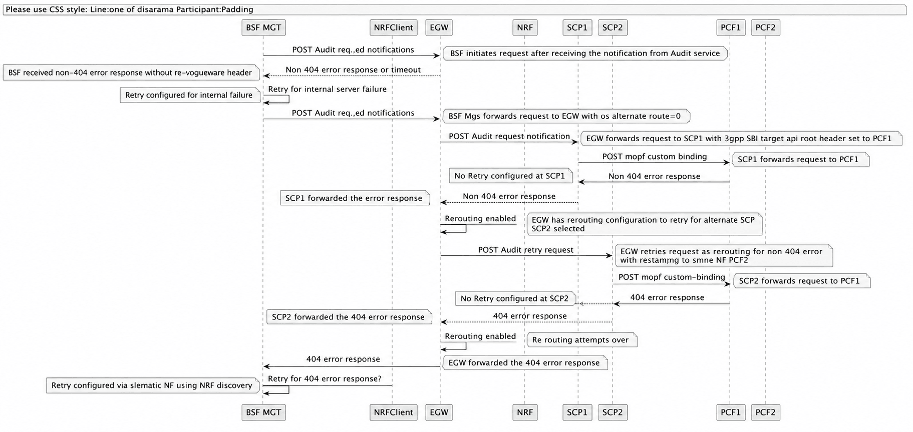
- BSF Management sends the POST audit request notification to Egress Gateway with the oc-alternate-route=0 header.
- Egress Gateway forwards the request to SCP1 and sets the 3gpp-Sbi-Target-apiRoot header to PCF1.
- SCP1 forwards the /npcf-custom-binding request to PCF1.
- PCF1 returns a non-404 error response to SCP1.
- SCP1 does not retry the request and forwards the non-404 error response back to the Egress Gateway.
- The Egress Gateway detects that SbiRouting retry is enabled and selects SCP2 as the alternate SCP for retry.
- The Egress Gateway sends a POST audit retry request to SCP2.
- SCP2 forwards the /npcf-custom-binding request to PCF1 again.
- PCF1 returns a 404 error response to SCP2.
- SCP2 does not retry the request and forwards the 404 error response back to the Egress Gateway.
- The Egress Gateway determines that all rerouting attempts are complete and forwards the 404 error response to BSF Management.
- BSF Management checks whether retry handling is configured for 404 errors through alternate NF discovery.
- BSF Management initiates NRF discovery using SetId and NFType to locate an alternate NF.
- If BSF receives a non-404 error response or timeout without the oc-egw-route header during the initial request, BSF performs an internal retry based on the configured retry policy.
Figure 3-40 On-Demand NF Discovery Flow with NRF Client Caching
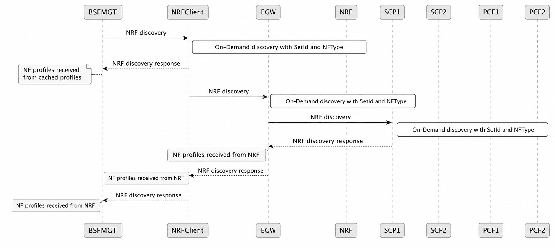
Scenario 1: On-demand NF discovery with NRF Client caching enabled
- BSF Management requests NF discovery from the NRF Client.
- The NRF Client checks its local cache for valid NF profiles.
- If valid cached NF profiles are available, the NRF Client returns the cached NF discovery response to BSF Management.
- If the cache entry is expired or unavailable, the NRF Client sends a fresh NF discovery request to the NRF.
- The NRF returns the updated NF profiles to the NRF Client.
- The NRF Client updates its local cache with the latest NF profiles.
- The NRF Client returns the updated NF discovery response to BSF Management.
- BSF Management sends an NRF discovery request to NRF Client.
- The NRF Client initiates on-demand discovery using SetId and NFType.
- The NRF Client forwards the NRF discovery request to the NRF.
- NRF performs on-demand discovery using SetId and NFType.
- NRF returns the NRF discovery response to the NRF Client.
- NRF Client forwards the NF profiles received from the NRF to BSF Management.
- BSF Management receives the NRF discovery response containing NF profiles from the NRF.
Figure 3-41 BSF Audit Retry Flow with Alternate NF Selection and 404 Error Handling
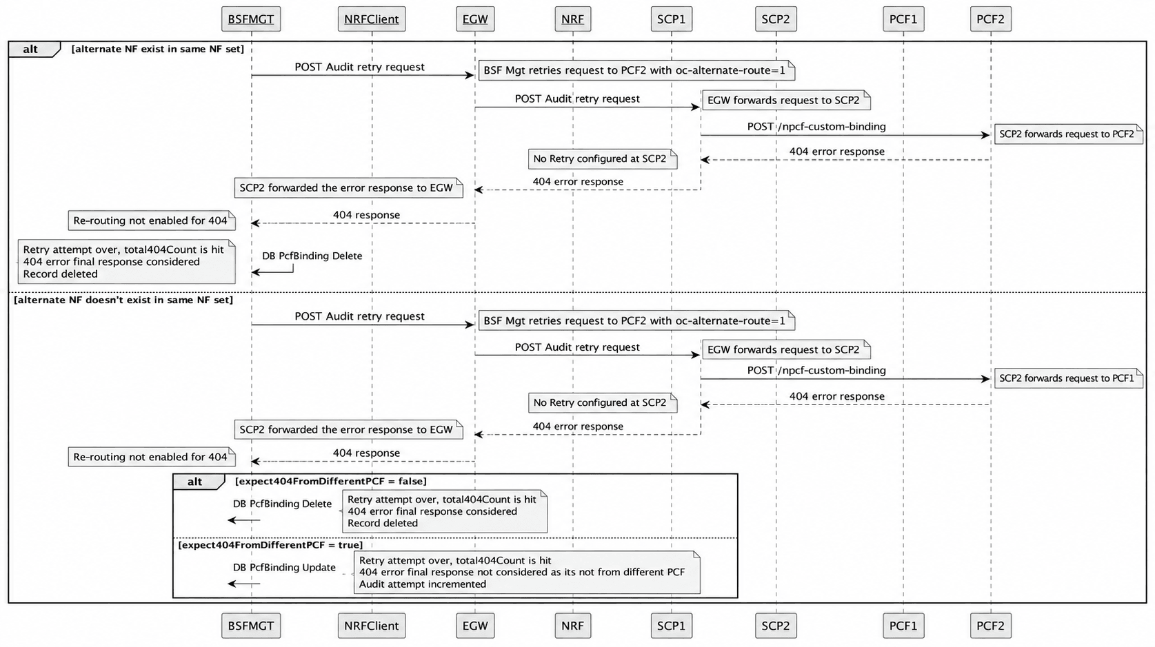
- BSF Management sends a POST audit retry request to the Egress Gateway for PCF2 with the oc-alternate-route=1 header.
- Egress Gateway forwards the POST audit retry request to SCP2.
- SCP2 forwards the /npcf-custom-binding request to PCF2.
- PCF2 returns a 404 error response to SCP2.
- SCP2 does not retry the request and forwards the 404 error response to the Egress Gateway.
- Egress Gateway forwards the 404 error response to BSF Management because rerouting is not enabled for 404 errors.
- BSF Management determines that the retry attempt is complete and that the configured total404Count limit has been reached.
- BSF Management treats the 404 error as the final response and deletes the PCF binding record from the database.
- BSF Management sends a POST audit retry request to the Egress Gateway for PCF2 with the oc-alternate-route=1 header.
- Egress Gateway forwards the POST audit retry request to SCP2.
- SCP2 forwards the /npcf-custom-binding request to PCF1.
- PCF1 returns a 404 error response to SCP2.
- SCP2 does not retry the request and forwards the 404 error response to the Egress Gateway.
- Egress Gateway forwards the 404 error response to BSF Management as rerouting is not enabled for 404 errors.
Enable
To enable BSF to discover PCF instances, the PCF must register with the NRF and include BSF in the allowedNFTypes parameter of its NF Profile. This allows BSF, as a consumer NF, to discover the registered PCF instances.
- NF FQDN
- Service FQDN and Port
- Service IP Endpoints
- Service API versions and schemes (HTTP/HTTPS)
Note:
For the BSF audit notification feature, the PCF must register the Npcf_SMPolicyControl service with the NRF.
- Enable using CNC Console: To enable this feature, under Management Service page, under the Audit section, set the values of Enabled and Query to PCF fields as true. Additionally, set relevant values for the fields Minimum required 404 responses, Expect 404 from Different PCF and PCF Communication Profile. For more information about enabling the feature through CNC Console, see Service Configurations.
- Enable using REST API: In the Management Service configuration API, set the values of parameters
audit.enableandqueryToPcfto true. Additionally, set relevant values for the parameterstotal404Count,expect404FromDifferentPCFandpcfNfCommProfile.
Configure
- Configure using CNC Console: Perform the feature configurations on the following pages:
- Retry Profile
- NF Communication Profile
- NRF Agent Service
- Management Service
- Configure using REST API: BSF provides the following REST APIs for Stale Session Audit Retry configuration:
- API: {apiRoot}/oc-bsf-configuration/v1/services/retryprofiles
- API: {apiRoot}/oc-bsf-configuration/v1/services/nfcommprofiles
- API: {apiRoot}/oc-bsf-configuration/v1/services/nrfAgentServiceConfig
- API: {apiRoot}/oc-bsf-configuration/v1/services/managementservice
Note:
- If the BSF attempts to route the request to PCF1 and receives an error, it retries using the alternate route to PCF2, which returns a successful response. However, if the 3gpp-Sbi-Target-apiRoot header is not included in the response, the PCF notification URL will not be updated in the PcfBinding record. As a result, during the subsequent audit, the BSF will again make the initial attempt to PCF1.
- In the case of an alternate routing attempt, the 3gpp-Sbi-Routing-Binding header will not be updated with the selected NF profile’s NF Instance ID. Instead, the header will retain the same value that was used in the original request.
- Enabling the Retry and Reroute feature requires the nfdiscovery application to be deployed as part of the BSF deployment to support NRF on-demand discovery calls from NRF-Client to NRF. This will increase the overall resource consumption of the BSF deployment, and the application resource's requirement may need to be updated accordingly. Additionally, since retry is not implemented between the BSF Management service and NRF-Client’s NFDiscovery interface, any failure during on-demand discovery will cause the retry procedure for the audit request to fail, and the response from the initial attempt will be treated as the final response.
- The feature of SCP selection depends on Monitoring the Availability of SCP using HTTP2 OPTIONS (Health check API).
- When this feature is enabled, SCP retry/reselection should be disabled. SCP connected to the PCF has the capability to re-select Target NFs based on NFSet. It cannot re-select another SCP and forward the message to an alternate SCP. It can only re-select another producer from the NF Set.
- By default, the service name in the NF On-Demand Discovery (ODD) request is populated from the binding header. If the binding header does not contain the service name, the default service name is used. Since this discovery parameter is optional, it can be disabled by setting the advanced setting ENABLE_DISCOVERYPARAM_SERVICE_NAMES to false.
- When enabled in the NfCommProfile, the callback header is sent with the default value Nbsf_Management_myNotification. This value can be overridden by configuring the advanced setting SBI_CALLBACK_HEADER_VALUE with the desired callback header value.
Observe
- ocbsf_ar_request_total
- ocbsf_ar_response_total
- ocbsf_ar_failure_total
- ocpm_nfDiscovery_request_total
- ocpm_nfDiscovery_response_total
- ocbsf_query_request_count_total
- ocbsf_query_response_count_total
3.34.1 Enhanced Logging of BSF Stale Binding Deletion
- Reason for deleting the stale session:
- 404 Response received from PCF
- Max TTL Reached
- Stale Session Notification received from Diameter Gateway
- Policy binding session details such as:
- bindingId
- SUPI
- GPSI
- DNN
- UE IP address:
- IPv4
- IP Domain
- IPv6 Prefix
- Policy FQDN
- Policy Instance ID
- Policy Set ID
- SNSSAI
- Policy Diameter Host
- Policy Diameter Realm
- Created Date Time
- Last Audited Date Time
- Audit Attempts
For example:
{
	bindingId: 671df805-8a48-4711-ba23-fdbf198b3fa7,
	supi: imsi-311480611009999,
	gpsi: msisdn-19544398580,
	dnn: abcinternet,
	ipv4Addr: 140.0.0.1,
	ipv6Prefix: 2607:f160:3e:6d:0:0:0:0/64,
	pcfFqdn: oc-diam-gateway,
	pcfId: fe7d992b-0541-4c7d-ab84-c6d70b1b0420,
	snssai: 1-000007,
	pcfDiamHost: oc-diam-gateway,
	pcfDiamRealm: oracle.com,
	createdDateTime: 2025-06-11T07:25:56.701652Z,
	lastAuditedDateTime: 2025-06-11 07:25:57.0,
	auditAttempts: 0
}
Note:
Details with null values are not included in logs.Managing the Enhanced Logging of BSF Stale Binding Deletion
Enable
Enhanced logging for BSF stale binding deletion can be enabled either using CNC Console or using REST API.
Enable using CNC Console:
Configure Log Level for Stale Session Deletions field under Enhanced Logging Configuration section on General Settings page for General Configurations in CNC Console for BSF.
The Log Level for Stale Session Deletions field specifies the log level for stale session deletions.
Figure 3-42 Log Level for Stale Session Deletions
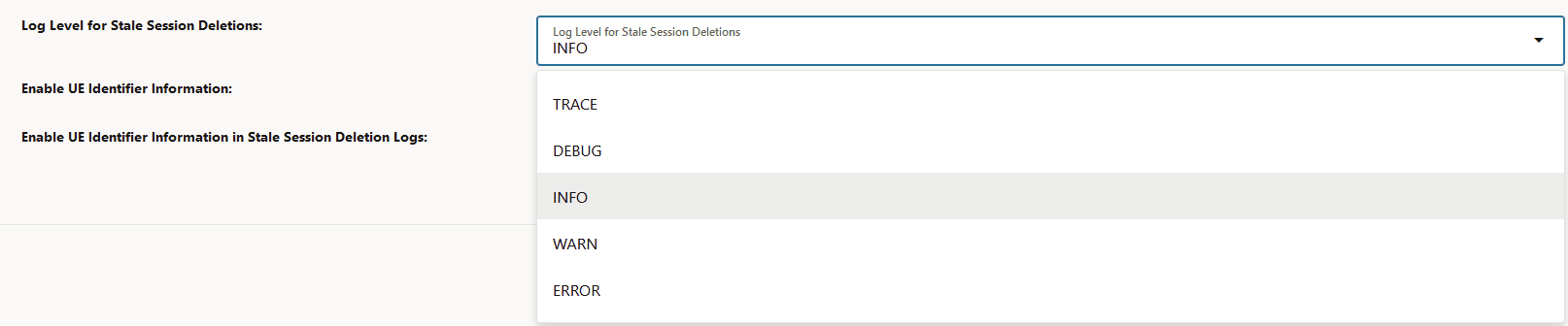
- TRACE
- DEBUG
- INFO
- WARN
- ERROR
The logs for BSF stale binding deletion are generated at the specified level.
Note:
The value of this field does not modify in any way the log level that BSF Management service has. The root log level of BSF Management service must be either the same log level defined in the selected or lower for these deletion logs to appear. For example, if the stale session deletions log level is at INFO, then BSF Management service log level must be either TRACE, DEBUG, or INFO.
For more information, see General Settings.
Enable using REST API
Configure
enhancedLogging.staleSessionDeletionLogLevel parameter for
General Configurations API.
The General Configurations API can be accessed using
{apiRoot}/oc-bsf-configuration/v1/general/export.
For more information, see General Configurations section in Oracle Communications Core Binding Support Function, REST Specification Guide.
Configure
Enhanced logging for BSF stale binding deletion can be enabled either using CNC Console or using REST API.
Using CNC Console:
Contents of the logs can be configured by configuring the following fields under Enhanced Logging Configuration section on General Settings page for General Configurations in CNC Console for BSF.
- Log Level for Stale Session Deletions: Specifies the log level for stale session deletions. By default, the log level for stale session deletions is at INFO level.
- Enable UE Identifier Information in Stale Session Deletion
Logic: Specifies whether to enable or disable UE Identifier
information in stale session deletion logging. When this field is disabled, the UE
Identifier information in the logs are masked. That is, the identifier information
appears like 'xxxx'.
By default, this field is disabled.
Sample logs when Enable UE Identifier Information in Stale Session Deletion Logic is disabled:{ "bindingId": "b75b4c43-0636-485f-b9e4-26fb6eea97ca", "supi": "XXXX", "gpsi": "XXXX", "dnn": "dnn2", "ipv4Addr": "XXXX", "pcfFqdn": "pcf-smservice. oracle .com", "snssai": { "sst": 11, "sd": "abc123" }, "pcfDiamHost": "pcf-smservice. oracle .com", "pcfDiamRealm": "oracle .com" }Sample logs when Enable UE Identifier Information in Stale Session Deletion Logic is enabled:{ "bindingId": "b75b4c43-0636-485f-b9e4-26fb6eea97ca", "supi": "imsi-311411000000002", "gpsi": "msisdn-5084948009", "dnn": "dnn2", "ipv4Addr": "10.10.10.2", "pcfFqdn": "pcf-smservice.oracle.com", "snssai": { "sst": 11, "sd": "abc123" }, "pcfDiamHost": "pcf-smservice.oracle.com", "pcfDiamRealm": "oracle.com" }
For more information, see General Settings.
Using REST API
To configure enhanced logging for BSF stale session deletions, configure
enhancedLogging section in General Configurations API.
The General Configurations API can be accessed using
{apiRoot}/oc-bsf-configuration/v1/general/export.
For more information, see General Configurations section in Oracle Communications Core Binding Support Function, REST Specification Guide.
3.35 Support Multiple Cluster Deployment at CNC Console
The CNC Console supports both single and multiple cluster deployments.
In a single cluster deployment, the CNC Console can manage NFs and Oracle Communications Cloud Native Core, Cloud Native Environment (CNE) common services deployed in the local Kubernetes clusters.
In a multiple instances deployment, the CNC Console can manage multiple BSF instances and CNE common services deployed within a Kubernetes cluster. For more information about single and multiple cluster deployments, see Oracle Communications Cloud Native Core, Cloud Native Configuration Console Installation, Upgrade, and Fault Recovery Guide.
The following image represents a Kubernetes cluster with one instance of CNC Console and two instances of BSF. The single instance of the CNC Console is configuring two instances of BSF with different namespaces.
Figure 3-43 Support for Multiple Instance Deployment
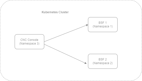
With the support of multicluster deployment, BSF deployed in multiple Kubernetes clusters can be accessed using CNC Console. In a multicluster deployment, the CNC Console can manage BSF and OCCNE common services deployed in the remote Kubernetes clusters.
The following image represents multiple Kubernetes clusters with one CNC Console and two BSF deployments. The single instance of CNC Console is configuring two instances of BSF with different namespaces deployed in different clusters.
Figure 3-44 Support for Multicluster Deployment
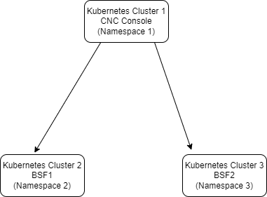
3.36 Support for 3GPP NF Sets and Binding Headers
Oracle Communications Cloud Native Core Binding Support Function supports the 3GPP NF Sets and Binding Headers in Model-B (Direct communication) and Model-C (Indirect communication). Using this feature, BSF can construct and send a binding header in the response messages to PCF for successful call processing.
Note:
Since BSF is a producer NF, it does not send any notifications to consumer NFs. BSF sends an HTTP request message only to NRF for management purpose.NF Set: NF set is a group of interchangeable NF instances supporting similar services and network slices. In an NF set, the NF instances can be geographically distributed, but have access to the same context data. The NF instances can be deployed in such a pattern so that several instances are present within an NF set to provide distribution, redundancy, and scalability as a set. The NF instances of an NF set are equivalent and share the same MCC, MNC, NID (for SNPN), NF type, and NF Set ID.
Binding Headers: The Binding headers indicate the suitable target NF producer instance for NF service instance selection, reselection, and routing of subsequent requests associated with a specific NF producer resource or context. It allows the NF producer to indicate that the NF consumer, for a particular context, should be bound to an NF service instance, or NF set depending on local policies. Binding can also be used by the NF consumer to indicate the suitable NF consumer instances for notification target instance reselection and routing of subsequent notification requests, associated with a specific notification subscription.
Table 3-35 Supported Headers
| Header Name | Description |
|---|---|
| 3gpp-Sbi-Binding |
This header is used to communicate the binding information from an HTTP server for storage and subsequent use by an HTTP client. This header contains a comma-delimited list of Binding Indications from an HTTP server for storage and use of HTTP clients. The absence of this parameter in a Binding Indication in a service request is interpreted as "callback". Note: In the current release, the following
are not supported:
|
Binding Support Function supports the NF Set and Binding Header functionality in all SBI interfaces.
Example
Figure 3-45 Example of NF Set and Binding Header in BSF
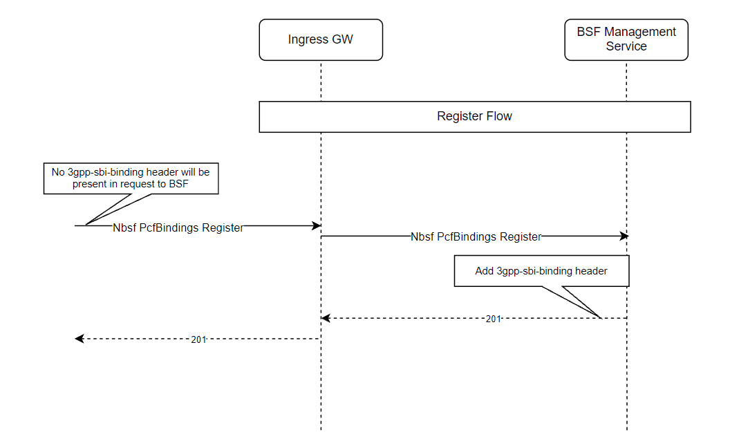
The above call flow diagram describes a scenario where PCF sends a request
to register PcfBindings towards the BSF Management service through Ingress Gateway. The
register request does not contain a 3gpp-sbi-binding header.
Once the request is received at BSF, the BSF Management service adds
3gpp-sbi-binding to the response and sends it back to the PCF with
HTTP status code 201.
If the user does not want to add a binding header to response messages, then it can be configured through CNC Console or REST APIs for BSF.
Managing NF Sets and Binding Header Support
Enable and Configure
The NF Sets and Binding header support can be enabled and configured for the BSF Management service interface using any of the following two ways:
- Using CNC Console: Perform the feature configurations on the NF Communication Profile page. NF Communication Profile must be attached to PCF Communication Profile under the Audit section of the Management Service page. For more information about the configurations, see Service Configurations.
- Using REST API: BSF provides the following REST API for NF Sets and Binding Headers configuration:
API: {apiRoot}/oc-bsf-configuration/v1/services/nfcommprofiles
You can perform the GET and PUT operations to configure this feature. For more information about REST API configuration, see the "Management Service" section in Oracle Communications Cloud Native Core Binding Support Function REST Specification Guide.
Observe
ocpm_ingress_request_totalwith the new dimensions –pcf_idandpcf_set_idNote:
The dimensions are populated only for Nbsf_Management_Register requests.ocpm_ingress_response_totalwith the new dimensions –binding_levelandbinding_id
Maintain
The BSF logs include the NF binding information sent by BSF. The logs include information about the following headers:
location3gpp-sbi-binding
{
  "instant": {
    "epochSecond": 1636550691,
    "nanoOfSecond": 280882458
  },
  "thread": "XNIO-1 task-1",
  "level": "DEBUG",
  "loggerName": "ocpm.bsf.api.management.controller.BindingSupportManagementServiceAPIController",
  "message": "PCF binding: PcfBinding [supi=imsi-411411000000011, gpsi=5084948001, ipv4Addr=10.10.10.16, ipv6Prefix=null, ipDomain=null, macAddr48=null, dnn=internet, pcfFqdn=pcf-smservice.oracle.com, pcfIpEndPoints=null, pcfDiamHost=pcf-smservice.oracle.com, pcfDiamRealm=oracle.com, snssai=Snssai [sst=11, sd=abc123], pcfId=fe7d992b-0541-4c7d-ab84-c6d70b1b0123, pcfSetId=setxyz.pcfset.5gc.mnc015.mcc345, bindLevel=NF_SET]",
  "endOfBatch": false,
  "loggerFqcn": "org.apache.logging.slf4j.Log4jLogger",
  "threadId": 45,
  "threadPriority": 5,
  "messageTimestamp": "2021-11-10T13:24:51.280+0000"
}
3.37 Support for User-Agent Header
User-Agent header helps the producer Network Function (NF) to identify the consumer NF that has sent the request. To implement this, 3GPP introduced the use of User-Agent header for consumers to include the same in service requests. Additionally, producers may require to support the validation of the User-Agent headers to complete the request identification process in the network.
With the integration of this feature, User-Agent header helps the producer Network Function (NF) to identify the consumer NF that has sent the request.
<NF Type>-<Instance-Id> <FQDN>
where, <NF Type> is the type of the Network
Function.
<Instance-Id is the instance ID of the NF.
<FQDN> is the FQDN of the NF.
Example:
BSF-54804518-4191-46b3-955c-ac631f953ed8 bsf1.east.5gc.mnc012.mcc234.3gppnetwork.org
- If the user-agent header is present, then it is matched with the configured NF types. If a match is found, then validation is successful and request is allowed to pass. If a match is not found, then request is rejected with a configurable error code.
- If the user-agent header is present and has multiple values, then the request is rejected with a configurable error code. Hence, the user-agent header, if present should have a single value.
- If the user-agent header is not present and validationType is relaxed, then validation is not made and request is allowed to pass. If validationType is strict, then request will be rejected with a configurable error code.
Managing Support for User-Agent Header in Ingress Gateway
Enable
- Helm: Set the value of the parameter userAgentHeaderValidationConfigMode to Helm in the custom-values.yaml file. For more information, see the Oracle Communications Cloud Native Core Binding Support Function Installation and Upgrade Guide.
- REST API: Set the value of the parameter userAgentHeaderValidationConfigMode to REST in the custom-values.yaml file. REST configuration from the JSON bodies sent to path: "/bsf/nf-common-component/v1/igw/useragentheadervalidation" is stored in a database under the common_config table. For more information, see the Oracle Communications Cloud Native Core Binding Support Function REST Specification Guide.
Configure
You can configure the User-Agent Header using REST or Helm.
#User-Agent header validator configuration
#Mode of configuration. Can be either HELM or REST
userAgentHeaderValidationConfigMode: HELM
userAgentHeaderValidation:
  enabled: true
# If User-Agent header is not present or it's value is null in the incoming request then
validation type can be used to skip or perform validation. If set to strict then validation will be performed.
# If set to relaxed then validation will be skipped.
 validationType: relaxed
# List of consumer NF Types to be matched against the value of User-Agent header in the request
 consumerNfTypes:
   - "SMF"
   - "AMF"
   - "UDR"
      ...
To configure the User-Agent header at Ingress Gateway using REST API, see user-Agent Header in Oracle Communications Cloud Native Core Binding Support Function REST Specification Guide.
Managing Support for User-Agent Header in Egress Gateway
Enable
- Helm: Set the value of the parameter userAgentHeaderConfigMode to Helm in the custom-values.yaml file. For more information, see the Oracle Communications Cloud Native Core Binding Support Function Installation and Upgrade Guide.
- REST API: Set the value of the parameter userAgentHeaderConfigMode to REST in the custom-values.yaml file. REST configuration from the JSON bodies sent to path: "/bsf/nf-common-component/v1/egw/useragentheader" is stored in a database under the common_config table. For more information, see the Oracle Communications Cloud Native Core Binding Support Function REST Specification Guide.
Configure
You can configure the User-Agent Header using REST or Helm.
userAgentHeaderConfigMode: HELM
userAgentHeader:
  enabled: false # flag to enable or disable the feature
  nfType: "PCF" # NF type of consumer NF
  nfInstanceId: "2d8e8e68-24ad-11ed-861d-0242ac120002" # NF type of consumer NF
  addFqdnToHeader: true # Flag to add fqdn. If enabled then user-agent header will be
generated along with the fqdn configured otherwise fqdn will not be added
  nfFqdn: "oracle1.pcf.pacific.org" #fqdn of NF. This is not the fqdn of gateway
  overwriteHeader: true

oauthClient:
  enabled: false
  nfInstanceId: fe7d992b-0541-4c7d-ab84-c6d70b1b01b1
  nfType: PCF
To configure the User-Agent header at Egress Gateway using REST API, see user-Agent Header in Oracle Communications Cloud Native Core Binding Support Function REST Specification Guide.
Observe
- oc.ingressgateway.http.requests
For more information, see User-Agent Header Metrics section.
3.38 Support for Active Sessions Counter
Active sessions are the unique PCF binding sessions in every BSF instance.
Note:
The active sessions count also includes stale sessions until BSF removes it from its local database.
For more details on how stale sessions are handled, see Handling Stale Session in BSF.
Figure 3-46 Retrieving Active Sessions Count
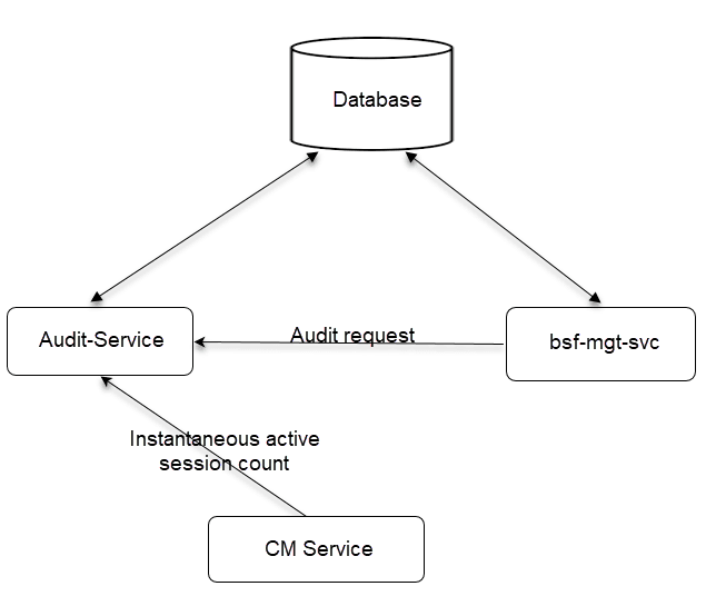
The Audit-Service periodically counts the simultaneous unique active sessions, over a configurable period of time. The default value of the time period is set to 15 mins. The time period can be configured to any value between 1 to 60 minutes.
The bsf-mgt-svc requests the Audit-Service to count active
sessions for configurable time period. The Audit-Service periodically finds active
sessions count and publishes the count as a metric.
To get the instantaneous value of active sessions count, you can query the CM service, which internally calls Audit-Service to fetch the value.
Figure 3-47 Active Sessions Count
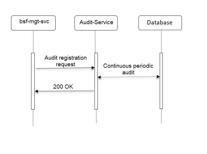
Note:
The audit registration process is used to register for audit registration as well as to enable active sessions counting.
The bsf-mgt-svc sends an audit registration request to the
Audit-Service.
If the registration is successful, the Audit-Service responds with a 200 OK message.
If the registration fails due to any issue with the request, the Audit-Service responds with a Bad Request - 400 message.
If the registration fails due to any other internal reason while processing the request, the Audit-Service responds with an Internal Server Error - 500 message.
Note:
Audit registration is not required for CM Service to query the instantaneous active sessions count.
Once the registration is successful, the Audit-Service periodically finds active sessions count and publishes the count as a metric.
Figure 3-48 Get Instantaneous Active Sessions Count - Successful
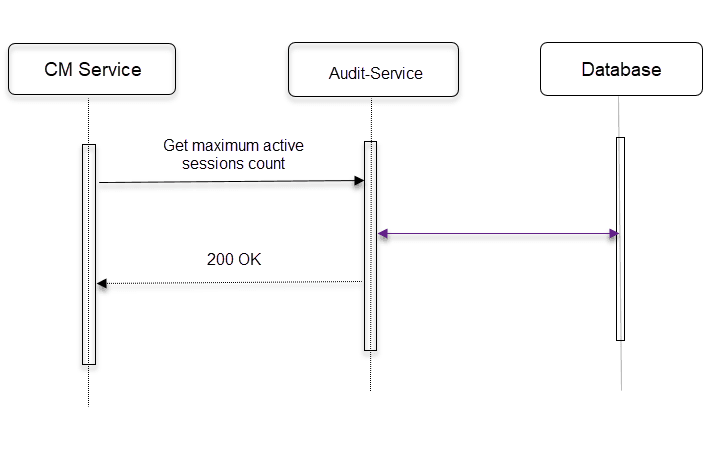
The CM Service sends a Get maximum active sessions count
request to Audit-Service.
If the CM Service call to Audit-Service is successful, it responds with a 200 OK message.
Figure 3-49 Get Instantaneous Active Sessions Count - Failure
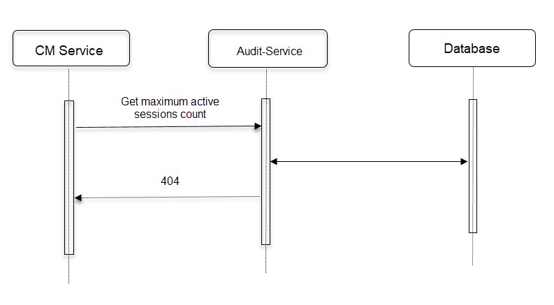
If the CM Service call to Audit-Service fails, it responds with a 404 message.
ENABLE
You can enable the Active Sessions Counter feature using CNC Console or REST API.
-
Using CNC Console: Set the value of Count Active Sessions parameter to
trueon Active Sessions Counting page. For more details, see Active Sessions Count under Service Configurations section. - Using REST API: BSF provides the following REST API for Active Sessions
Counter configuration:
API: {apiRoot}/oc-bsf-configuration/v1/services/managementservice
You can perform the GET and PUT operations to configure this feature.
To enable the feature, set the value of
activeSessionCounting.countRecordsparameter totrue.For more details, see BSF REST Specifications section in Oracle Communications Cloud Native Core Binding Support Function REST Specification Guide.
For more information, see Active Session Query.
Configure
You can configure the Active Sessions Counter feature using CNC Console or REST API.
-
Using CNC Console: Set the value of Session Count Interval (in minutes) parameter on Active Sessions Counting page. You can set the time interval to any value between 1 to 60 minutes. For more details, see Active Sessions Count under Service Configurations section.
For instantaneous query, use the Active Session Query tab under Status and Query in CNC Console.
For more information, see Active Session Query.
- Using REST API: BSF provides the following REST API for Active Sessions
Counter configuration:
API: {apiRoot}/oc-bsf-configuration/v1/services/managementservice
You can perform the GET and PUT operations to configure this feature.
To configure the feature, set the value of
activeSessionCounting.countRecordsIntervalparameter.For instantaneous query, BSF provides the following REST API:
API: {apiRoot}/oc-bsf-configuration/v1/activeSessionCount/pcfBindings
You can perform the GET operation to retrieve the instantaneous active sessions count.
For more details, see BSF REST Specifications section in Oracle Communications Cloud Native Core Binding Support Function REST Specification Guide.
Observe
- oc_db_active_session_count
- inbound_requests_total
For more information, see Active Sessions Count Metrics.
3.39 Controlled Shutdown of an Instance
CNC BSF supports controlled shutdown feature to provide the partial or complete isolation of the site from the network so that the operator can perform the necessary maintenance and recovery procedures when required. It helps the operator to perform the recovery procedures as per the requirement.
The site isolation is achieved by shutting down the load at gateways (Ingress Gateway, Egress Gateway, and Diameter Gateway) and updating the NF status as SUSPENDED at NRF.
Operational State
The site can be in one of the three possible operational states NORMAL, PARTIAL SHUTDOWN, or COMPLETE SHUTDOWN. The operational state can move to any of the states from the current state, there is no definitive order of state change. Currently, the operational state is stored in the common config server of the Ingress Gateway. It is read by Ingress Gateway, Egress Gateway, Diameter Gateway, and App-info periodically and action is triggered based on the current state.
Note:
Since the operational state is stored in config server, the service instances will detect the state change after the config refresh is done. If the config refresh interval is set as 5 seconds, then the pods may recognize the operational state change after 5 seconds.- Ingress Gateway
- Egress Gateway
- Diameter Gateway
- App-info
- Audit Service
Note:
If the Disaster Recovery procedure is performed when the config backup was taken when the system was in PARTIAL or COMPLETE SHUTDOWN state, then manual intervention may be required to change the operational state back to NORMAL state.Load Control
Note:
When the system is in COMPLETE SHUTDOWN state, audit service triggered notification or diameter messages will be rejected at respective gateways.Call Flow for Diameter Gateway
NORMAL State: If the Controlled shutdown operational state is NORMAL, then the Diameter Gateway processes the message as normal.
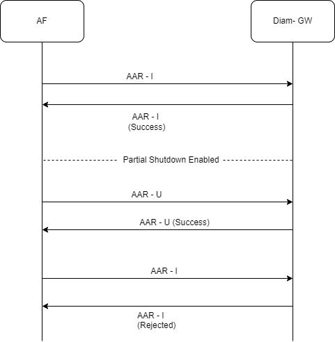
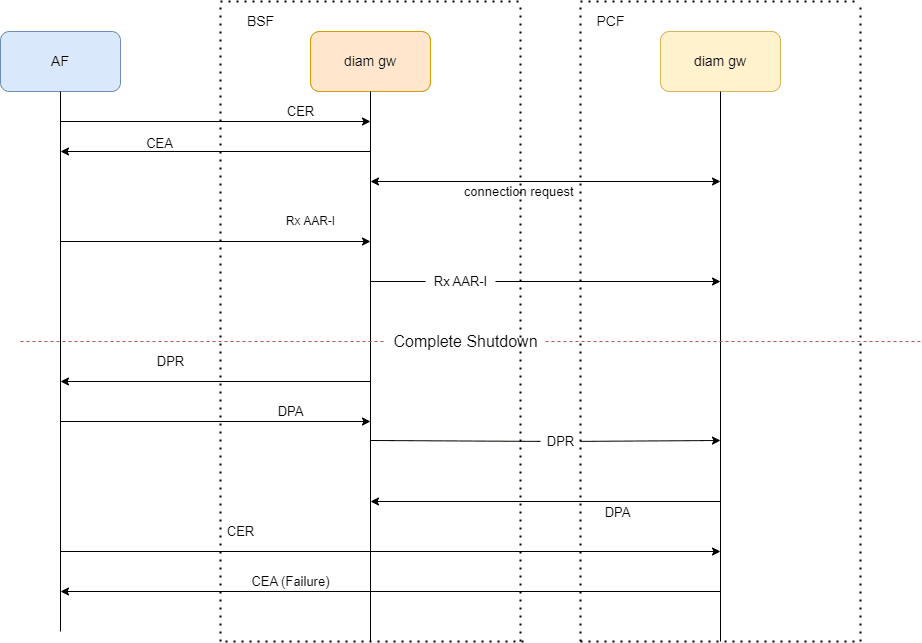
Call Flow for Egress Gateway
NORMAL State: If the Controlled shutdown operational state is NORMAL, then the Egress Gateway processes the message as normal.
PARTIAL SHUTDOWN: If the controlled shutdown operational state is PARTIAL SHUTDOWN, then the Egress Gateway processes the message as normal.
- Forward all requests received from NRF Client.
- Reject all requests received from any other services like UDR Connector, SM Service, AM Service, UE Service, and CHF Connector.
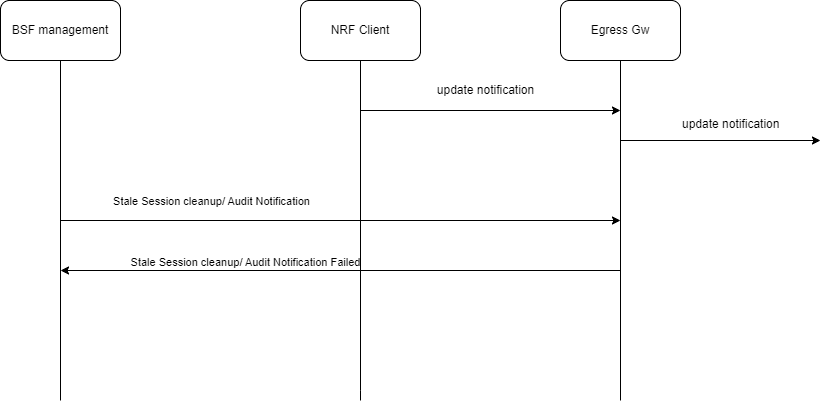
Call Flow for Ingress Gateway
NORMAL State: If the Controlled shutdown operational state is NORMAL, then the Ingress Gateway processes the message as normal.
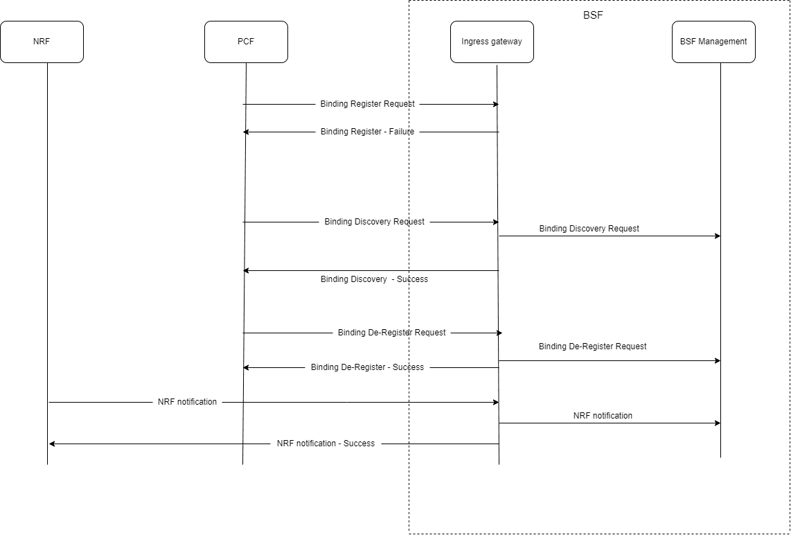
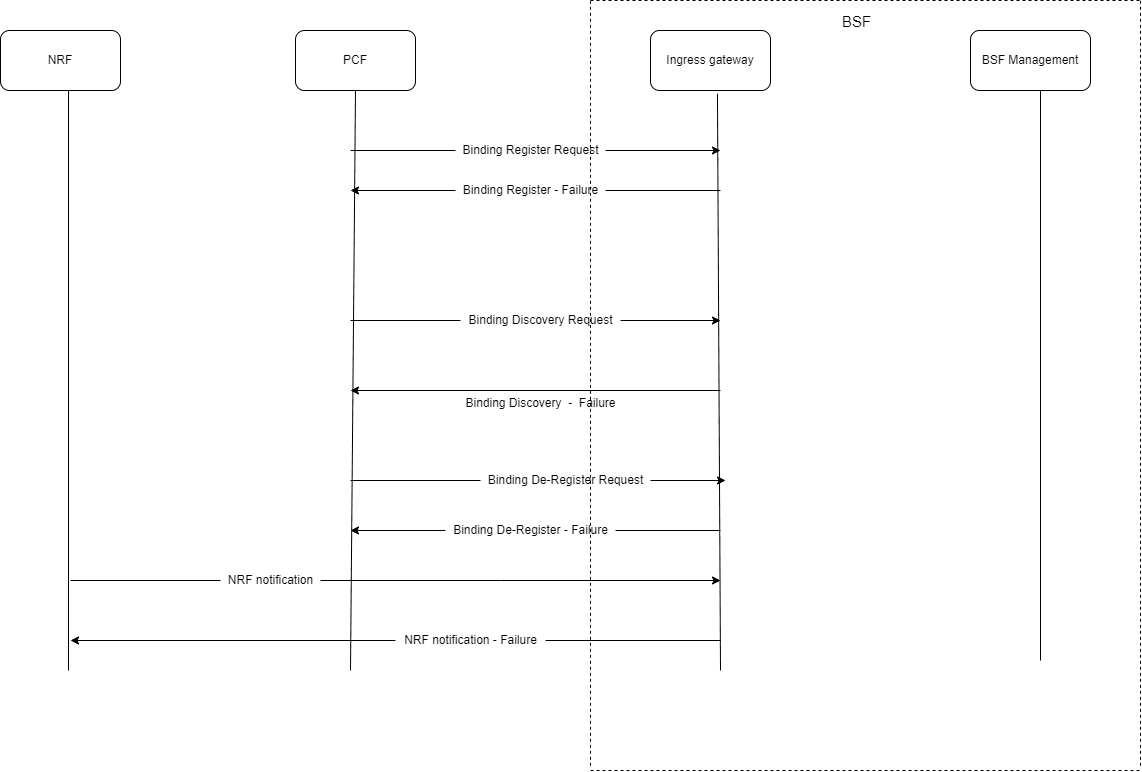
Audit Service
The Disabling Audit on Controlled Shutdown feature allows you to gracefully shut down audit and timer services in a controlled manner. When enabled, this feature ensures that during a COMPLETE_SHUTDOWN, the Audit Service and Timer Service are temporarily disabled, preventing interruptions and ensuring a smooth shutdown process. This feature is particularly useful for maintenance or upgrade scenarios where you need to pause auditing activities without losing data or disrupting ongoing operations.
Depending on the operationalState, the system behaves as follows:
- NORMAL / PARTIAL_SHUTDOWN: Audit and Timer Services continue to function as usual.
- COMPLETE_SHUTDOWN:
- Audit Service: All audit operations are interrupted,
including stale session notifications and record deletions. All entries
in
audit_schedule_tableare transitioned toCTRL_SHUTDOWN_INTRPTstate, except those already in DEREGISTERED or INTERRUPTED states. The Audit Now and Audit Resume functionalities are disabled. But, the Audit Pause functionality remains enabled. The audit service supports registration, deregistration, and fetch requests. - Timer Service: Timer expiry is disabled. The timer expiry notifications are paused during this state.
Note:
Once the system returns to NORMAL or PARTIAL_SHUTDOWN, the Audit Service resumes normal operations, and all audit entries which are inCTRL_SHUTDOWN_INTRPTstate are moved back to the QUEUED state. - Audit Service: All audit operations are interrupted,
including stale session notifications and record deletions. All entries
in
- Manually transition all audit records to the INTERRUPTED state by clicking the Audit Pause button in the CNC Console.
- After the rollback is completed, manually move these records back to the QUEUED state to resume auditing.
Note:
Failure to complete the audit record state transition process will leave audit records stuck in the COMPLETE_SHUTDOWN state, blocking audits from restarting after a rollback to a version that doesn’t support this feature.Managing Controlled Shutdown of an instance
Enable
You can enable or disable the Controlled Shutdown feature by using the enableControlledShutdown parameter in the custom.yaml file. This parameter is set as false by default. You can enable it by setting its value as true. For more information, see Controlled Shutdown Configurations section in the Oracle Communications Cloud Native Binding Support Function Installation and Upgrade Guide.
Configure
Diameter Gateway and Ingress Gateway can be configured through CNC Console. For more information, see Controlled Shutdown Configurations.
Egress Gateway routes configuration for controlled shutdown is done through Helm. For more information, see the Controlled Shutdown Configurations section in the Oracle Communications Cloud Native Core Binding Support Function Installation and Upgrade Guide.
Observe
Metrics
- system_operational_state
For more information, see CM Service Metrics.
- diam_controlled_shutdown_message_reject_total
For more information, see Diameter Gateway Metrics.
- audit_schedule_current_status
For more information, see Audit Service Metrics.
- occnp_audit_schedule_status_total
For more information, see Audit Service Metrics.
Alerts
- SYSTEM_IMPAIRMENT_MAJOR
- SYSTEM_IMPAIRMENT_CRITICAL
- SYSTEM_OPERATIONAL_STATE_NORMAL
- SYSTEM_OPERATIONAL_STATE_PARTIAL_SHUTDOWN
- SYSTEM_OPERATIONAL_STATE_COMPLETE_SHUTDOWN
For more information, see BSF Alerts.
3.40 Graceful Termination of Kubernetes Pods
This feature is to support BSF NF's Kubernetes pods to terminate gracefully to reduce traffic loss.
- A pod that is currently in the middle of processing a request is removed, leads to incomplete processing.
- Kubernetes routes traffic to pods that have already been deleted, resulting in stale session at local or peer user.
- The corruption of data in cache or database.
- accepting new request, but sends an immediate 503 service unavailable response to the clients.
- wait for ongoing response messages to complete the session.
- terminate the TCP connections and any DB transactions gracefully.
Note:
Diameter gateway service handles graceful termination of "Disconnect-Peer-Request" and "Disconnect-Peer-Answer" along with HTTP2 connections.
bsf-management-service:
    gracefulShutdown:
        gracePeriod: 30s
config-server:
    gracefulShutdown:
gracePeriod: 30s- BSF Management Services
- Config Server
- CM service
- Audit service
- Query service
- Diameter Gateway
- AppInfo service
- PerfInfo service
- Ingress Gateway
- Egress Gateway
- NRF client service
For more information on setting the gracePeriod value for different BSF services, see section "Customizing Binding Support Function" in Oracle Communications Cloud Native Core Binding Support Function Installation and Upgrade Guide.
3.41 NF Scoring for a Site
The NF Scoring feature calculates the score for a site based on Network Function (NF) specific factors such as metrics, and alerts. The NF Scoring feature helps the operator to determine the health of a site as compared to other sites. Comparing the NF scores within or across the sites helps the customers to choose the site.
One of the use cases is the Controlled Shutdown feature that allows the operator to partially or completely isolate the site. The NF Scoring feature helps the operators to choose which site to partially or completely isolate based on NF scoring.
App-Info service queries and calculates NF score as it has the site information.
App Info Scoring Mechanism:
- Continuous NF Score Calculation: When the NF Scoring feature is enabled, app info periodically reads the configurations to calculate the score.
- On-Demand NF Score Calculation:: When the NF Scoring feature is enabled, app info fetches all the factors or criteria to calculate the NF Score. It is real-time fetching of factors and then the NF score is calculated on demand.
Table 3-36 NF Scoring Criteria
| Factors | Default Score | Formula to calculate Factor Score | Details |
|---|---|---|---|
| TPS | 20 | min((<Current_TPS> / <Max_TPS> *
<Max_TPS_Score>), <Max_TPS_Score>) |
|
| Service | 30 | A / N * <Max_SVC_Score> |
A = Number of available services N = Number of configured services
|
| Connection | 20 | min((<Conn_Current> /
<Conn_Total> * <Conn_Score>),
<Conn_Score>) |
|
| Replication_health | 30 | min((<Site_Current> / <Site_Total> *
<Site_Score>), <Site_Score>) |
Replication_health score specifies the score for the Replication_health. |
| Locality_Preference | 5 | NA | The value of Locality_Preference is added for NF score calculation. |
| Critical_Alerts | 2 | CrN *
Configured_Score_Critical_Alerts |
CrN is the Number of active
critical alarms.
|
| Major_Alerts | 1 | MaN *
Configured_Score_Major_Alerts |
MaN is the Number of active Major
alarms.
|
| Minor_Alerts | 0 | MiN *
Configured_Score_Minor_Alerts |
MiN is the Number of active Minor
alarms.
|
Formula for NF scoring of a site: Sum of TPS score, Service score, Connection score, Replication_health, and Locality_Preference score subtracted from Alerts scores.
Call Flows
Figure 3-50 Call flow to Save Configuration Data
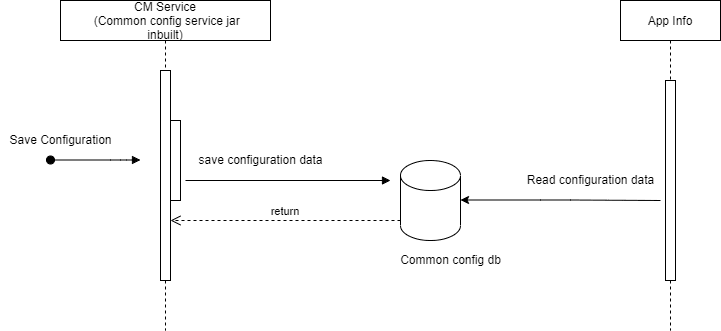
Figure 3-51 Call flow to Get the NF Score
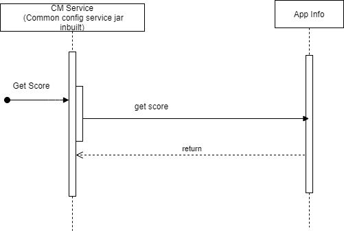
The operator sends a request to CM service to get the score. CM service requests it to App-Info. App-Info queries and calculates NF_Score.
Managing Controlled Shutdown of an instance
Enable
You can enable this feature by selecting the Enable NF Scoring field in the Settings page of NF Scoring.
For more information about enabling the feature through CNC Console, see NF Scoring Configurations.
Configure
Note:
You can configure the env variable, <NF_SCORING_INTERVAL>, in deployment of app-info. Default value is 30 seconds (changing the env variable would result into restart of app-info pod).Observe
Metrics
- nfscore
- nfScoringFactorActualValue
For more information, see AppInfo Metrics .
3.42 NRF Client Retry and Health Check
With the alternate route retry feature, Policy can attempt service requests to an alternate secondary Network Repository Function (NRF) when the primary NRF throws errors. In addition, the health status check feature actively monitors the health of the NRFs and provides the list of the healthy NRFs for session requests only. The NRF client also provides the health information of NRFs to other services if requested, and notifies any change in the health status.
For a given service request, the NRF client initiates a request towards a
healthy and the highest priority NRF. If the NRF client receives a failure response for
the request or the request timed-out, it attempts to send the request to the same NRF
for NrfRetryConfig.primaryNrfRetryCount number of times. If a success
response is received before the retry count gets exhausted, NRF client accepts the
response and does not send any further service requests. However, if NRF client fails to
receive a success response, it attempts to send the service request to an alternate NRF.
The alternate NRF is selected based on the assigned priority and health status.
If the NRF Client receives a retryAfterTime value in the
response header from the NRF, the NRF Client halts any further attempts to the NRF and
flags the NRF as unhealthy for the specified time period. The NRF client retries the
service request to alternate NRFs until any one of the following conditions are met:
- NRF-client receives a success response.
- NrfRetryConfig.alternateNRFRetryCount is exhausted.
- All attempts to available healthy NRFs are exhausted.
Once any of the listed conditions are met, NRF-client accepts the response and proceed.
- If the NRF Client receives a retryAfterTime value in the response header from the NRF, then NRF will be unhealthy for a time period as defined in retryAfterTime.
- If the status code received is available in the default values for
errorCodeReasonsForFailure, then NRF will be
unhealthy for a period of time as defined in
ConfigMap.data:
                        profile.retryAfterTime
. - If the status code received is available in the default values for errorCodeReasonsForFailure and all the retry attempts are exhausted.
- If NRF Client receives an error from Gateway service and the error is configured in the gatewayErrorCodes with all the exhausted retry attempts.
Note:
- If NRF Client receives an error from Gateway service and the error is not configured in the gatewayErrorCodes, then NRF remains marked as healthy.
- HealthCheckConfig and NRFRetryConfig must be configured for the NRF Client functionality to work as expected.
- NRF Client considers a response as failure only when it is
configured in the
errorReasonsForFailureparameter in the custom-values.yaml file. The primary and non-primary NRFs must be geo-redundant for the NRF Retry mechanism to work. - For autonomous procedures such as NfRegistration and
NfHeartbeat, NRF-client continues to retry sending service requests till a
success response is received.
For details on NRF Client configuration parameters, see NRF Client Configuration section in Oracle Communications Cloud Native Core, Converged Binding Support Function Installation, Upgrade and Fault Recovery Guide.
3.43 BSF Message Feed for Monitoring
In order to enable correlation of the internal and external (request/response) messages for all the transactions initiated by the producer and consumer NFs, BSF supports copying the messages at Ingress and Egress Gateways.
This feature allows NFs using Ingress and Egress Gateways to report every incoming and outgoing message to Oracle Communications Network Analytics Data Director (OCNADD) monitoring system.
That is, OCNADD is a message store to keep a copy of each request and response processed through IGW & EGW.
- Call Tracing / Tracking
- Live debugging
Architecture
Figure 3-52 BSF Message Feed Architecture
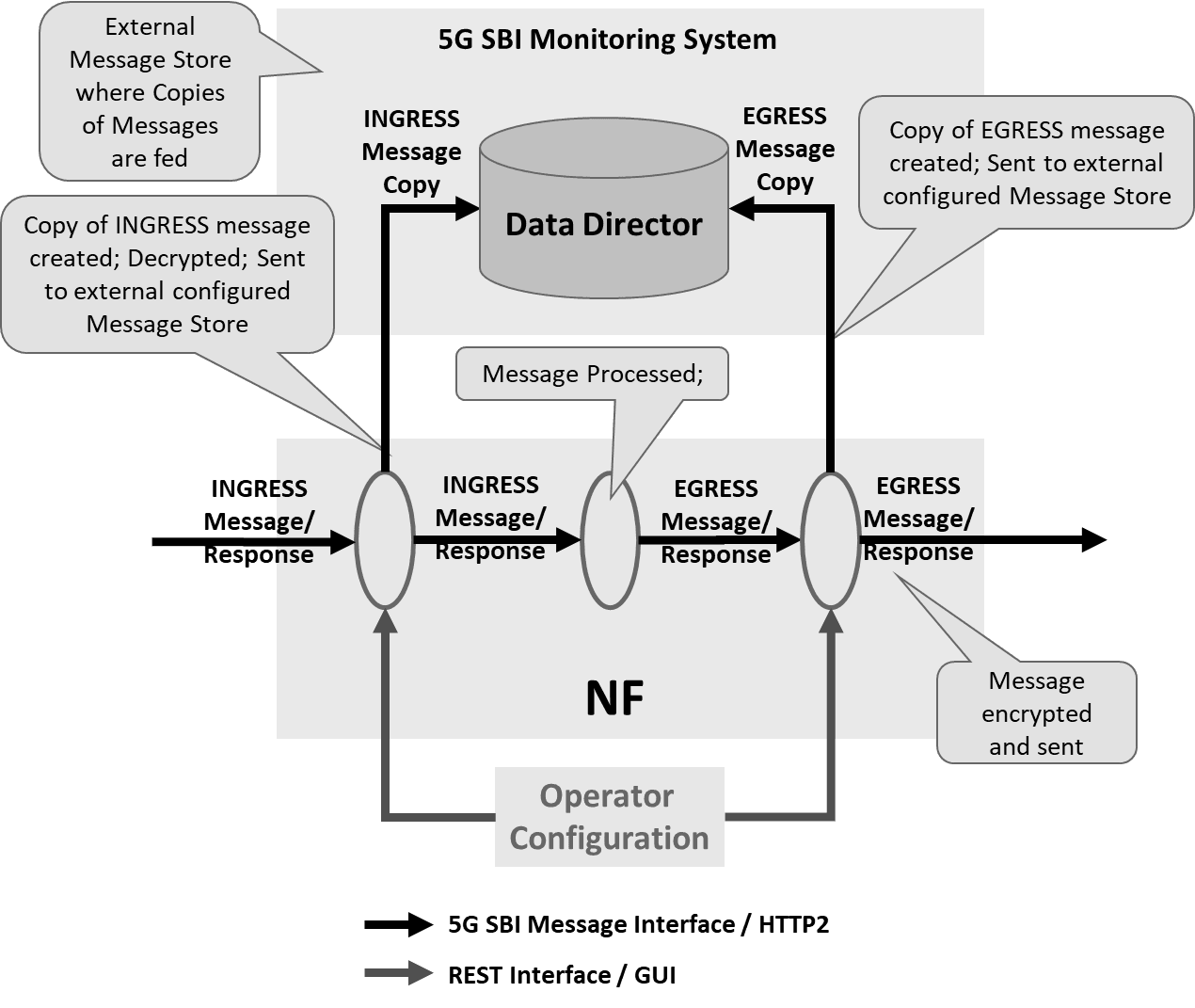
OCNADD is a Network Data Broker part of the Network Analytics suite of products. OCNADD receives network data traffic information from various sources such as 5G NFs and Non-5G Nodes and sends the data securely to subscribed consumer (3rd Party tools) after applying its powerful and configurable filtering, replication, and aggregation rule corresponding to subscribed consumers. For more information on OCNADD, see Oracle Communications Network Analytics Data Director User Guide.
5G NF Kafka Producer is used as the source to send the data stream towards OCNADD. The 5G NFs use integrated Kafka producer services to stream the 5G South Bound Interface (SBI) messages along with metadata added by NFs to OCNADD.
Managing BSF Message Feed
Enable
BSF Message Feed feature can be enabled using Helm parameters either at the time of BSF installation or during the software upgrade.
ingress-gateway.message-copy.enabled parameter is used to enable
copying messages passing through Ingress Gateway.
egress-gateway.message-copy.enabled parameter is used to enable
copying messages passing through Egress Gateway.
For more information, see Configuring Ingress Gateway, Configuring Egress Gateway, and Configuring Kafka for NF Message Feed sections in Oracle Communications Cloud Native Core, Binding Support Function Installation, Upgrade, and Fault Recovery Guide.
Configure
BSF Message Feed feature can be configured using Helm parameters either at the time of BSF installation or during the software upgrade.
For more information, see Configuring Ingress Gateway, Configuring Egress Gateway, and Configuring Kafka for NF Message Feed sections in Oracle Communications Cloud Native Core, Binding Support Function Installation, Upgrade, and Fault Recovery Guide.
SASL_SSL Configuration for BSF Message Copy
As there is no certificate-based client authentication required, a trustStore is created at BSF.
BSF contains placeholders to accept caroot certificates, which are then translated into trustStore using Gateway init-containers.
BSF uses native SSL functionality provided by Gateway services. SSL service block
gets activated or used, when enableIncomingHttps is set to
true. The same configuration is used for message copy SSL
configuration too.
To configure only BSF-DD SSL communication without native SSL functionality, configure caBundle and trustStorePassword sections with appropriate secret configurations.
To use both native SSL functionality and BSF-DD SSL communication, add the caRoot certificate of Kafka broker to the existing caRoot certificate by appending Kafka broker ca certificate after the existing certificate.
- Generate SSL certificates.
Note:
Creation process for private keys, certificates and passwords is based on discretion of user or operator. - Before copying the certificates to the secret, add the DD Root certificates
contents into the CA certificate(caroot.cer) generated for
NRF.
Note:
Make sure to add 8 hyphens "-" between 2 certificates.-----BEGIN CERTIFICATE----- <existing caroot-certificate content> -----END CERTIFICATE----- -------- -----BEGIN CERTIFICATE----- <DD caroot-certificate content> -----END CERTIFICATE----- - Create a secret for authentication with DD.
To create a secret store the password in a text file and use the same file to create a new secret.
kubectl create secret generic ocingress-secret --from-file=ssl_ecdsa_private_key.pem --from-file=rsa_private_key_pkcs1.pem --from-file=ssl_truststore.txt --from-file=ssl_keystore.txt --from-file=caroot.cer --from-file=ssl_rsa_certificate.crt --from-file=ssl_ecdsa_certificate.crt --from-file=sasl.txt -n <namespace> kubectl create secret generic ocegress-secret --from-file=ssl_ecdsa_private_key.pem --from-file=ssl_rsa_private_key.pem --from-file=ssl_truststore.txt --from-file=ssl_keystore.txt --from-file=ssl_cabundle.crt --from-file=ssl_rsa_certificate.crt --from-file=ssl_ecdsa_certificate.crt --from-file=sasl.txt -n <namespace> - Provide appropriate values for the SSL section.
SSL configuration:
service: ssl: privateKey: k8SecretName: ocegress-secret k8NameSpace: bsf rsa: fileName: rsa_private_key_pkcs1.pem ecdsa: fileName: ssl_ecdsa_private_key.pem certificate: k8SecretName: ocegress-secret k8NameSpace: bsf rsa: fileName: tmp.cer ecdsa: fileName: ssl_ecdsa_certificate.crt caBundle: k8SecretName: ocegress-secret k8NameSpace: bsf fileName: caroot.cer keyStorePassword: k8SecretName: ocegress-secret k8NameSpace: bsf fileName: key.txt trustStorePassword: k8SecretName: ocegress-secret k8NameSpace: bsf fileName: trust.txt initialAlgorithm: RS256 - Configure the message copy
feature.
messageCopy: enabled: true copyPayload: true topicName: BSF ackRequired: false retryOnFailure: 0 security: enabled: true protocol: SASL_SSL tlsVersion: TLSv1.2 saslConfiguration: userName: ocnadd password: k8SecretName: ocegress-secret k8NameSpace: bsf fileName: sasl.txt - Make sure to configure the correct SASL_SSL port in
kafka.bootstrapAddressattribute. To get the correct value of this, refer to DD Kafka's Values.yaml file.
Observability
Metrics
- oc_ingressgateway_msgcopy_requests_total
- oc_ingressgateway_msgcopy_responses_total
- oc_egressgateway_msgcopy_requests_total
- oc_egressgateway_msgcopy_responses_total
Alerts
- INGRESS_GATEWAY_DD_UNREACHABLE_MAJOR
- EGRESS_GATEWAY_DD_UNREACHABLE_MAJOR
3.44 Optimizing Lookup in BSF Management Service Database
BSF supports optimized storage and lookup of PCF binding information in BSF Management Service.
BSF stores binding information in the pcf_binding_v2 table and maintains dedicated lookup tables for IPv4 address, IPv6 prefix, and MAC address identifiers. During DISCOVERY operations, BSF can use these lookup tables and primary-key reads to identify the corresponding PCF binding record. If a lookup cannot be resolved through the new tables, BSF can fall back to legacy index-based lookup.
The supported lookup identifiers are IPv4 address, IPv6 prefix, and MAC address. These identifiers may be used with additional discovery attributes, such as SUPI, GPSI, DNN, IP domain, S-NSSAI, or site ID, depending on the discovery request.
During installation or upgrade, BSF creates the pcf_binding_v2 table and the associated IPv4, IPv6, and MAC lookup tables. The json_content column is stored as VARCHAR(12000) and the binding_id column is stored as VARCHAR(128) in the pcf_binding_v2 table.
When migration is enabled, REGISTER operations write new binding records to the pcf_binding_v2 table. Existing binding records are migrated using a lazy migration approach. Eligible legacy records are migrated during Audit processing.
BSF uses a binding identifier format that contains table information used to determine the target table for lookup operations. New records created in the pcf_binding_v2 table use a v2-prefixed binding identifier. Existing records remain available throughout the migration process.
BSF retains the existing pcf_binding table during migration and supports fallback lookup behavior during the transition period. Legacy and migrated records can coexist until migration is complete.
The pcf_binding table must not be deprecated until migration is complete and the table contains no binding records. After all binding records are migrated and lookup is configured to use only the pcf_binding_v2 table, the original pcf_binding table is expected to contain zero records and can be deprecated.
For High Availability (HA) or Geo Redundancy (GR) deployments, feature configuration must be consistent across all sites. If the feature is enabled on some sites but not others, BSF may reject requests during the transition period because different sites may use different binding identifier formats.
This feature updates the binding_id schema to VARCHAR(128). It does not change the external BSF APIs used for PCF binding registration, discovery, or deletion. Request and response formats for Nbsf Management Service procedures remain unchanged.
Migration Procedure for Multi-Site Deployments
The following table describes the recommended migration sequence and corresponding rollback procedure for migrating PCF binding records from LONG BLOB to VARCHAR in a two-site deployment.
Table 3-37 Migration Sequence
| Step | Action | Rollback Procedure | Side Effects |
|---|---|---|---|
| 1 | Upgrade site1 to 26.1.201. | Software rollback on site1. | - |
| 2 | Upgrade site2 to 26.1.201. | Rollback site1 and site2. | - |
| 3 | Update the PCF_BINDING_TABLE_LOOKUP advanced setting to 1 on site1 or site2.
|
Rollback site1 and site2. | - |
| 4 | Update the PCF_BINDING_TABLE_LOOKUP advanced setting to 1 on the other site.
|
Rollback site1 and site2. | - |
| 5 | Set the ENABLE_PCF_BINDING_TABLE_MIGRATION advanced setting to true on site1 or site2.
|
Rollback site1 and site2. | Loss of bindings in the pcf_binding_v2 table.
|
| 6 | Set the ENABLE_PCF_BINDING_TABLE_MIGRATION advanced setting to true on the other site.
|
Rollback site1 and site2. | Loss of bindings in the pcf_binding_v2 table.
|
| 7 | Set the PCF_BINDING_TABLE_LOOKUP advanced setting to 2 on site1 or site2.
|
Rollback site1 and site2. | Loss of bindings in the pcf_binding_v2 table.
|
| 8 | Set the PCF_BINDING_TABLE_LOOKUP advanced setting to 2 on the other site.
|
Rollback site1 and site2. | Loss of bindings in the pcf_binding_v2 table.
|
| 9 | After migration is complete on a site, set the PCF_BINDING_TABLE_LOOKUP advanced setting to 3 on that site.
|
Rollback site1 and site2. | Loss of bindings in the pcf_binding_v2 table.
|
| 10 | After migration is complete on the other site, perform the action described in step 9. | - | - |
Table 3-38 High Availability and Geo Redundancy Behavior During Binding Table Migration
PCF_BINDING_TABLE_LOOKUP value set in both sites
|
Site1, upgraded to 26.1.201: CRUD behavior | Site2, upgraded to 26.1.201: CRUD behavior | Comments | Conclusion |
|---|---|---|---|---|
1 - PCF_BINDING_FIRST |
Reads from the pcf_binding table first, then falls back to the pcf_binding_v2 table. Creates or updates records in the pcf_binding_v2 table when migration is enabled.
|
Reads from the pcf_binding table first, then falls back to the pcf_binding_v2 table. Creates or updates records in the pcf_binding_v2 table when migration is enabled.
|
Initial migration state. Most records are still available in the pcf_binding table.
|
Recommended when 0% to 50% of data is migrated. |
1 - PCF_BINDING_FIRST |
Reads old records from the pcf_binding table first. Migrated or new records are still available through fallback to the pcf_binding_v2 table.
|
Reads old records from the pcf_binding table first. Migrated or new records are still available through fallback to the pcf_binding_v2 table.
|
Safe while migration is progressing and both old and new records exist. | Supported during migration. Move to value 2 after more than 50% of data is migrated.
|
1 - PCF_BINDING_FIRST |
Continues checking the pcf_binding table first, even when most or all records may already be available in the pcf_binding_v2 table.
|
Continues checking the pcf_binding table first, even when most or all records may already be available in the pcf_binding_v2 table.
|
Functional, but less optimal because lookup checks the old table first. | Not recommended after more than 50% of data is migrated. Use value 2 instead.
|
| At this point, the feature will be enabled (ENABLE_PCF_BINDING_TABLE_MIGRATION= true) at both sites. | ||||
2 - PCF_BINDING_V2_FIRST |
Reads from the pcf_binding_v2 table first, then falls back to the pcf_binding table. Creates or updates records in the pcf_binding_v2 table when migration is enabled.
|
Reads from the pcf_binding_v2 table first, then falls back to the pcf_binding table. Creates or updates records in the pcf_binding_v2 table when migration is enabled.
|
Optimized for later migration stages while still allowing fallback to records that remain in the old table. | Recommended when more than 50% but less than 100% of data is migrated. |
3 - PCF_BINDING_V2_ONLY |
Uses only the pcf_binding_v2 table and lookup tables. No fallback to the pcf_binding table.
|
Uses only the pcf_binding_v2 table and lookup tables. No fallback to the pcf_binding table.
|
Use only after migration is complete on both HA/GR sites. | Recommended only when 100% of data is migrated. |
0 - PCF_BINDING_ONLY |
Uses only the pcf_binding table.
|
Uses only the pcf_binding table.
|
Optimized lookup and migration are not used. | Use only before migration starts or if optimized lookup is disabled. |
Note:
Both HA/GR sites must use the samePCF_BINDING_TABLE_LOOKUP value. Use value 1 while migration is starting or still below 50%. Use value 2 after more than 50% of data is migrated. Use value 3 only after 100% of data is migrated on both sites.
Recommendation to Speed Up Migration
During a maintenance window, the operator can use the audit service to speed up migration of records from the pcf_binding table to the pcf_binding_v2 table and the lookup tables.
- Set
Query to PCFtofalse. - Reduce the
maxTTLvalue to enable faster audit of records. - Increase the notification rate so that a larger number of records are sent for audit.
- At the end of the maintenance window, restore the original
maxTTLand notification rate values.
Note:
IfQuery to PCF is not set to false, BSF may send many unnecessary BSF-to-PCF audit requests that are required only for migration.
When the minor alert BSF_PCF_BINDING_TABLE_MIGRATED_PERCENTAGE is triggered, the operator must update the PCF_BINDING_TABLE_LOOKUP value to 3 in the advancedSettings configuration.
After the migration is complete, the operator can optionally delete the pcf_binding table from the database. Before deleting the table, perform the following steps:
- Verify that the
pcf_bindingtable is empty. - If audit is enabled, disable audit and then re-enable it using the GUI or REST API.
- Manually drop the
pcf_bindingtable from the database.
Call Flow Models
Register
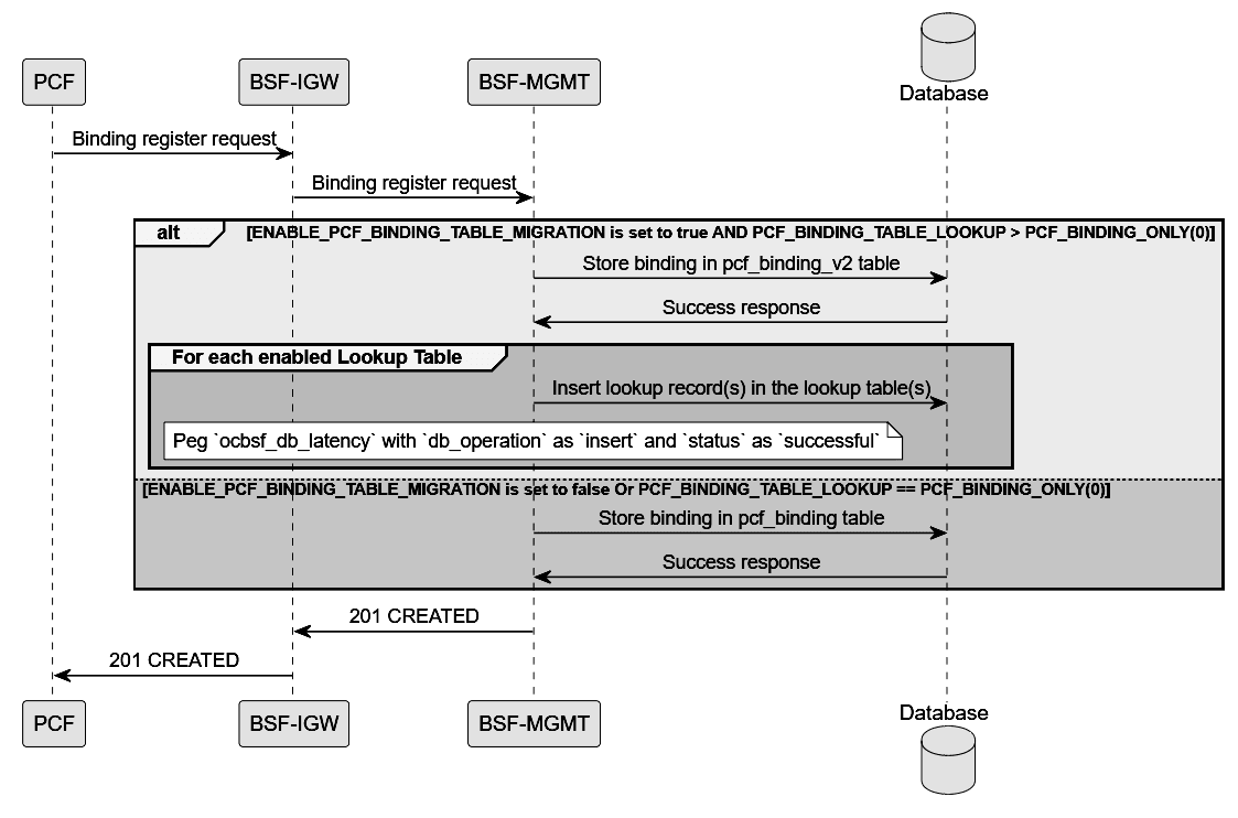
- The PCF sends a Binding register request to the BSF Ingress Gateway.
- The BSF Ingress Gateway forwards the Binding register request to BSF Management.
- BSF Management evaluates the configured binding table migration settings.
- If ENABLE_PCF_BINDING_TABLE_MIGRATION is set to true and PCF_BINDING_TABLE_LOOKUP is set to a value greater than PCF_BINDING_ONLY(0), BSF Management inserts the binding record into the pcf_binding_v2 table.
- The database returns a success response to BSF Management after the binding record is stored.
- For each enabled lookup table, BSF Management inserts the corresponding lookup record or records into the lookup table. These records are populated using the identifier information available in the registered PCF binding.\
- BSF Management pegs the ocbsf_db_latency metric with db_operation set to insert and status set to successful.
- If ENABLE_PCF_BINDING_TABLE_MIGRATION is set to false, or if PCF_BINDING_TABLE_LOOKUP is set to PCF_BINDING_ONLY(0), BSF Management inserts the binding record into the pcf_binding table instead.
- The database returns a success response to BSF Management after the binding record is stored.
- After the binding registration operation is complete, BSF Management returns a 201 CREATED response to the BSF Ingress Gateway.
- The BSF Ingress Gateway forwards the 201 CREATED response to the PCF.
Note:
Insertion into alternate lookup tables can fail. In such cases, the audit process handles reinsertion of any missing lookup records.Note:
The following diagrams are part of a single call flow which has been divided into separate sections.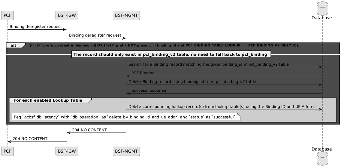
- The PCF sends a Binding deregister request to the BSF Ingress Gateway.
- The BSF Ingress Gateway forwards the Binding deregister request to BSF Management.
- BSF Management evaluates the deregister request against the following condition:
("v2-" prefix present in binding_id) OR ("v2-" prefix NOT present in binding_id and PCF_BINDING_TABLE_LOOKUP == PCF_BINDING_V2_ONLY(3)) - When this condition is met, the binding record is expected to exist only in the pcf_binding_v2 table. BSF Management does not fall back to the pcf_binding table.
- BSF Management searches the pcf_binding_v2 table for a binding record that matches the given binding_id.
- The database returns the matching PCF binding record to BSF Management.
- BSF Management deletes the binding record from the pcf_binding_v2 table using the binding_id.
- The database returns a success response after the binding record is deleted.
- For each enabled lookup table, BSF Management deletes the corresponding lookup records using the Binding ID and UE address.
- BSF Management pegs the ocbsf_db_latency metric with db_operation set to delete_by_binding_id_and_ue_addr and status set to successful.
- BSF Management returns 204 NO CONTENT to the BSF Ingress Gateway.
- The BSF Ingress Gateway forwards the 204 NO CONTENT response to the PCF.
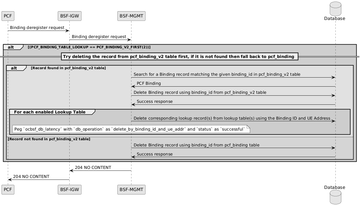
- The PCF sends a Binding deregister request to the BSF Ingress Gateway.
- The BSF Ingress Gateway forwards the Binding deregister request to BSF Management.
- BSF Management evaluates the deregister request against the following condition:
PCF_BINDING_TABLE_LOOKUP == PCF_BINDING_V2_FIRST(2) - When this condition is met, BSF Management first attempts to delete the binding record from the pcf_binding_v2 table.
- BSF Management searches the pcf_binding_v2 table for a binding record that matches the given binding_id.
- If the binding record is found in the pcf_binding_v2 table, the database returns the matching PCF binding to BSF Management.
- BSF Management deletes the binding record from the pcf_binding_v2 table using the binding_id.
- The database returns a success response after the binding record is deleted.
- For each enabled lookup table, BSF Management deletes the corresponding lookup records using the Binding ID and UE address.
- BSF Management pegs the ocbsf_db_latency metric with db_operation set to delete_by_binding_id_and_ue_addr and status set to successful.
- If the binding record is not found in the pcf_binding_v2 table, BSF Management falls back to the pcf_binding table.
- BSF Management deletes the binding record from the pcf_binding table using the binding_id.
- The database returns a success response after the binding record is deleted from the pcf_binding table.
- BSF Management returns 204 NO CONTENT to the BSF Ingress Gateway.
- The BSF Ingress Gateway forwards the 204 NO CONTENT response to the PCF.
pcf_binding First
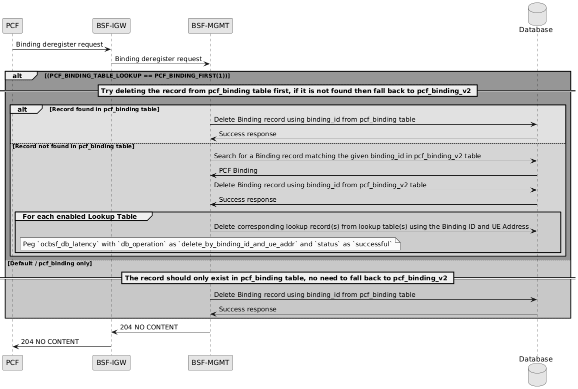
- The PCF sends a Binding deregister request to the BSF Ingress Gateway.
- The BSF Ingress Gateway forwards the Binding deregister request to BSF Management.
- BSF Management evaluates the deregister request against the following condition:
PCF_BINDING_TABLE_LOOKUP == PCF_BINDING_FIRST(1) - When this condition is met, BSF Management first attempts to delete the binding record from the pcf_binding table.
- If the binding record is found in the pcf_binding table, BSF Management deletes the binding record from the pcf_binding table using the binding_id.
- The database returns a success response after the binding record is deleted.
- If the binding record is not found in the pcf_binding table, BSF Management falls back to the pcf_binding_v2 table.
- BSF Management searches the pcf_binding_v2 table for a binding record that matches the given binding_id.
- The database returns the matching PCF binding record to BSF Management.
- BSF Management deletes the binding record from the pcf_binding_v2 table using the binding_id.
- The database returns a success response after the binding record is deleted from the pcf_binding_v2 table.
- For each enabled lookup table, BSF Management deletes the corresponding lookup records using the Binding ID and UE address.
- BSF Management pegs the ocbsf_db_latency metric with db_operation set to delete_by_binding_id_and_ue_addr and status set to successful.
- For the default pcf_binding-only behavior, the record is expected to exist only in the pcf_binding table. BSF Management deletes the binding record from the pcf_binding table and does not fall back to pcf_binding_v2.
- After the delete operation is complete, BSF Management returns 204 NO CONTENT to the BSF Ingress Gateway.
- The BSF Ingress Gateway forwards the 204 NO CONTENT response to the PCF.
Note:
Discovery flows and Rx queries do not perform migration. Migration is handled by the audit process.PCF_BINDING_ONLY (PCF_BINDING_TABLE_LOOKUP == 0)
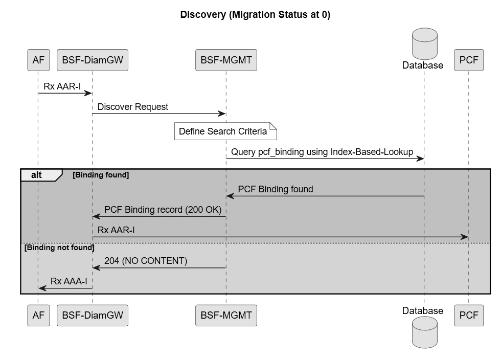
- The AF sends an Rx AAR-I request to the BSF Diameter Gateway.
- The BSF Diameter Gateway sends a Discover Request to BSF Management.
- BSF Management defines the search criteria for the discovery request.
- BSF Management queries the pcf_binding table using index-based lookup.
- If a matching binding record is found, the database returns the PCF binding details to BSF Management.
- BSF Management returns the PCF binding record with a 200 OK response to the BSF Diameter Gateway.
- The BSF Diameter Gateway sends an Rx AAR-I request to the PCF.
- If a matching binding record is not found, BSF Management returns 204 NO CONTENT to the BSF Diameter Gateway.
- The BSF Diameter Gateway returns an Rx AAA-I response to the AF.
PCF_BINDING_FIRST (PCF_BINDING_TABLE_LOOKUP == 1)
Note:
The following diagrams are part of a single call flow which has been divided into separate sections.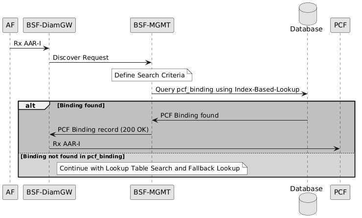
- The AF sends an Rx AAR-I request to the BSF Diameter Gateway.
- The BSF Diameter Gateway sends a Discover Request to BSF Management.
- BSF Management defines the search criteria for the discovery request.
- BSF Management queries the pcf_binding table using index-based lookup.
- If a matching binding record is found in the pcf_binding table, the database returns the PCF binding record to BSF Management.
- BSF Management returns the PCF binding record with 200 OK to the BSF Diameter Gateway.
- The BSF Diameter Gateway forwards the Rx AAR-I request to the PCF.
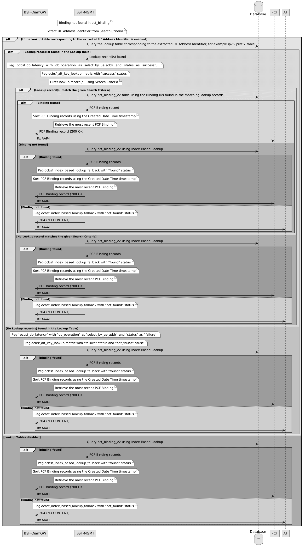
- If no binding record is found in the pcf_binding table, BSF Management extracts the UE address identifier from the search criteria.
- If the lookup table corresponding to the extracted UE address identifier is enabled, BSF Management queries the corresponding lookup table, such as the IPv6 prefix lookup table.
- If lookup records are found, BSF Management pegs the ocbsf_db_latency metric with db_operation set to select_by_ue_addr and status set to successful. It also pegs the ocbsf_alt_key_lookup metric with success status.
- BSF Management filters the lookup records using the search criteria.
- If one or more lookup records match the search criteria, BSF Management queries the pcf_binding_v2 table using the Binding IDs from the matching lookup records.
- If matching PCF binding records are found in the pcf_binding_v2 table, BSF Management sorts the records by the Created Date Time timestamp and retrieves the most recent PCF binding.
- BSF Management returns the PCF binding record with 200 OK to the BSF Diameter Gateway.
- The BSF Diameter Gateway forwards the Rx AAR-I request to the PCF.
- If lookup tables are disabled, no lookup records are found, no lookup records match the search criteria, or no binding record is found using the Binding IDs from the lookup records, BSF Management falls back to index-based lookup in the pcf_binding_v2 table.
- If the fallback lookup finds matching PCF binding records, BSF Management pegs the ocbsf_index_based_lookup_fallback metric with found status.
- BSF Management sorts the returned PCF binding records by the Created Date Time timestamp and retrieves the most recent PCF binding.
- BSF Management returns the PCF binding record with 200 OK to the BSF Diameter Gateway.
- The BSF Diameter Gateway forwards the Rx AAR-I request to the PCF.
- If the fallback lookup does not find a binding record in pcf_binding_v2, BSF Management pegs the ocbsf_index_based_lookup_fallback metric with not_found status.
- BSF Management returns 204 NO CONTENT to the BSF Diameter Gateway.
- The BSF Diameter Gateway returns an Rx AAA-I response to the AF.
PCF_BINDING_V2_FIRST (PCF_BINDING_TABLE_LOOKUP == 2)
Note:
The following diagrams are part of a single call flow which has been divided into separate sections.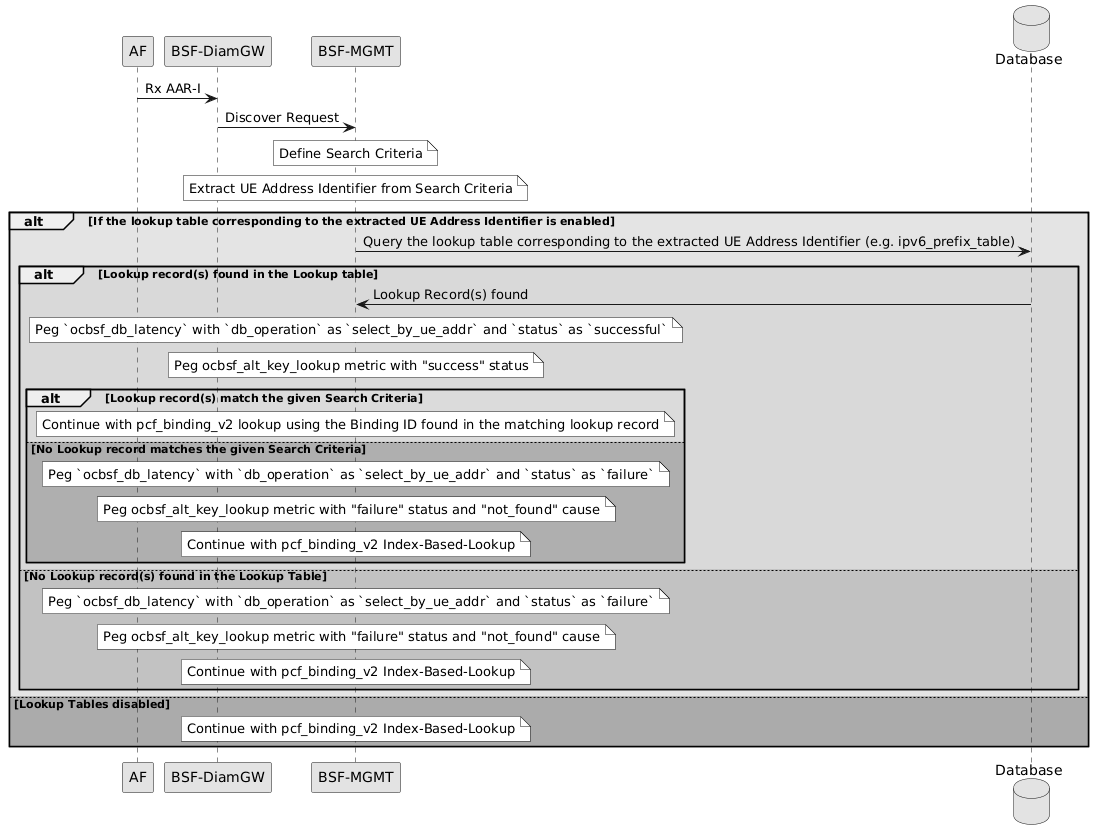
- The AF sends an Rx AAR-I request to the BSF Diameter Gateway.
- The BSF Diameter Gateway sends a Discover Request to BSF Management.
- BSF Management defines the search criteria for the discovery request.
- BSF Management extracts the UE address identifier from the search criteria.
- If the lookup table corresponding to the extracted UE address identifier is enabled, BSF Management queries the corresponding lookup table. For example, if the extracted UE address identifier is an IPv6 prefix, BSF Management queries the IPv6 prefix lookup table.
- If lookup records are found in the lookup table, the database returns the lookup records to BSF Management.
- BSF Management pegs the ocbsf_db_latency metric with db_operation set to select_by_ue_addr and status set to successful.
- BSF Management pegs the ocbsf_alt_key_lookup metric with success status.
- BSF Management checks whether the returned lookup records match the discovery search criteria.
- If the lookup records match the search criteria, the flow continues with pcf_binding_v2 lookup using the Binding ID from the matching lookup record.
- If no lookup record matches the search criteria, BSF Management pegs the ocbsf_db_latency metric with db_operation set to select_by_ue_addr and status set to failure.
- BSF Management pegs the ocbsf_alt_key_lookup metric with failure status and not_found cause.
- The flow continues with index-based lookup in the pcf_binding_v2 table.
- If no lookup records are found in the lookup table, BSF Management pegs the same failure metrics and continues with index-based lookup in the pcf_binding_v2 table.
- If lookup tables are disabled, BSF Management skips lookup-table processing and continues with index-based lookup in the pcf_binding_v2 table.
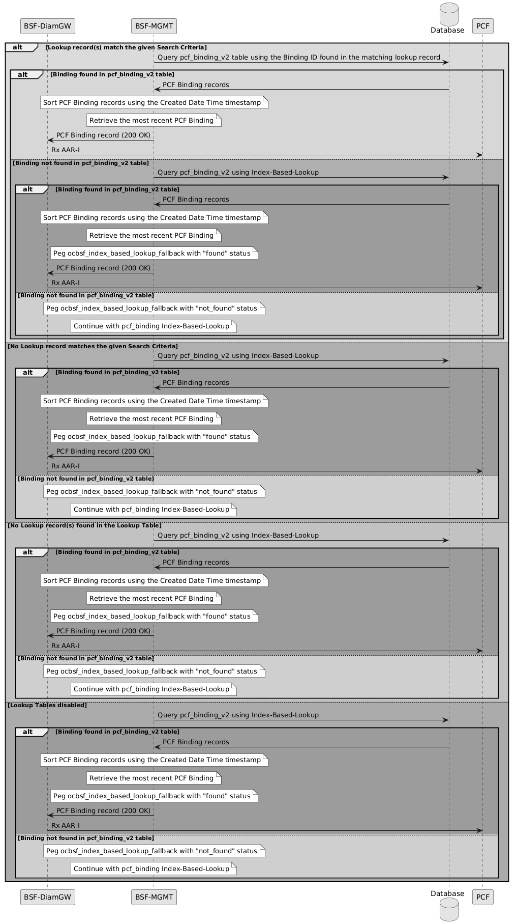
- If a lookup record matches the search criteria, BSF Management queries the pcf_binding_v2 table using the Binding ID from the matching lookup record.
- If a binding is found in the pcf_binding_v2 table, the database returns the PCF binding records to BSF Management.
- BSF Management sorts the PCF binding records using the Created Date Time timestamp.
- BSF Management retrieves the most recent PCF binding.
- BSF Management returns the PCF binding record with 200 OK to the BSF Diameter Gateway.
- The BSF Diameter Gateway forwards the Rx AAR-I request to the PCF.
- If no binding is found in the pcf_binding_v2 table using the Binding ID from the matching lookup record, BSF Management queries the pcf_binding_v2 table using index-based lookup.
- If the index-based lookup finds a binding in the pcf_binding_v2 table, the database returns the PCF binding records to BSF Management.
- BSF Management sorts the PCF binding records using the Created Date Time timestamp.
- BSF Management retrieves the most recent PCF binding.
- BSF Management pegs the ocbsf_index_based_lookup_fallback metric with found status.
- BSF Management returns the PCF binding record with 200 OK to the BSF Diameter Gateway.
- The BSF Diameter Gateway forwards the Rx AAR-I request to the PCF.
- If no binding is found in the pcf_binding_v2 table through index-based lookup, BSF Management pegs the ocbsf_index_based_lookup_fallback metric with not_found status.
- The flow continues with fallback lookup in the pcf_binding table.
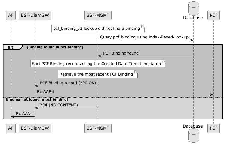
- If the pcf_binding_v2 lookup does not return a binding, BSF Management queries the pcf_binding table using index-based lookup.
- If a binding is found in the pcf_binding table, the database returns the PCF binding to BSF Management.
- BSF Management sorts the PCF binding records using the Created Date Time timestamp, when multiple records are returned.
- BSF Management retrieves the most recent PCF binding.
- BSF Management returns the PCF binding record with 200 OK to the BSF Diameter Gateway.
- The BSF Diameter Gateway forwards the Rx AAR-I request to the PCF.
- If no binding is found in the pcf_binding table, BSF Management returns 204 NO CONTENT to the BSF Diameter Gateway.
- The BSF Diameter Gateway returns an Rx AAA-I response to the AF.
PCF_BINDING_V2_ONLY (PCF_BINDING_TABLE_LOOKUP == 3)
Note:
The following diagrams are part of a single call flow which has been divided into separate sections.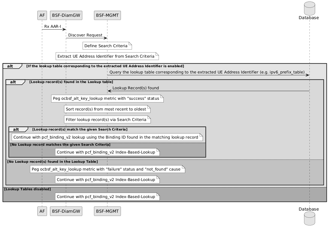
- The AF sends an Rx AAR-I request to the BSF Diameter Gateway.
- The BSF Diameter Gateway sends a Discover Request to BSF Management.
- BSF Management defines the search criteria for the discovery request.
- BSF Management extracts the UE address identifier from the search criteria.
- If the lookup table corresponding to the extracted UE address identifier is enabled, BSF Management queries the corresponding lookup table, such as the ipv6_prefix_table.
- If lookup records are found in the lookup table, the database returns the lookup records to BSF Management.
- BSF Management pegs the ocbsf_alt_key_lookup metric with success status.
- BSF Management sorts the lookup records from most recent to oldest.
- BSF Management filters the lookup records using the search criteria.
- If one or more lookup records match the search criteria, the flow continues with a pcf_binding_v2 lookup using the Binding ID from the matching lookup record.
- If no lookup record matches the search criteria, the flow continues with index-based lookup in the pcf_binding_v2 table.
- If no lookup records are found in the lookup table, BSF Management pegs the ocbsf_alt_key_lookup metric with failure status and not_found cause.
- The flow continues with index-based lookup in the pcf_binding_v2 table.
- If lookup tables are disabled, BSF Management skips lookup-table processing and continues with index-based lookup in the pcf_binding_v2 table.
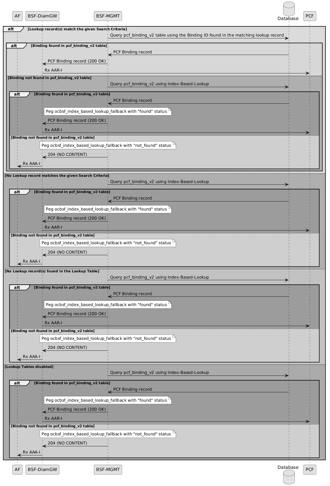
- If a lookup record matches the search criteria, BSF Management queries the pcf_binding_v2 table using the Binding ID from the matching lookup record.
- If a binding is found in the pcf_binding_v2 table, the database returns the PCF binding record to BSF Management.
- BSF Management returns the PCF binding record with 200 OK to the BSF Diameter Gateway.
- The BSF Diameter Gateway forwards the Rx AAR-I request to the PCF.
- If no binding is found in pcf_binding_v2 using the Binding ID from the lookup record, BSF Management queries pcf_binding_v2 using index-based lookup.
- If index-based lookup finds a binding in pcf_binding_v2, the database returns the PCF binding record to BSF Management.
- BSF Management pegs the ocbsf_index_based_lookup_fallback metric with found status.
- BSF Management returns the PCF binding record with 200 OK to the BSF Diameter Gateway.
- The BSF Diameter Gateway forwards the Rx AAR-I request to the PCF.
- If index-based lookup does not find a binding in pcf_binding_v2, BSF Management pegs the ocbsf_index_based_lookup_fallback metric with not_found status.
- BSF Management returns 204 NO CONTENT to the BSF Diameter Gateway.
- The BSF Diameter Gateway returns an Rx AAA-I response to the AF.
Upgrade and Rollback Impact
- Upon upgrade from an earlier BSF release, the
pcf_binding_v2table and the three supported lookup tables are created, and BSF can use the configurations associated with this feature.Note: Data migration does not occur during upgrade. Binding records are migrated through lazy migration using the Audit mechanism.
-
When adding a new site, users performing a bulk import to configure the system must verify that the following BSF service Advanced Settings are configured before running traffic:
- ENABLE_PCF_BINDING_TABLE_MIGRATION=true
- PCF_BINDING_TABLE_LOOKUP=3
Rollback:
Upon rollback from the current BSF release, the new tables are removed and BSF can no longer use the configurations associated with this feature.
Note: If the rollback target BSF release does not support alternate lookup tables, entries in those tables must be cleaned up manually. Binding records stored only in the updated binding table are not retained after rollback to an earlier release.
Managing the Support for Optimizing Lookup in BSF Management Service Database
Enable
Support for Optimizing Lookup in BSF Management Service Database can be enabled using CNC Console.
Enable Using CNC Console
Enable the Enable field the Alternate Lookup Table Audit Settings section on the Management Service page under Service Configurations on CNC Console. For more information, see Management Service.
Configure
Support for Optimizing Lookup in BSF Management Service Database can be configured using CNC Console.
Configure Using CNC Console
Configure the following fields under Alternate Lookup Table Audit Settings section on the Management Service page for Service Configurations on CNC console:
- Minimum Time to Live (in minutes)
- Maximum Time to Live (in minutes)
- Notification Rate (per second)
- Minimum Audit Passes Interval (in minutes)
For more information, see Management Service.
Configure using Custom Values and Deployment YAML
Percentiles of Latency metrics can be configured using Custom Values and Deployment YAML. For more information, see Configuring Database Indexing in Binding Support Function Installation, Upgrade, and Fault Recovery Guide.
The following BSF Management Service metrics are used for this feature:
- ocbsf_feature_incompatibility
- ocbsf_binding_record_lookup_latency
- ocbsf_binding_table_lookup_total
- ocbsf_binding_query_processing_latency
- ocbsf_alt_key_lookup_total
- ocbsf_index_based_lookup_fallback_total
- ocbsf_lookup_table_reinsertions_total
- ocbsf_lookup_table_stale_deletions_total
- ocbsf_db_latency_seconds_count
| DB Operation | Situation |
|---|---|
| insert | Insert operations for Alt Lookup Tables are only expected to happen when:
|
| delete_by_binding_id_and_ue_addr | Delete by Binding ID and UE Addr operations for Alt Lookup Tables are only expected to happen when:
|
| delete_by_binding_id | Delete by Binding ID for Alt Lookup Tables are only expected to happen when:
|
| update_audit_time_by_binding_id_and_ue_addr | Update Audit Time (last_audited_date_time and last_access_timestamp) by Binding ID and UE Addr operations for Alt Lookup Tables are only expected to happen when:
|
| select_by_ue_addr | Select By UE Addr for Alt Lookup Tables are only expected to happen when:
|
| select_by_binding_id_and_ue_addr | Select By Binding ID and UE Addr for Alt Lookup Tables are only expected to happen when:
|
For more information, see BSF Management Service.
Logging
The following are the log entries when a record is migrated.
Note:
- BSF Management must be in the appropriate log level for these logs to appear
- For the sake of simplicity, any object representation will be written as {...} in the below logs.
- DISCOVERY
- A Lookup records matches the given Search Criteria
..., "level": "DEBUG", ..., "message": "Lookup record found for given Search Criteria. lookupRecord: {...}, searchCriteria: {...}", ... - No Lookup record matches the Search Criteria
..., "level": "INFO", ..., "message": "No Lookup records of Lookup Table {...} match the given Search Criteria. Falling back to Index-Based lookup. searchCriteria: {...}", ... - No Lookup records were found on the Lookup Table
..., "level": "INFO", ..., "message": "No Lookup records were found for the Lookup Table {...}. Falling back to Index-Based lookup. searchCriteria: {...}", ...
- A Lookup records matches the given Search Criteria
- REGISTER (including Collision Detection):
- A lookup record has been inserted in a Lookup Table
..., "level": "INFO", ..., "message": "Successfully registered lookup record in Lookup Table {...}. lookupRecord: {...}", ... - A lookup record could not be inserted in a Lookup Table
..., "level": "WARN", ..., "message": "An error occurred while trying to register lookup record in Lookup Table {...}. lookupRecord: {...}, error: {...}", ...
- A lookup record has been inserted in a Lookup Table
- DEREGISTER:
- A lookup record has been deleted in a Lookup Table
..., "level": "INFO", ..., "message": "Successfully deregistered lookup record in Lookup Table {...}. lookupRecord: {...}", ... - A lookup record could not be deleted in a Lookup Table
..., "level": "WARN", ..., "message": "An error occurred while trying to deregister lookup record in Lookup Table {...}. lookupRecord: {...}, error: {...}", ...
- A lookup record has been deleted in a Lookup Table
- AUDIT:
- Audit Notification has been received for a lookup record
..., "level": "DEBUG", ..., "message": "Audit Notification received for lookup record. staleRecordInfo: {...}", ... - Lookup record is already present in lookup table for an audited PCF Binding session
..., "level": "DEBUG", ..., "message": "Lookup record is already present in Lookup Table {...}, no need to register it again. lookupRecord: {...}", ... - Lookup record is not present in lookup table for an audited PCF Binding session
..., "level": "INFO", ..., "message": "No lookup record was found for Binding ID {...} in Lookup Table {...}, will attempt to register it", ... - Lookup record is still an active
..., "level": "DEBUG", ..., "message": "Found an active PCF Binding record for audited lookup record. lookupRecord: {...}, pcfBinding: {...}", ... - Lookup record is stale
..., "level": "INFO", ..., "message": "No active PCF Binding record was found for audited lookup record, proceeding with deletion of stale record. lookupRecord: {...}", ...
- Audit Notification has been received for a lookup record
3.45 Diameter Gateway Connection Repaving
In large Diameter deployments, connection distribution across Diameter Gateway (DGW) pods can become uneven over time due to node restarts, fail overs, scaling operations, or network events. This imbalance can result in some DGW pods handling a disproportionately high number of Diameter connections while others remain underutilized.
Diameter Gateway Connection Repaving feature provides a controlled mechanism to re-balance Diameter connections across the cluster without restarting services or causing a complete outage. It allows to force the disconnection of the existing external Diameter connections so that external peers reconnect through the Layer-4 load balancer and are re-distributed across available Diameter Gateway pods.
- Controlled and staggered disconnection of Diameter connections
- Continuous acceptance of new incoming connections during repaving
- Historical auditing of repaving operations
- Configurable throttling and jitter controls
- Enable/disable control through configuration settings
- Pod-Level Jitter: Prevents all pods from disconnecting simultaneously.
- Connection-Level Throttle: Prevents flooding peers with mass disconnects
- CNC Console
- Diameter Repaving REST API
- The operator, automation client, or CNC Console invokes the Diameter Repaving REST API on CM Service. CM Service validates the request, generates
invocationIdandrequestTimestamp, updates the Config Server trigger topic, and records the trigger in historical_data. Diameter Gateway pods detect the Config Server topic update (common.public.connectionrepaving.diameter-gateway.trigger.disconnect) and executes the repaving operation when the feature is enabled. - Writes an audit entry into the historical_data table.
- Diameter Gateway pods monitor this topic.
- Upon detecting the update, if Enable Diameter Gateway Repaving field is enabled on Diameter Connection Repaving page under Diameter Configuration on CNC Console:
- Each pod calculates a random stagger delay. This prevents simultaneous disconnections across pods.
- After the jitter delay expires, existing external Diameter connections established before the trigger timestamp are disconnected.
The connections are disconnected sequentially.
A configurable delay is applied between disconnect operations.
- New connection requests are continued to be accepted throughout the repaving process, ensuring service continuity.
-
The pod performs the throttled disconnection of connections established before the trigger timestamp. Once disconnections are complete, it marks processing for the trigger as finished and sets
isRepavingBusytofalse. The pod checks its internal queue and returns to idle monitoring when the queue is empty. - External Peers, having their old connections terminated, will automatically attempt to re-establish their connections (if they haven't already done so with new connections accepted during the process).
- These new connection attempts are accepted by the Diameter Gateway pods.
-
Diameter Gateway processing completes after the pod has handled all eligible external Diameter connections established before the trigger timestamp and completed any applicable queued trigger processing. External peers subsequently reconnect, and the Layer-4 load balancer redistributes the new connections. The resulting connection distribution must be verified using external monitoring.
Note:
The Diameter Gateway side repaving completes after eligible connections are disconnected. The final balancing depends on peer re-connection behavior and load balancer distribution.
Call Flows
Figure 3-53 Diameter Gateway Connection Termination
Figure 3-54 Overlapping Repaving Triggers with Queue
Scenario 1: Successful Connection Repaving Execution
-
Initiation (Operator Action & CM Service Update)
A request is sent to the CM Service's dedicated repaving API endpoint (such as
{apiRoot}/oc-bsf-configuration/v1/diameterRepaving/triggerDisconnection).The CM Service validates the request, generates a unique
invocationIdandrequestTimestamp.The CM Service updates the configuration topic (
common.public.connectionrepaving.diameter-gateway) in the Config Server by replacing the trigger information with the latest one, holding the latestinvocationIdandrequestTimestamp.The CM Service logs a single entry to the
historical_datatable withtype="diameterRepavingTrigger", including theinvocationIdandrequestTimestampin the value field. -
Configuration Change Detection (Diameter Gateway Pods)
Each Diameter Gateway pod's configuration client, which is monitoring the
common.public.connectionrepaving.diameter-gateway.trigger.disconnecttopic, detects the update (the newly added entry).The config client invokes the onChange (or equivalent) callback method within the Diameter Gateway service, passing the updated list of invocation records.
-
Two-Tiered Disconnection Execution (Diameter Gateway Pods)
-
Trigger Validation: Inside the onChange handler, each pod:
Retrieves the latest invocation record from the received data.
Compares its
invocationIdwith the ID of the last trigger it processed (stored locally).If the ID is new: Checks if the feature is enabled (
common.public.connectionrepaving.diameter-gateway.config enabled is true) and if the minimum re-invocation delay (DGW_CONNECTION_REPAVING.REINVOCATION_DELAY_MIN) has passed. -
Tier 1 (Pod-Level Jitter): If validation passes, the pod:
Stores the new
invocationIdas the last processed ID.Independently calculates a random stagger delay based on
DGW_CONNECTION_REPAVING.MAX_STAGGER_JITTER_MS.Wait Time = random(0, MAX_STAGGER_JITTER_MS)Pauses execution for this unique, random duration (for example, Pod-A might wait 17 ms, Pod-B might wait 142 ms). Logs that it is waiting.
-
Service Continuity: During this entire process (both the initial wait and the disconnection phase), all Diameter Gateway pods remain active and accepts new incoming connections from peers.
-
Tier 2 (Connection-Level Throttle): After its random pod-level delay expires, the pod begins its disconnection logic.
It iterates through all its existing external Diameter connections that were established before the
requestTimestampassociated with the currentinvocationId.The order of disconnection is not based on load or complex logic.
To prevent flooding the peer, the pod pauses between terminating each connection for the interval specified in
DGW_CONNECTION_REPAVING.CONNECTION_DISCONNECT_INTERVAL_MS.
-
-
Sequential Trigger Processing with Internal Queue: To enhance robustness in scenarios where repaving might be triggered very frequently (potentially faster than a pod's disconnection cycle +
DGW_CONNECTION_REPAVING.REINVOCATION_DELAY_MIN), a queue and theisRepavingBusyflag are implemented In this model:The flag
isRepavingBusydetermines if a given repaving trigger is completed or it is still in progress, changing the status (true/false) when it starts and finishes.Each Diameter Gateway pod maintains an internal queue for incoming repaving triggers (represented by their
invocationIdandrequestTimestamp).When a new trigger is detected using onChange, is added to the queue if the pod is currently busy processing a previous trigger.
Once a pod completes a repaving cycle the
isRepavingBusyflag is set tofalse. It checks its internal queue. If the queue is not empty, it dequeues the next trigger and begins processing it. After validating theDGW_CONNECTION_REPAVING.REINVOCATION_DELAY_MINagainst the dequeued trigger's timestamp relative to the previously completed one.This ensures that the rapid triggers are not lost or rejected but are processed sequentially, preserving the order of operations while still preventing simultaneous execution within a single pod. This approach offers greater resilience against very high trigger rates.
-
Completion and Recovery:
External Peers, having their old connections terminated, automatically attempts to re-establish their connections (if they are not already done so with new connections accepted during the process).
These new connection attempts are accepted by the Diameter Gateway pods.
The new connections are naturally re-balanced across the cluster by the Layer-4 load balancer, completing the repaving process.
Scenario 2: New Connection Attempt During Force Disconnection
This scenario describes what happens when an external system tries to connect while a pod is actively repaving.
- Upon receiving the configuration change event, the Diameter Gateway pod starts the disconnection of all external connections established prior to the timestamp included in the event.
- An external peer sends a new connection request (such as a Diameter CER message) to the Diameter Gateway pod.
- Diameter Gateway pod continues accepting external connections during force disconnections.
- The external peer likely retry the connection after a back off period, by which time the Diameter Gateway pod may have completed its process.
Scenario 3: Diameter Repaving is Triggered While this Feature is Disabled
This scenario covers the safety mechanism provided by the feature flag.
- An API request to the CM Service to trigger Diameter Repaving.
- Configuration topic is updated in config server database.
- The Diameter Gateway configuration watcher detects the configuration change.
- It checks if the feature is enabled based on the value in
common.public.connectionrepaving.diameter-gateway.configtopic and finds that it is set tofalse. - The client ignores the state change and does not execute the diameter repaving.
- The process stops immediately. The Diameter Gateway pods are never notified and continue to operate normally without any interruption.
Scenario 4: Overlapping Repaving Triggers with Queuing
This scenario describes how a Diameter Gateway pod handles a new repaving trigger that arrives while it is already processing a previous one, utilizing an internal queue.
- Initial State: Diameter Gateway Pod-A is idle (not currently repaving) and is monitoring the
common.public.connectionrepaving.diameter-gatewaytopic. Its last processedinvocationIdis null or some older ID. - Trigger 1 Initiation: A repaving request is initiated through the API. The CM Service updates the config topic with
{ "invocationId": "trigger-UUID-1", "requestTimestamp": "T1" }. CM Service logs the trigger inhistorical_data. -
Diameter Gateway Pod-A Detects & Starts Trigger 1:
Pod-A's config client detects the change. The onChange handler runs.
It compares
"trigger-UUID-1"(latest) with its last processed ID (old/null).Feature flag and re-invocation delay check is passed.
Pod-A stores
"trigger-UUID-1"as its last started ID.Pod-A calculates its random jitter delay (such as Jitter-1).
Pod-A enters a
"busy"state (for example, sets an internalisRepavingBusyflag totrue) and begins the Jitter-1 wait period. - Trigger 2 Initiation (During Pod-A's Busy State): Before Pod-A completes its disconnection cycle for Trigger 1 (either during the Jitter-1 wait or the subsequent throttled disconnection phase), the operator triggers repaving again. The CM Service updates the config topic, appending
{ "invocationId": "trigger-UUID-2", "requestTimestamp": "T2" }. CM Service logs this second trigger. -
Diameter Gateway Pod-A detects trigger 2:
Pod-A's config client detects the second change (the list now contains both triggers). The onChange handler runs again.
It compares
"trigger-UUID-2"(latest) with its last started ID ("trigger-UUID-1").It checks its internal state and finds that
isRepavingBusyflag is set totrue.Instead of immediately processing it, Pod-A adds Trigger 2 (
"trigger-UUID-2", T2) to its internal queue. It does not calculate jitter or start waiting for Trigger 2 yet. -
Diameter Gateway Pod-A Completes Trigger 1:
Pod-A finishes the Jitter-1 wait.
It performs the throttled disconnection of connections established before T1.
Once the disconnections for Trigger 1 are complete, it marks processing for
"trigger-UUID-1"as finished and setsisRepavingBusyflag back tofalse. -
Diameter Gateway Pod-A Dequeues & Starts Trigger 2:
Pod-A checks its internal queue and finds Trigger 2. It dequeues it.
It performs the validation checks for Trigger 2:-
Feature flag check.
-
Re-invocation delay check: Compares T2 against the completion time of Trigger 1 using
REINVOCATION_DELAY_MIN. The check is passed.
Pod-A stores
"trigger-UUID-2"as its last started ID.Pod-A calculates its random jitter delay (Jitter-2).
Pod-A sets
isRepavingBusyflag totrueand begins the Jitter-2 wait period. -
-
Diameter Gateway Pod-A Completes Trigger 2:
Pod-A finishes the Jitter-2 wait.
It performs the throttled disconnection of connections established before T2 (but after T1, if any were established and accepted in between).
Once disconnections for Trigger 2 are complete, it marks processing for
"trigger-UUID-2"as finished, setsisRepavingBusyflag tofalse.Pod-A checks its internal queue again; it's empty. The pod returns to idle monitoring.
Managing Diameter Gateway Connection Repaving
Enable
This feature can be enabled using CNC Console and REST API.
Enable Using CNC Console
To enable this feature using CNC Console, enable Enable Diameter Gateway Repaving field on Diameter Connection Repaving page under Diameter Configuration on CNC Console.
For more information, see Diameter Repaving.
Enable Using REST API
To enable this feature using REST API, use Diameter Repaving API.
The URI to access the Diameter Repaving API is {apiRoot}/oc-bsf-configuration/v1/diameterRepaving/config.
Configure
This feature can be configured using CNC Console and REST API.
Configure Using CNC Console
- DGW_CONNECTION_REPAVING.MAX_STAGGER_JITTER_MS
- DGW_CONNECTION_REPAVING.REINVOCATION_DELAY_MIN
- DGW_CONNECTION_REPAVING.CONNECTION_DISCONNECT_INTERVAL_MS
- DGW_CONNECTION_REPAVING.DPR_DELAY_MS
- DGW_CONNECTION_REPAVING.DPR_DISCONNECT_CAUSE
For more information, see Settings.
Configure Using REST API
This feature can be enabled and configured using the Diameter Repaving API.
Use the {apiRoot}/oc-bsf-configuration/v1/diameterRepaving/config to configure the feature.
Use the {apiRoot}/oc-bsf-configuration/v1/diameterRepaving/triggerDisconnection to disconnect the existing external Diameter connections established before the trigger timestamp.
{apiRoot}/oc-bsf-configuration/v1/diameter/settings:
- DGW_CONNECTION_REPAVING.MAX_STAGGER_JITTER_MS
- DGW_CONNECTION_REPAVING.REINVOCATION_DELAY_MIN
- DGW_CONNECTION_REPAVING.CONNECTION_DISCONNECT_INTERVAL_MS
- DGW_CONNECTION_REPAVING.DPR_DELAY_MS
- DGW_CONNECTION_REPAVING.DPR_DISCONNECT_CAUSE
Note:
The default repaving values in these advanced settings keys are likely implicit unless they are overridden.Observability
Metrics
The diam_repaving_disconnections_total metric is to count the total number of connections terminated by the "force disconnect" mechanism. For more information, see Diameter Gateway Metrics.
Note:
- The success of the re-balancing relies on the Layer-4 Load Balancer distributing new connection attempts effectively across the available pods after the disconnections occur. Common load balancing methods like "round robin" or "least connections" are expected to facilitate this re-balancing, assuming external clients promptly attempt to reconnect.
- It is assumed that the external Diameter clients automatically attempt to reconnect following the forced disconnection. The success of the connection repaving relies on this client behavior, even if not all connections are immediately re-established due to varying client load or specific retry logic.
- External monitoring tools, such as KPIs must be used to detect connection imbalance.
- This feature is not autonomous and requires explicit operator intervention to initiate.
- The solution's effectiveness requires the Diameter Gateway pods to be up and running. While it works effectively with direct load balancer-to-pod routing and is expected to work with service meshes like Istio with ASM sidecars (acting as TCP proxies), certain Kubernetes network configurations using kube-proxy might limit the overall re-balancing effectiveness. This is because each kube-proxy instance on different nodes can independently load balance connections across the Diameter Gateway pods, potentially leading to less predictable or less globally optimized connection distribution after the repaving process completes.
- The disconnection action triggers the termination of all existing external inbound connections on each pod, rather than calculating a minimal, targeted number of connections to drop.
3.46 Security Context
The Security Context feature improves the security posture of deployed workloads in Oracle Communications Cloud Native Core, Binding Support Function (BSF), by applying Kubernetes pod and container security context settings.
A security context defines privilege and access-control settings for a pod or container. These settings control how containers run, which user and group IDs are used, whether privilege escalation is allowed, which Linux capabilities are available, and whether the root file system is writable.
This feature applies the SA-approved deployment security-context recommendations to BSF services, Common Services consumed by BSF, and one-click BSF deployment values. The implementation supports the following deployment models:
-
OC-CNE-based deployments.
-
Non-OC-CNE deployments where the customer has no sidecar injections, or sidecars do not require special or elevated privileges.
-
Non-OC-CNE deployments where the customer requires sidecar injections with different or elevated privileges.
binding-servicebulwarkcmserviceconfig-serverdiam-connectordiam-gatewayldap-gatewaynotifiernwdaf-agentpcf-amservicepcf-smservicepcf-ueservicepcf-userservicepcrf-coreperf-infopolicy-runtimepolicydsqueryservicesession-state-auditsoapconnectorusage-monapp_info
enableContainerSecurityContext: true
enablePodSecurityContext: false

podSecurityContext:
  runAsNonRoot: true
  runAsGroup: 25
  runAsUser: 25

containerSecurityContext:
  runAsNonRoot: true
  readOnlyRootFilesystem: true
  allowPrivilegeEscalation: false
  privileged: false
  capabilities:
    drop:
      - ALL
The container security context is enabled by default. The pod security context is available but disabled by default to avoid compatibility issues with deployments that use sidecar containers or other pod-level requirements.
Managing Security Context Feature
Enable
You can enable the Security Context Feature using Helm Configuration:
Enable Container Security Context:
You can enable or disable the feature by setting the enableContainerSecurityContext parameter to true or false in the custom-values.yaml file. The container security context is enabled by default.
Enable Pod Security Context:
You can enable or disable the feature by setting the enablePodSecurityContext parameter to true or false in the custom-values.yaml file. The pod security context is disabled by default.
Service-Specific Configuration:
config-server::
  podSecurityContext:
    runAsNonRoot: true
    runAsUser: 10001
    runAsGroup: 10001
  containerSecurityContext:
    runAsNonRoot: true
    allowPrivilegeEscalation: false
    privileged: false
    readOnlyRootFilesystem: true
    capabilities:
      drop:
        - "ALL"
Deployment Template:
apiVersion: apps/v1
kind: Deployment
metadata:
  ...
spec:
  ...
  template:
    spec:
      ...
      {{- if .Values.global.setHostUsers }}
      hostUsers: false
      {{- end }}
      {{- if .Values.enablePodSecurityContext }}
      securityContext:
        {{- toYaml .Values.podSecurityContext | nindent 8 }}
      {{- end }}
      containers:
        - name: {{ .Chart.Name }}
          ...
          {{- if .Values.enableContainerSecurityContext }}
          securityContext:
            {{- toYaml .Values.containerSecurityContext | nindent 12 }}
          {{- end }}
Observability
There are no new Metrics, KPIs or alerts available for this feature.