3 OCNADD Features
This section explains Oracle Communications Network Analytics Data Director (OCNADD) features.
3.1 Data Governance
OCNADD provides data governance by managing the availability and usability of data in enterprise systems. It also ensures that the integrity and security of the data is maintained by adhering to all the Oracle defined data standards and policies for data usage rules.
3.2 High Availability
OCNADD supports microservice based architecture and OCNADD instances are deployed in Cloud Native Environments (CNEs) which ensure high availability of services and auto scaling based on resource utilization. In the case of pod failures, new service instances are spawned immediately.
In case of K8s cluster failure, the OCNADD deployment is restored to a different cluster using the disaster recovery mechanisms. For more information about the disaster recovery procedures, see Oracle Communications Network Analytics Data Director Installation, Upgrade, and Fault Recovery Guide.
3.3 Data Aggregation
OCNADD performs data aggregation of the network traffic coming from different NFs, such as SCP, SEPP, and NRF. It aggregates the data and provides aggregated traffic feed to the third party consumer applications.
The following diagram shows a high-level architecture of the OCNADD data aggregation feature:
Figure 3-1 Data Aggregation

For information about creating data feeds using CNC Console, see Configuring OCNADD Using CNC Console.
3.4 Data Filtering
OCNADD performs data filtering on messages and enables third-party consumers to gather relevant traffic. The filtering provides the following advantages to consumers:
- Streamlined Troubleshooting: By reducing the volume of traffic, OCNADD facilitates smoother troubleshooting processes.
- Targeted Traffic: Consumers exclusively receive traffic that aligns with their interests.
- Optimized Bandwidth Utilization: OCNADD ensures efficient utilization of the network bandwidth.
OCNADD supports filtering on both Ingress and Egress gateways. It allows to filter packets sent on the N12 interface between AMF and AUSF and N13 interface between AUSF and UDM. The SCP is the data source of traffic (or data) captured between AMF and AUSF. The OCNADD is placed between both the ingress and egress flows therefore filtering can be applied on both the flows, as depicted in the diagram below:
Figure 3-2 Data Filtering

Currently, the OCNADD filtering module offers fundamental metadata filtering for key fields in the metadata list. In the future, this module will be expanded to include advanced filtering capabilities.
- service-name
- user-agent
- consumer-id
- producer-id
- consumer-fqdn
- producer-fqdn
- message-direction
- reroute-cause
- feed-source-nf-type
- feed-source-nf-fqdn
- feed-source-nf-instance-id
- feed-source-pod-instance-id
- consumer-id
- producer-id
- consumer-fqdn
- producer-fqdn
- reroute-cause
- feed-source-nf-type
- feed-source-nf-fqdn
- feed-source-nf-instance-id
- feed-source-pod-instance-id
You can configure data filters (maximum of four filters) through the CNC Console GUI.
However, you can also configure any combination of the filter conditions.
When more than one filter condition is configured, you can define filtering rules using
keywords such as “or” or “and”. For example, consumer-id OR
producer-id. For more information about creating, editing, or
deleting a filter, see Data Filters section in Configuring OCNADD Using CNC Console.
3.5 Synthetic Packet Data Generation
OCNADD converts incoming JSON data into network transfer wire format and sends the converted packets to the third-party monitoring applications in a secure manner. This third-party probe feeds the synthetic packets to the internal monitoring applications. The feature helps third-party vendors to eliminate the need of creating additional applications to receive JSON data and converting the data into probe compatible format, thereby saving critical compute resources and associated costs.
The following diagram shows a high-level architecture of the OCNADD synthetic packet data generation feature:
Figure 3-3 Synthetic Packet Data Generation

3.6 Health Monitoring
OCNADD performs health monitoring to check the readiness and liveness of each OCNADD service and raises alarms in case of service failure.
OCNADD performs the monitoring based on the heartbeat mechanism where each of the OCNADD service instances registers with the Health Monitoring service and exchanges heartbeat with it. If the pod instance goes down, the health monitoring service raises an alarm. Few of the important scenarios when an alarm is raised, are as follows:
- When maximum number of replicas for a service have been instantiated.
- When a service is in down state.
- When CPU or memory threshold is reached.
The health monitoring functionality allows OCNADD to generate health reports of each service on a periodic basis or on demand. You can access the reports through the OCNADD Dashboard. For more information about the dashboard, see OCNADD Dashboard.
The health monitoring service is depicted in the diagram below:
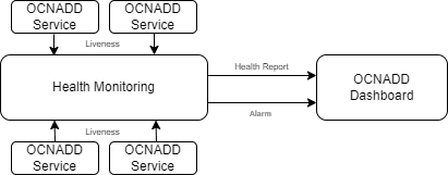
The health monitoring functionality also supports collection of various metrics related to the service resource utilization. It stores them in the metric collection database tables. The health monitoring service generates alarms for the missing heartbeat, connection breakdown, and the exceeding threshold.
3.7 Data Replication
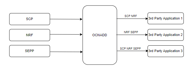
OCNADD allows data replication functionality. The data streams from OCNADD services can be replicated to multiple third party applications simultaneously.
The following diagram depicts OCNADD data replication:
Figure 3-4 Data Replication
3.8 Backup and Restore
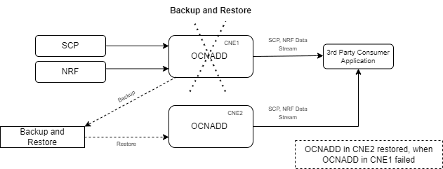
OCNADD supports backup and restore to ensure high availability and quick recovery from failures such as cluster failure, database corruption, and so on. The supported backup methods are automated and manual backups. For more information on backup and restore, see Oracle Communications Network Analytics Data Director Installation, Upgrade, and Fault Recovery Guide.
The following diagram depicts backup and restore supported by OCNADD:
Figure 3-5 Backup and Restore
3.9 Secure Transport
OCNADD provides secure data communication between producer NFs and third party consumer applications. All the incoming and outgoing data streams from OCNADD are TLS encrypted.
The following diagram provides a secure transport by OCNADD:
Figure 3-6 Secure Transport

3.10 Operational Dashboard
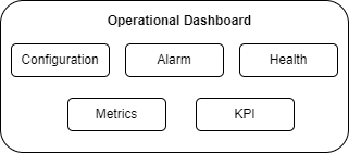
OCNADD provides an operational dashboard which provides a rich visualization of various metrics, KPIs, and alarms.
The dashboard can be depicted as follows:
Figure 3-7 Operational Dashboard
For more information about accessing the dashboard through CNC Console, see OCNADD Dashboard.
3.11 Weighted Load Balancing Based on Correlation ID
OCNADD supports the weighted load balancing of data feeds among the different endpoints of the third-party consumer application. A new load balancing method, "Weighted Load Balancing," is introduced. All incoming messages to the Data Director have a correlation ID. With the introduction of weighted load balancing, the requests and responses having the same correlation ID are delivered to the same destination endpoint. The operator can configure Weighted Load Balancing through the CNC Console GUI. The default load balancing method is "Round Robin." The operator can allocate load factors (in percentage) to each destination endpoint, and the total of the load factors assigned to the destination endpoints must be 100%. By default, load sharing is equally distributed among the endpoints. The maximum number of destination endpoints allowed is two. Weighted load balancing can be applied to HTTP, HTTPS, and Synthetic Packet traffic. In case of an endpoint failure, the Data Director distributes the response to the available endpoints in an equal percentage or as per the configured percentage. At present, only two endpoints are supported. So, any failure in one of the endpoints will result in the complete traffic being sent to the available endpoint.

For information about configuring load balancing using CNC Console, see Configuring OCNADD Using CNC Console
3.12 Support for Multisite Georedundant Deployments
Overview
A network comprises of multiple sites, and each site can be located at different data centers and can be spread across geographic locations. In a georedundant deployment, data is replicated across sites in order to efficiently handle failure scenarios and ensure High Availability (HA). A network failure can occur due to reasons such as network outages, software defects, hardware issues, and so on. These failures impact the continuity of network services. Georedundancy is used to mitigate such network failures and ensure service continuity in a network. In a georedundant deployment, when a failure occurs at one site, an alternate site takes ownership of all the subscriptions and activities of the failed site. The alternate site ensures consistent data flow, service continuity, and minimal performance loss.
Georedundant Deployment Architecture
The OCNADD supports both two site and three site georedundant deployments. The following diagram depicts a two site georedundant deployment:
Figure 3-8 Georedundancy Architecture
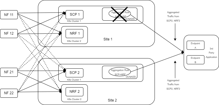
Note:
- Ensure the georedundant sites have sufficient resources to manage the failover traffic from NFs.
- The feed configuration in the redundant sites should be the same.
If any of the georedundant OCNADD sites experience a failure, manual failover procedures must be performed to move NF traffic from the failed site to the available OCNADD site. For information about procedures to route traffic to live OCNADD sites, see Manual Failover in Multisite Georedundant Deployments.
3.13 L3-L4 Information for Synthetic Packet Feed
The OCNADD allows users to configure the L3-L4 mapping rule in the feed and the Global L3-L4 configuration to fetch L3-L4 information when the rule defined in the feed matches the incoming data.
Figure 3-9 Global L3-L4 Configuration
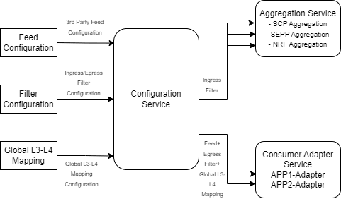
Note:
OCNADD supports GUI-based configuration of L3-L4 information:- For feed level L3L4 configuration using GUI, see Creating Standard Feed and Editing Feed Level L3L4 Configuration.
- For global L3L4 configuration using GUI, see Configuring Global L3L4 Mapping.
Global L3-L4 Mapping Configuration
OCNADD users can configure a list of L3-L4 attribute rules (a combination of rules) by specifying the attribute names and values mapped to IP addresses and port numbers. OCNADD uses these configuration rules that are used to obtain the L3 and L4 address from the global mapping configuration during synthetic packet encoding. Only one Global L3-L4 mapping configuration is applicable to all synthetic feeds.
Table 3-1 Global L3-L4 Configuration
| Attribute 1 | Value | Attribute 2 | Value | IP Address | Port |
|---|---|---|---|---|---|
| L3L4MappintAttributes | String | SuportedL3L4MappingDto | String | String | String |
| consumer-fqdn | 1244 | - | - | 10.10.10.100 | 8080 |
| feed-source-nf-fqdn | <FQDN> | message-direction | RxRequest | 100.100.100.101 | 8181 |
| producer-fqdn | <FQDN> | api-name | nausf-auth | 100.100.100.102 | 8182 |
Note:
- Only two attributes are supported in each row.
- Two attributes in a row are combined with the condition AND during internal processing to identify a match.
- IPv6 is not supported.
- The attribute values are case-sensitive.
- api-name: User must add the api-name taken from
the :path header as value for this attribute in Global L3-L4
configuration.
- nausf-auth or nausf* or *nausf*
formats are supported, and will have the same matching output.
For example: When the api-name is nausf*, the value present in metadata: nausf-auth or nausf-sorprotection or nausf-upuprotection match.
This fulfills the requirement of L3 and L4 mapping when the same AUSF NF is serving all services.
-
nausf*-auth: It is recommended not to add * between
the attribute values for matching, as the condition may or may not
be matched based on value.
For example: When the api-name is nausf*-auth, the value present in metadata: nausf-auth or nausf-sorprotection or nausf-upuprotection, a different value is matched and only the first value matches.
When the api-name is nausf*-test , the value present in metadata: nausf-auth or nausf-sorprotection or nausf-upuprotection a different value is matched and none of the other values match.
- nausf-auth or nausf* or *nausf*
formats are supported, and will have the same matching output.
Feed L3-L4 Mapping Configuration
This configuration allows the user to add L3-L4 mapping rule in the synthetic feed configuration that is verified during synthetic packet encoding to obtain L3-L4 mapping information.
The following table depicts the feed L3-L4 mapping configuration:
Note:
Two mapping rules should be combined only with the operator AND, no other operator is supported.
Table 3-2 Feed L3-L4 Mapping Configuration
| Direction | Address | Mapping Priority | L3-L4 Mapping Rule | Mapping Reference | Least Priority Address | |
|---|---|---|---|---|---|---|
| Supported Values: rxRequest, txRequest, rxResponse. txResponse | Supported Values: source-ip, destination-ip, source-port, destination-port | Default Value: METADATA, Supported Values: METADATA, DD_MAPPING | Default Rule | Recommended Rule | Default Value: DD_MAPPING, Supported Value: DD_MAPPING | Address |
| RxRequest | source-ip | METADATA | consumer-fqdn | consumer-fqdn, consumer-fqdn AND api-name | DD_MAPPING | <IP> |
| destination-ip | METADATA | feed-source-nf-fqdn AND message-direction | DD_MAPPING | <IP> | ||
| source-port | METADATA | feed-source-nf-fqdn | feed-source-nf-fqdn, feed-source-nf-fqdn AND consumer-fqdn | DD_MAPPING | <PORT> | |
| destination-port | METADATA | feed-source-nf-fqdn | DD_MAPPING | <PORT> | ||
| TxRequest | source-ip | METADATA | feed-source-nf-fqdn AND message-direction | DD_MAPPING | <IP> | |
| destination-ip | METADATA | producer-fqdn | DD_MAPPING | <IP> | ||
| source-port | METADATA | producer-fqdn | producer-fqdn, feed-source-nf-fqdn AND producer-fqdn | DD_MAPPING | <PORT> | |
| destination-port | METADATA | producer-fqdn | DD_MAPPING | <PORT> | ||
| RxResponse | source-ip | METADATA | producer-fqdn | DD_MAPPING | <IP> | |
| destination-ip | METADATA | feed-source-nf-fqdn AND message-direction | DD_MAPPING | <IP> | ||
| source-port | METADATA | producer-fqdn | DD_MAPPING | <PORT> | ||
| destination-port | METADATA | producer-fqdn | producer-fqdn, feed-source-nf-fqdn AND producer-fqdn | DD_MAPPING | <PORT> | |
| TxResponse | source-ip | METADATA | feed-source-nf-fqdn AND message-direction | DD_MAPPING | <IP> | |
| destination-ip | METADATA | consumer-fqdn | consumer-fqdn, consumer-fqdn AND producer-fqdn | DD_MAPPING | <IP> | |
| source-port | METADATA | feed-source-nf-fqdn | DD_MAPPING | <PORT> | ||
| destination-port | METADATA | feed-source-nf-fqdn | feed-source-nf-fqdn, feed-source-nf-fqdn AND consumer-fqdn | DD_MAPPING | <PORT> | |
Supported L3-L4 Attributes
- consumer-fqdn
- producer-fqdn
- api-name
- feed-source-nf-fqdn
- message-direction
- producer-Id
- consumer-Id
Note:
producer-Id and consumer-Id are supported from OCNADD release 23.3.0 onward.Table 3-3 L3-L4 Mapping Rules
| Mapping Priority | First Priority | Second Priority | Third Priority |
|---|---|---|---|
| DD_MAPPING | Global L3-L4 Mapping Configuration | Least Priority Address (from feed configuration) | - |
| METADATA | Metadata list (incoming message from NF to DD) | Global L3-L4 mapping configuration | Least Priority Address (from feed configuration) |
Note:
- Layer 2 (Ethernet address) information must always be taken from L2-L4 information attributes present in the feed configuration.
- When L3-L4 mapping configuration is absent in feed configuration, the value present in L2-L4 information attributes for feed configuration is used in synthetic packet encoding for Layer3 (IP) and Layer4 (Port).
L3-L4 Information for Synthetic Packet Feed Use Cases
Note:
Only one Global L3-L4 configuration is applicable to all synthetic feeds.Table 3-4 Global L3-L4 Mapping Configuration
| Attribute 1 | Attribute 1 Value | Attribute 2 | Attribute 2 Value | IP Address | Port |
|---|---|---|---|---|---|
| consumer-fqdn | AMF.5g.oracle.com | api-name | nausf-auth | 10.10.10.10 | 1010 |
| consumer-fqdn | AMF.5g.oracle.com | producer-fqdn | AUSF.5g.oracle.com | 10.10.10.10 | 1010 |
| consumer-fqdn | pcf.5g.oracle.com | - | - | 10.10.19.19 | 1919 |
| producer-fqdn | AUSF2.5g.oracle.com | - | - | 10.10.13.13 | 1313 |
| producer-fqdn | AUSF2.5g.oracle.com | - | - | 10.10.15.15 | 1515 |
| feed-source-nf-fqdn | ocscp.scp1.oracle.com | message-direction | RxRequest | 10.10.11.11 | 1111 |
| feed-source-nf-fqdn | ocscp.scp1.oracle.com | message-direction | TxResponse | 10.10.11.11 | 1111 |
| feed-source-nf-fqdn | ocscp.scp1.oracle.com | message-direction | TxRequest | 10.10.14.14 | 1414 |
| feed-source-nf-fqdn | ocscp.scp1.oracle.com | message-direction | RxResponse | 10.10.14.14 | 1414 |
| feed-source-nf-fqdn | ocscp.scp1.oracle.com | - | - | 10.10.16.16 | 1616 |
| feed-source-nf-fqdn | ocscp.scp1.oracle.com | consumer-fqdn | AMF.5g.oracle.com | 10.10.17.17 | 1717 |
| feed-source-nf-fqdn | ocscp.scp1.oracle.com | producer-fqdn | AUSF.5g.oracle.com | 10.10.18.18 | 1818 |
Scenario 1:
When incoming message direction is RxRequest, mapping priority is set to METADATA and source-ip, destination-ip, source-port, destination-port are not present in the metadata-list.
Feed Configuration:
Table 3-5 Feed Configuration
| Direction | Address | Mapping Priority | L3-L4 Mapping Rule | Mapping Reference | Least Priority Address |
|---|---|---|---|---|---|
| RxRequest | source-ip | METADATA | consumer-fqdn AND api-name | DD_MAPPING | 10.20.30.10 |
| destination-ip | METADATA | feed-source-nf-fqdn AND message-direction | DD_MAPPING | 10.20.40.10 | |
| source-port | METADATA | feed-source-nf-fqdn AND consumer-fqdn | DD_MAPPING | 3010 | |
| destination-port | METADATA | feed-source-nf-fqdn | DD_MAPPING | 4010 |
NFs Feed Data:
Table 3-6 Metadata List Value
| feed-source-nf-type | consumer-fqdn | message-direction |
|---|---|---|
| ocscp-scp1.oracle.com | AMF.5g.oracle.com | RxRequest |
Header-list Value:
Path:
/nausf-auth/v1/ue-authentications/reg-helm-charts-ausfauth-6bf5986587-kxvb2.34773/5g-aka-confirmation
Table 3-7 Synthetic Packet Encoding
| Source Address | Destination Address | Source Port | Destination Port |
|---|---|---|---|
| 10.10.10.10 | 10.10.11.11 | 1717 | 1616 |
Scenario 2:
When incoming message direction is TxResponse, mapping priority is set to METADATA, and source-ip, destination-ip, source-port, destination-port are not present in the metadata-list.
Feed Configuration:
Table 3-8 Feed Configuration
| Direction | Address | Mapping Priority | L3-L4 Mapping Rule | Mapping Reference | Least Priority Address |
|---|---|---|---|---|---|
| TxResponse | source-ip | METADATA | feed-source-nf-fqdn AND message-direction | DD_MAPPING | 10.20.40.10 |
| destination-ip | METADATA | consumer-fqdn AND producer-fqdn | DD_MAPPING | 10.20.30.10 | |
| source-port | METADATA | feed-source-nf-fqdn | DD_MAPPING | 4010 | |
| destination-port | METADATA | feed-source-nf-fqdn AND consumer-fqdn | DD_MAPPING | 3010 |
Metadata-list value:
Table 3-9 Metadata List Value
| feed-source-nf-type | producer-fqdn | consumer-fqdn | message-direction |
|---|---|---|---|
| ocscp-scp1.oracle.com | AUSF.5g.oracle.com | AMF.5g.oracle.com | TxResponse |
Table 3-10 Synthetic Packet Encoding
| Source Address | Destination Address | Source Port | Destination Port |
|---|---|---|---|
| 10.10.11.11 | 10.10.10.10 | 1616 | 1717 |
Scenario 3:
When incoming message direction is TxRequest, mapping priority is set to METADATA and source-ip, destination-ip, source-port, destination-port are not present in the metadata-list.
Feed Configuration:
Table 3-11 Feed Configuration
| Direction | Address | Mapping Priority | L3-L4 Mapping Rule | Mapping Reference | Least Priority Address |
|---|---|---|---|---|---|
| TxRequest | source-ip | METADATA | feed-source-nf-fqdn AND message-direction | DD_MAPPING | 10.20.40.20 |
| destination-ip | METADATA | producer-fqdn | DD_MAPPING | 10.20.50.10 | |
| source-port | METADATA | feed-source-nf-fqdn AND producer-fqdn | DD_MAPPING | 4020 | |
| destination-port | METADATA | producer-fqdn | DD_MAPPING | 5010 |
Metadata-list Value:
Table 3-12 Metadata List Value
| feed-source-nf-type | producer-fqdn | consumer-fqdn | message-direction |
|---|---|---|---|
| ocscp-scp1.oracle.com | AUSF.5g.oracle.com | AMF.5g.oracle.com | TxRequest |
Table 3-13 Synthetic Packet Encoding
| Source Address | Destination Address | Source Port | Destination Port |
|---|---|---|---|
| 10.10.14.14 | 10.10.15.15 | 1818 | 1515 |
3.14 External Kafka Feeds
OCNADD supports the external Kafka consumer applications using the external Kafka Feeds. This enables third-party consumer applications to directly consume data from the Data Director Kafka topic, eliminating the need for any egress adapter. OCNADD only permits only those third-party applications that are authenticated and authorized third-party by the Data Director Kafka service, which is handled using the KAFKA ACL (Access Control List) functionality.
Access control for the external feed is established during Kafka feed creation. Presently, third-party applications are exclusively allowed to perform consumption (READ) from a specific topic using a designated consumer group.
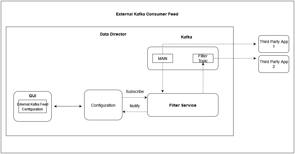
The Data Director provides the following support for external Kafka feeds:
- Creation, updating, and deletion of external Kafka Feeds using OCNADD User Interface (UI).
- Authorization of third-party Kafka consumer applications based on specific user, consumer group, and optional hostname.
- Display of status reports from third-party Kafka consumer applications utilizing external Kafka Feeds in the UI.
- Presentation of consumption rate reports from third-party Kafka consumer applications utilizing external Kafka Feeds in the UI.
Authorization by Kafka requires clients to undergo authentication through either SASL or SSL (mTLS). As a result, enabling external Kafka feed support requires specific settings to be activated within the Kafka broker. This ensures mandatory authentication of Kafka clients by the Kafka service. These properties are not enabled by default and must be configured in the Kafka Service before any Kafka feed can function.
See Enable Kafka Feed Configuration Support section before creating any Kafka Feed using OCNADD UI.
For Kafka Consumer Feed configuration using OCNADD UI, see Kafka Feed section in Configuring OCNADD Using CNC Console.
3.15 Centralized Deployment
The OCNADD Centralized deployment modes provide the separation of the configuration and administration PODs from the traffic processing PODs. The single management PODs group can serve multiple traffic processing PODs groups (called Worker Groups), thereby saving resources for management PODs in very large customer deployments spanning multiple individual OCANDD sites. The Management Group of PODs maintains configuration & administration, health monitoring, alarms, and user interaction for all the individual worker groups. The Worker Group represents the traffic processing functions and services and provides features like aggregation, filtering, correlation, and Data Feeds for third-party applications.
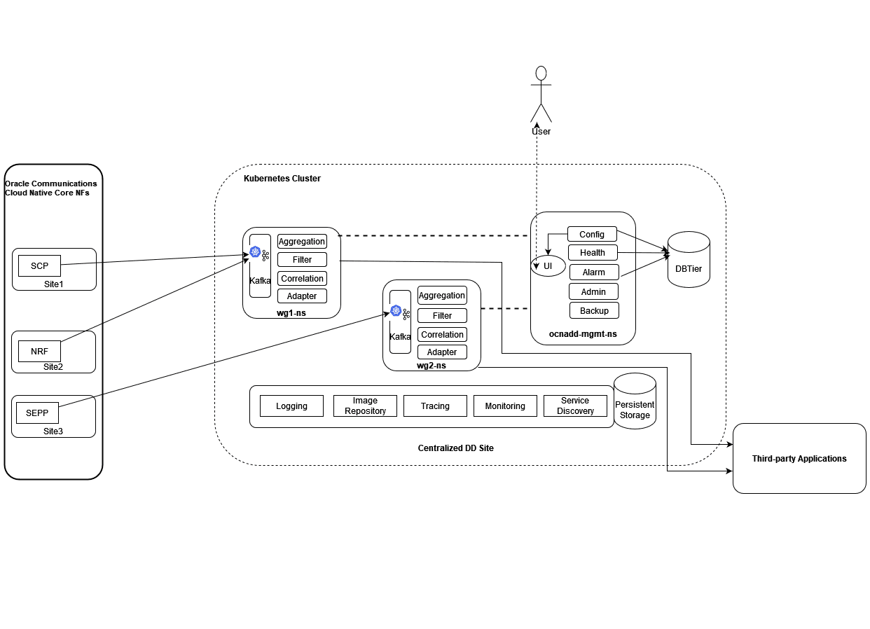
Management Group: A logical collection of the configuration and administration functions. It consists of Configuration, Admin, Alarm, HealthMonitoring, Backup, and UI services.
Worker Group: A logical collection of the traffic processing functions. It
consists of Kafka, Aggregation, Filter, Adapter, and Correlation services. The worker
group names are formed by worker group namespaces and site or cluster name
"worker_group_namespace:site_name".
Where,
- The site or Cluster name is a global parameter in the helm charts controlled by the
global.cluster.nameparameter. - Worker Group namespaces are:
- Default worker group namespace: The namespace name used in the Non-Centralized deployment. It will be used as the default worker group namespace name when upgrading from the Non-Centralized DD deployment mode to the Centralized deployment mode.
- In fresh deployments, it is the namespace name given to the worker group in the worker group charts.
The important points for Centralized deployment are:
- The Centralized deployment mode separates configuration management from traffic processing, enabling independent scaling of traffic processing units.
- Each worker group within a Centralized DD site can have different capacity configurations, but the maximum supported capacity for each worker group must be the same.
- Multiple worker groups can exist in a centralized DD site, supporting traffic rates based on the resource profiles of the worker group PODs. If the worker group is dimensioned for processing 100K MPS traffic and the Centralized DD site has a requirement to support 300~400K MPS then an additional worker group should be created on the centralized DD site.
- Metrics and alarms are generated separately for each worker group.
- Each Centralized DD site should support a fixed number of worker groups; the current release limits this to two.
- Releases 23.4.0 or later support fresh deployments in centralized mode only.
- Upgrading from previous supported releases to Centralized deployment mode is recommended.
- The UI facilitates the configuration of data feeds, filters, and correlation configuration creation specific to the worker group. For more information, see Configuring OCNADD Using CNC Console chapter.
3.16 Correlation Feature
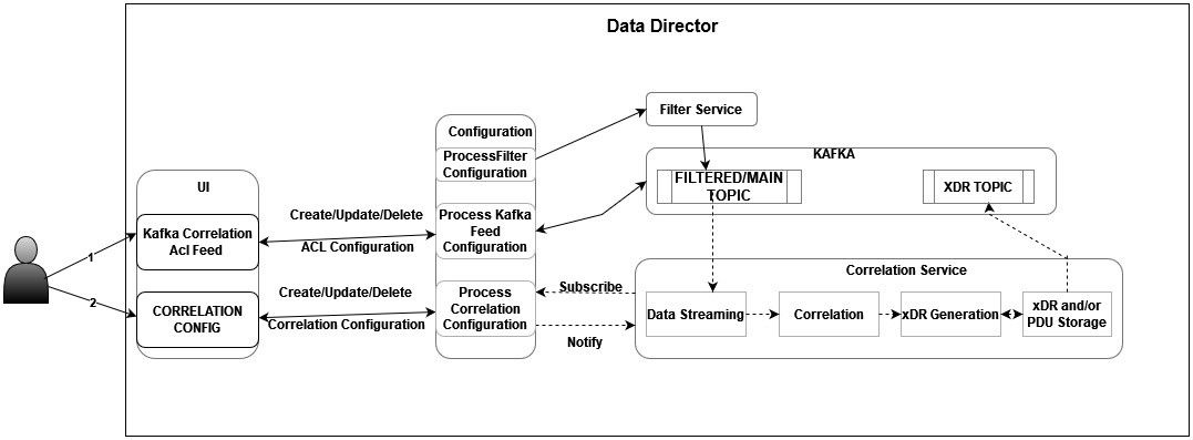
The correlation feature provides the capability to correlate messages within a network scenario, represented by a transaction, call, or session, and generate a summary record known as xDR. These generated summary records offer deep insights and visibility into the customer network, proving useful in various features such as:
- Network troubleshooting
- Revenue assurance
- Billing and CDR reconciliation
- Network performance KPIs and metrics
- Advanced analytics & observability
Network troubleshooting stands as a key feature in the monitoring solution. The correlation capability assists the Data Director in providing applications and utilities for troubleshooting failing network scenarios, tracing these scenarios across multiple NFs, and generating KPIs for network utilization and load. This capability enhances network visibility and observability. The KPIs and threshold alerts derived from xDRs offer intuitive insights, enabling reports like network efficiency reports displayed on network dashboards.
The xDRs generated by the Data Director facilitate advanced descriptive and predictive network analytics. The correlation output in the form of xDRs can be integrated into network analytics frameworks like NWDAF or Insight Engine. This integration empowers AI/ML capabilities beneficial in fraud detection, predicting and preventing network spoofing, and mitigating DOS attacks.
Note:
In case of an upgrade, rollback, service restart, or configuration created with the same name, duplicate messages or xDRs will be sent by correlation service to avoid data loss.For more details about Correlation configuration and xDR, see Correlation Feature Configuration and xDR Format.
For information about Kafka feed creation, correlation configuration, and xDR generation using OCNADD UI, see Creating Kafka Feed, Correlation Configurations, and OCNADD Dashboard sections.