4 Working with Conceptual Models
This chapter describes how you use Oracle Communications Design Studio to build a conceptual model of a service domain.
About Conceptual Models
Conceptual models define the relationships between your commercial products, the services that they represent, and the resources that are required to implement the services. They define how commercial products and technical services are related, and they enable you to associate the products that you sell with the technical services and resources that are required to fulfill orders.
Conceptual models comprise entities that represent components of a service but that contain no detailed application-specific information. The information that you define for conceptual model entities determines how service capabilities can be commercialized. For example, the conceptual model defines your products and services and the actions that must be performed in a run-time environment to provision a service order request.
When designing conceptual models, you define the associations among the conceptual model entities. You also define the patterns that are used to fulfill service orders and technical orders. These patterns define how requests to design reusable service components are fulfilled and how delivery systems activate and manage the work to be performed on resources in the network.
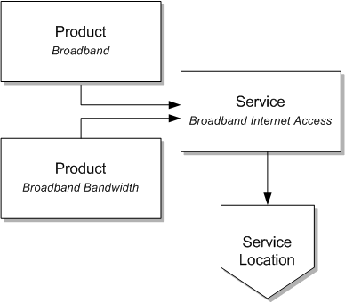
Figure 4-1 is a simple example that illustrates how a product (called Broadband) that is sold to a customer is fulfilled by a service (called Broadband Internet Access).
Figure 4-1 Conceptual Model: Products and Services
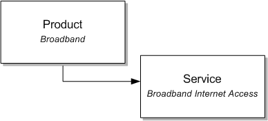
Description of "Figure 4-1 Conceptual Model: Products and Services"
Figure 4-2 expands on the example and illustrates how you can associate multiple products to the same service. The Broadband and Broadband Bandwidth products are now both associated with a single customer facing service, the Broadband Internet Access service. Also, you can associate the service to a specific location.
Figure 4-2 Conceptual Model: Products, Services, and Locations
Description of "Figure 4-2 Conceptual Model: Products, Services, and Locations"
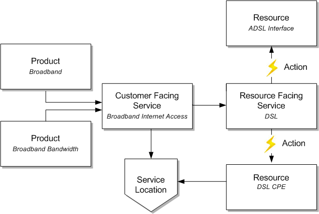
Conceptual models also include definitions of the actions that are required to provision a service. For example, you can define the actions necessary to add a DSL service for a new customer or disconnect an existing DSL service for an existing customer.
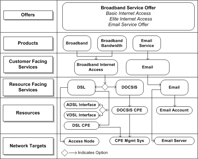
Figure 4-3 expands the example further. The example shows a small subset of the technical components required to provision the Broadband Internet Access service; for example, a resource facing service (DSL) and two resources (customer premise equipment and a DSL interface, named DSL CPE and ADSL Interface, respectively).
Figure 4-3 Conceptual Model: Products, Services, CFS, RFS, and Resources, and Actions
Description of "Figure 4-3 Conceptual Model: Products, Services, CFS, RFS, and Resources, and Actions"
Figure 4-4 is a simple conceptual model for a broadband domain.
You define conceptual models in Design Studio Model projects, which are not deployed to run-time environments. You convert conceptual model entities into application entities (you save application entities in application cartridge projects). This conversion is called realization. You can enrich the application-specific entities with additional configuration and deploy the application cartridge projects to run-time environments.
Conceptual model entities can also serve as placeholders for products and services that are not realized by Oracle Communications applications. For example, you can use conceptual models to enable Oracle Communications Order and Service Management (OSM) to work with external systems if you intend to associate conceptual model entities to applications that are not part of the Oracle Communications suite of applications.
About Conceptual Model Entities
A conceptual model includes the following entities:
-
Customer facing services (CFS), which represent services from a customer perspective. See "About Customer Facing Services" for more information.
-
Resource facing services (RFS), which represent a technical view of a service. See "About Resource Facing Services" for more information.
-
Resources, which represent the entities that are required to configure the service. See "About Resources" for more information.
-
Products, which represent commercial products. See "About Products" for more information.
-
Locations, which represent physical locations. See "About Locations" for more information.
-
Actions, which describe how conceptual model entities change, cause change, or retrieve information. Actions are associated with customer facing services, resource facing services, and resources. See "About Actions" for more information.
-
Action codes, which represent the specific types of actions permitted for each type of action. For example, an action can include a number of action codes to represent create, disconnect, and remove.
-
Action parameter bindings, which enable you to identify the conceptual model entities (such as a resource or a resource facing service) that contribute to the creation of technical actions, and to map the source data (a conceptual model entity, attributes defined for a conceptual model entity, and components defined for a conceptual model entity) to target data (parameters defined for technical actions). See "About Action Parameter Bindings" for more information.
-
Domains, which are groups of entities and actions that you can use to organize and filter solutions. See "About Domains" for more information.
The following conceptual model entities help to define the model infrastructure and rarely require updates. You can extend these entities to meet the requirements of a specific deployment:
-
Application roles, which represent types of downstream delivery systems that are responsible for specific types of delivery, such as activation, supply chain management, work force management, and so forth. See "About Application Roles" for more information.
-
Functional areas, which are the logical layers of an installation and can be commercial, service, and technical layers. These layers are supported by an OSM order type or by an external order management system. See "About Functional Areas" for more information.
-
Provider functions, which are processing components that perform a defined set of tasks based on their role in a solution. Provider functions comprise standard sets of unique capability, defined by the input the function accepts (an order or standard request), the output it generates (an order or standard request), and the data that drives the provider function description and purpose. Design Studio includes the configuration for some provider functions, such as Calculate Service Order, Design and Assign, Calculate Technical Order, and Activation. See "About Provider Functions" for more information.
-
Fulfillment patterns, which describe the high-level functions that are required to process an action or a conceptual model entity. See "About Fulfillment Patterns" for more information.
-
Fulfillment functions, which represent the work to be performed against an action. Fulfillment functions can be augmented with conditions to determine whether the function is to be performed against an action. See the Design Studio Help for more information.
About Customer Facing Services
Customer facing services represent the commercial view of the services that you provide to your customer (a service represents the way that a product is realized and delivered to a customer). You can use the same CFS to fulfill different but similar product offers. For example, the same Broadband_Internet_Access CFS can be used to fulfill an order for a Broadband product and a Broadband_Bandwidth product.
You relate the data elements defined for customer facing services to data elements defined on products. Additionally, you associate customer facing services with resource facing services (as components). For example, you can associate with a CFS the resource facing services available to fulfill the service, such as DSL or DOCSIS.
Service actions change a customer facing service. Service actions represent requests to change a customer facing service in the technical inventory. These actions are used during product-to-service mapping and during run-time Calculate Service Order and Design and Assign provider function activities.
Customer facing services are represented in Design Studio for Inventory as Service specifications and as Service Configuration specifications.
Customer facing services are associated with products through primary and auxiliary relationships. See "About Conceptual Model Entity Relationships" for more information.
Use the following set of guidelines when creating customer facing services:
-
Define customer facing services to support multiple products. A CFS can support multiple products if it is not defined for a specific technology.
-
Define customer facing services to include attributes of the service that are important to a customer, and hide technology details that are not relevant to a customer.
-
Define customer facing services to represent a single domain. For example, the Broadband_Internet_Access CFS represents the Broadband domain.
-
Define customer facing services with no explicit dependencies to other customer facing services. An explicit dependency is a direct relationship. Oracle does not recommend, for example, that you create a relationship between the Broadband_Internet_Access CFS and an Email CFS.
About Resource Facing Services
A resource facing service (RFS) describes how customer facing services are configured. For example, you can fulfill a customer facing service named Broadband_Internet_Access using multiple modes of delivery, each represented by a resource facing service, such as DSL, DOCSIS, or Fiber. You determine the resource facing service used to provide the commercial-level services during service design.
Resource facing services are technology-specific but not vendor-specific. Resource facing services have associations with resources or with other, finer-granulated resource facing services. For example, the DSL RFS has an association with the CPE (customer premise equipment) resource to represent a cable modem.
Resource facing services can be defined as targets for technical actions, which represent operations that make changes in the network. Resource facing services are represented in Design Studio for Inventory as Service specifications and as Service Configuration specifications.
About Resources
Resources are entities that are required to configure a service. A resource is a specific object in the network and in the inventory that can be consumed, referenced, or shared by a service when provisioning a resource facing service. Resources can be physical, such as a port, or logical, such as bandwidth. Examples of resources include IP addresses, VoIP phones, and DSLAM ports.
Resources have associations with other resources and can be defined as targets for technical actions.
Technical actions represent changes to the network. For example, a technical action to add customer premise equipment (CPE) is defined with the data required by the network to recognize the connection made by the new CPE.
Resources can be converted to Design Studio for Inventory entities. See "About Realizing Resources in Design Studio for Inventory" for more information.
Additionally, you can define resources that you intend to realize in external systems and realize the entities manually. You can also define resources as Other if no Design Studio for Inventory resources meet your business requirements, and realize the entities manually. See "About Conceptual Model Realization" for more information.
About Products
A product is an entity that your business sells. A product defines a set of product characteristics, validation rules, and relationships. For example, you might create products for Broadband, Broadband_Bandwidth, and Email products.
You can create products in Design Studio, or you can import products into Design Studio. For example, when new products are added to the product catalog, the corresponding product must be imported into Design Studio. After you create or import products, you can create or review the associated attributes in the Product editor.
Products are used by orchestration processes to map order lines to fulfillment actions and to map order lines to Service specifications.
Note:
Conceptual model products are not realized as application entities.
For products, you define primary and auxiliary relationships to customer facing services. See "About Conceptual Model Entity Relationships" for more information.
Use the following guidelines when creating products:
-
Ensure that your products represent functionality meaningful to a customer.
-
Define products to facilitate reuse in multiple bundled offers. Minimize overlap among product definitions to ensure that a simple assembly of product offers can be maintained. Duplication among product definitions can complicate customer relationship management processes and increase operations cost.
-
Define products so that they do not expose unnecessary details. For example, a Broadband product includes only data elements that represent the properties of the service being ordered, such as upload speed, download speed, service address, customer ID, and so forth. Products do not include data elements that represent technical elements of the service, such as the MAC address or IP address of the home location register (HLR) server.
About Locations
A location represents a geographical place that is relevant to services or resources. Locations are realized as Design Studio for Inventory Place specifications defined as type Site. For example, in a Broadband service, the DSL RFS for a DSL service can be associated with a location to represent the address of the customer.
When realizing Location entities, Design Studio also creates a Place Configuration specification.
About Domains
A domain is a group of entities and actions that you can use to organize and filter solutions (you do not realize domain entities as application entities). For example, you can create a domain called Alcatel_DSLAMs that contains the resources (the Alcatel devices) that can be used as a DSLAM. You can include conceptual model entities in multiple domains, and you can create a hierarchy of domains that include subdomains. Subdomains can decompose into smaller groupings (for example, into broadband products and broadband services). Domains can be used as subdomains, and subdomains can be shared across multiple domains.
You can filter the Solution view to display domains and view and navigate among only those entities that are associated with domains.
At run time, the Order and Service Management application uses the domain and the provider function to decide which transformation sequence to use. For example, to ensure that the TS-1 transformation sequence is always used for the Mobile domain and that the TS-2 transformation sequence is always used for the Carrier Ethernet domain, you would model the data in Design Studio such that the Mobile domain and CSO provider function combination uses TS-1 and the Carrier Ethernet and CSO provider function uses TS-2.
About Application Roles
An application role represents a type of downstream delivery system that is responsible for a specific type of delivery, such as activation, supply chain management, work force management, and so forth. Design Studio includes a set of predefined application roles. You can create your own application roles using the Application Role editor.
When you create a new action, Design Studio prompts you to select an action type of service or technical. If you select an action type of technical, Design Studio requires that you also select an application role. Design Studio populates the Action editor Action Codes tab with the specialized action code names defined for the application role. A specialized action code is an action code that you rename to align a technical action with a downstream fulfilment system.
For example, you may need to rename the Create action code to Activate to better align with code defined in a downstream activation system. For a supply chain management system, you may need to rename the Create action code to Ship. You may need to rename the Remove action code to Uninstall to better align with a downstream workforce management system.
Additionally, the Application Role editor enables you to define multiple specialized action code names for each default action code. For example, a downstream fulfillment system may require multiple versions of the Modify action code. You can differentiate between these versions by defining two unique specialized action code names, such as Change and Revise.
About Provider Functions
Provider functions are processing components that perform a defined set of tasks based on the provider function role in a solution. Design Studio includes the configuration for some provider functions, such as Calculate Service Order, Design and Assign, Calculate Technical Order, and Activation.
Provider functions accept conceptual model entities and the actions that are associated with those entities as input and generate conceptual model entities or their actions as output. The output that provider functions generate is used as input by other, downstream provider functions. Calculate Service Order accepts products as input and generates the service actions associated with customer facing services as output. This output is required as input by the Design and Assign provider function, which generates output that is required by the Calculate Technical Order provider function.
For example, during the fulfillment of a new wireless voice service, the Design and Assign provider function creates instances of Service specifications and Service Configuration specifications that are required to deliver the service (the telephone number, the bandwidth, and so forth). Information about these specifications and the actions that are associated with them is used by Calculate Technical Order to calculate the difference between the current and the requested state of a configuration and to identify the technical actions that are required to achieve the requested changes.
Provider function definitions determine the types of components that are available to model for a conceptual model entity. A conceptual model entity is associated with a provider function when the conceptual model entity is defined as an input type. The components that you can define for a conceptual model entity are limited to the output types defined on all provider functions with which the conceptual model entity is associated.
For example, consider that you are defining components for a Customer Facing Service entity, and that there exists in the workspace only one provider function, named Design and Assign. And, consider that this provider function defines the Customer Facing Service entity as input and defines the Resource Facing Service entity and the Location entity as output.
In this example, when configuring components for a Customer Facing Service entity, you can define as components only resource facing services and locations. If you need to add the resources as components of a customer facing service (such as when modeling a Carrier Ethernet) you can edit the Design and Assign provider function definition to add the Resource entity an output type.
Provider functions are associated with OSM transformation sequences and orchestration processes.
About Functional Areas
Functional areas describe the logical layers of an installation, and can be commercial, service, and technical layers. These layers are supported by an OSM order type or by an external order management system.
When configuring functional areas, you specify whether the functional area supports actions. If it does, you indicate which conceptual model entities support the type of actions defined by the functional area and whether these actions are multi-instance. For example, the Service functional area supports actions, but only on customer facing services, resource facing services, and resources. The Technical functional area also supports actions, but those actions can be associated only to resource facing services and resources.
You can define default data elements for service actions associated with a functional area. When a service action is created, the default data elements defined in the Functional Area editor appear on the Service Action editor Data Elements tab. The data elements that you add to a functional area are automatically associated with an implicit parameter tag to make the data elements read-only in the Service Action editor.
Functional areas are associated with a list of action codes. Each action code represents an action that can be performed on a conceptual model entity. When a new action of the type defined by the functional area is created, all of the action codes defined in the functional area are added to the new action. You can define the applicability of each default data element to the service action codes associated the functional area.
About Fulfillment Patterns
Fulfillment patterns define a set of high-level functions that can be performed to process an action or conceptual model entity. For example, a fulfillment pattern can define the functions that are required to process conceptual model entities and actions for provisioning, billing, or installation. In OSM, you associate fulfillment patterns with the processes that execute the order items.
You can associate any conceptual model entity or action to a fulfillment pattern. For example, you can associate multiple products to one fulfillment pattern, which enables you to introduce new products with minimal configuration in Design Studio. Fulfillment patterns realize as OSM fulfillment patterns.
About Fulfillment Functions
Fulfillment functions are operations that can be performed to process an order item. In the context of the conceptual model, the line item is an action or a product. After you create fulfillment functions, you associate them with fulfillment patterns. You also associate actions with fulfillment patterns, and the fulfillment pattern associated with any action determines which fulfillment functions can be associated with the action.
Fulfillment functions can be realized as OSM Order Component specifications. In OSM, line items are sent to a fulfillment pattern, which includes a set of order components that can be used to process the line item. The order components represent work that needs to be done against the line item. The fulfillment pattern determines which order components are to be used based on the conditions and dependencies defined in OSM. Each order component can have dependencies to other components (for example, one component may require that another be completed first).
About Action Parameter Bindings
Action parameter bindings represent the aggregate of an entity and its parameters in the context of an application role. They enable you to identify the conceptual model entities (such as a resource or a resource facing service) that contribute to the creation of technical actions, and to bind the source data (a conceptual model entity, attributes defined for a conceptual model entity, and components defined for a conceptual model entity) to target data (parameters defined for technical actions).
A technical action represents a unit of work that is performed to realize a resource or a resource facing service in a network. Technical actions are performed by a fulfillment system. For example, an activation system performs technical actions to configure a network; a shipping system performs technical actions to pick, pack, and ship physical goods; and a work force management system performs technical actions to dispatch work to a technician.
During service order fulfillment, a design and assign process produces a service configuration that defines the technical actions that must be executed to fulfill the requested service action. The subject and the target of a technical action each bind to a resource or to an RFS that is assigned to or referenced by a CFS or by an RFS service configuration. A technical action also defines parameters that describe the work to be done, and these parameters also bind to properties of a resource or of an RFS assigned to or referenced by the service configuration. In Design Studio, you model these bindings in Action Parameter Binding entities.
At run-time, after a requested service is designed, a calculate technical actions process compares the current configuration against the requested configuration. To determine if there are differences between the current and requested configurations, the process analyzes the action parameter bindings and determines whether any of the parameters have differences. A difference in any parameter means that the technical action must be performed (but only under specific conditions; for example, a technical action may be required only when a subject resource is newly allocated). Using this method, the calculate technical actions process identifies all of required technical actions that must be performed to affect the necessary changes in the network (and to activate the services).
About Action Parameter Bindings and CTA Metadata
The process that compares a current configuration against a requested configuration is called the Calculate Technical Actions (CTA) provider function. The metadata that is necessary for the CTA provider function to calculate the delta is contained in an XML file for each Service specification in the Inventory system. Action parameter bindings help you create the metadata in the XML files by graphically illustrating how the attributes in the conceptual model contribute to the parameters in the technical actions.
The CTA metadata in the XML files is not, however, generated automatically in Design Studio. Rather, Design Studio enables you to complete the modeling necessary to facilitate the CTA processes. To automate the creation of CTA metadata, you must develop a CTA metadata generator. This generator explores the conceptual model configuration and generates the necessary metadata.
You can leverage the Design Studio Exchange Format and create your own CTA metadata generator, or you can use the example that is included in the Oracle Communications RSDOD Reference Solution, which is available on the Oracle Technology Network. See Design Studio Developer's Guide for more information about the Design Studio Exchange Format. See the Oracle Communications RSDOD Reference Solution Developers Guide for more information about generating CTA metadata.
About Conceptual Model Entity Relationships
The conceptual model entities and the relationships among them form a model of your service domain. These associations are called named relationships, and you add named relationships to entities by defining components.
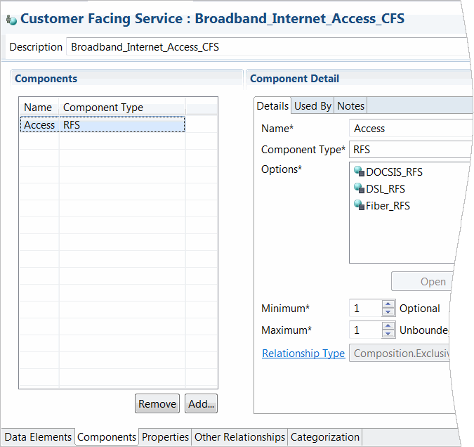
A component is a container that represents all of the viable configurations that can be defined for the relationship. For example, the Broadband_Internet_Access customer facing service (CFS) can include the Access component. The Access component represents all of the resource facing services that can be used to deliver the Broadband_Internet_Access service.
Note:
The types of components that are available to model for conceptual model Customer Facing Service, Resource Facing Service, and Resource entities are determined by provider function definitions. See "About Provider Functions" for more information.
When you first begin modeling, you may not have information about a component except for the name and component type. For example, early in conceptual model design, you may not yet have specific details about the Access component except to know that the Broadband_Internet_Access CFS requires specific technologies to support the service. The Access component name describes the role of the relationship (Access) and the component type describes the specification (a resource facing service).
To complete the model, you define the component options. For example, the Access component may include DSL, Fiber, and DOCSIS options. Figure 4-5 illustrates how these options are instances of resource facing services, and they all represent viable resource facing services that can support access for the Broadband_Internet_Access CFS. The type of access that you provision may depend on the geographic location, where one location requires you to use DSL, another requires you to use DOCSIS, and a third requires Fiber.
Figure 4-5 Defining Conceptual Model Components
Description of "Figure 4-5 Defining Conceptual Model Components"
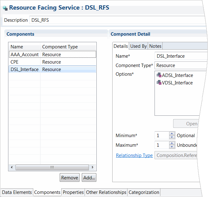
Figure 4-6 illustrates how the DSL RFS also has named relationships defined as components. For example, the DSL RFS can have an Account component, a CPE (customer premise equipment) component, and a DSL_Interface component. Each of these components defines the viable resources that can be used to provision a service in the network. For example, the DSL_Interface component can be defined with two options: an ADSL_Interface resource and a VDSL_Interface resource.
Figure 4-6 Defining Components at the RFS Level
Description of "Figure 4-6 Defining Components at the RFS Level"
About Relationship Types
Conceptual model entities have associations with other entities through named relationships, which are defined as components. Each component associated with a conceptual model entity is defined with a specific relationship type.
The following relationship types exist in Design Studio:
-
Primary relationships are used to associate products to services. In a run-time application, this type of relationship is used to instantiate a new service order line. The Primary type defines relationships between a product and a customer facing service (CFS). For example, when a customer orders the Mobile product, the Mobile CFS fulfills the order; the CFS connects the ordered product with the technical aspects required to fulfill the product services.
For each product, you define a Primary relationship to a single CFS. Every CFS must have a Primary relationship defined with at least one product.
In some scenarios, the Primary type can define a relationship between a product and a resource. For example, if a customer orders a mobile phone case, there is no service required to provision the case. In this scenario, you associate the Case resource with the Mobile product.
-
Auxiliary relationships are used to associate products to services, but this type of relationship is used by run-time applications to enrich existing service order lines (it does not instantiate a new order line). The Auxiliary type defines relationships between a product and a CFS (and in some rare cases, between a product and a resource).
A CFS can define any number of Auxiliary relationships with products, but the Auxiliary relationships cannot exist independent of a Primary relationship. For example, the Mobile product may include a number of features, such as call waiting, caller ID, and so forth. Each of these features may be defined as a product. The Mobile product defines a primary relationship to the Mobile CFS. The CallerID product and the Call_Waiting product both define auxiliary relationships to the Mobile CFS.
-
Exclusive relationships are used to model run-time constraints that ensure that entities are not shared with other service instances. For example, telephone numbers cannot be used by multiple instances of a mobile service. In this example, there is an exclusive relationship between the Mobile resource facing service (RFS) and the TelephoneNumber resource. The Exclusive type defines relationships among CFSs, RFSs, and resources.
-
Shared relationships are used to model run-time constraints to ensure that source entities can be shared with other service instances. For example, because an HLR can maintain several user accounts simultaneously (and is not exclusive to any one service), there is a shared relationship between the Mobile RFS and the HomeLocationRegister resource.The Shared type defines relationships among customer facing services, resource facing services, and resources.
-
Reference relationships are used to model run-time constraints to ensure that a target entity references a source entity. For example, you define a Reference relationship between a Broadband CFS and a London location (representing the geographical address). When defining Reference relationships, there is no source entity capacity requirement. The Reference type defines relationships among customer facing services, resource facing services, and resources.
-
ConfigHierarchy relationships are used to model a specific run-time constraint in Oracle Communications Unified Inventory Management (UIM) in which no real entity is referenced. Instead, an intermediate hierarchical structure is referenced at run-time. You can use this new relationship to characterize the relationship between a resource facing service and a resource component. The ConfigHierarchy relationship indicates that a UIM realization of a resource component should result in a hierarchy of configuration items and should not generate a UIM entity.
About Actions
Design Studio includes the definitions for two action families, service and technical:
-
Service Actions are the signatures of design operations that apply to customer facing services, resource facing services, or to resources. Actions are executed at run-time to initiate design and assign activities. Service actions are grouped into families that represent the range of operations that can be invoked on the entity, and each action consists of a specific set of parameters.
These actions are used during product-to-service mapping and during run-time Calculate Service Order and Design and Assign provider function tasks. Service actions include a group of action codes, each of which can be performed against the associated specification. For example, a service action can affect change to a customer facing service because it includes the action codes Add, Move, and Delete.
-
Technical actions are requests to downstream delivery systems to make changes in the network (the downstream delivery systems are represented by an application role). Technical actions are associated with resource facing services or with resources. Technical Action entities do not inherit the data elements defined on the associated specification because technical actions can include data elements defined on any entity in the conceptual model. Technical Action entities are realized as Design Studio for ASAP service actions (CSDLs) or as Design Studio for Network Integrity scan actions.
Conceptual model entities are the subjects of actions. You associate actions with entities to indicate that the action or group of actions can be performed against the associated entity. You can create your own actions, or you can configure Design Studio to create actions automatically when you create new entities.
All customer facing services are associated with one service action only. By default, when you create new customer facing services, Design Studio automatically creates a new Service Action entity and associates it with your new CFS. The new Service Action entity inherits all of the data elements defined on the CFS. This default inheritance enables you to keep the data synchronized between customer facing services and the service actions that are performed on the customer facing services.
Also, the service action includes a set of default data elements that are inherited from the associated functional area. These default data elements are associated with the Implicit Parameter tag (in the Functional Area editor) and they are not editable.
A service or technical action must have access to a specific set of data required to perform the action against an entity, and you identify which of the inherited data elements are applicable to the action. On the Action editor Data Map tab, you can specify whether a data element is required by an action by defining applicability to specific action codes (for service actions) or by defining applicability to specialized aliases defined for the action codes (for technical actions). For example, you can specify whether a data element value must be supplied to or returned by each action in an associated action family. You can overwrite the applicability settings for inherited data elements, and you can change the information defined for the data elements inherited from the functional area.
You can associate resource facing services and resources with one service action and with multiple technical actions. For example, a resource that represents customer premise equipment can be the subject an action that ships the equipment to a customer, and can also be the subject of an action that facilitates the return of the equipment.
Conceptual model service actions are realized as Design Studio for Inventory rulesets. Conceptual model technical actions are realized as Design Studio for ASAP service actions (CSDLs) or as Design Studio for Network Integrity scan actions.
About Conceptual Model Realization
In Design Studio, realization is the conversion of a conceptual model entity into an application entity. Conceptual model entities represent abstractions of services, so you cannot deploy conceptual model entities to run-time environments. Rather, you convert conceptual model entities into application entities, and then deploy the application projects that contain the realized entities to run-time environments.
You run design patterns to realize conceptual model entities. When creating a conceptual model entity, you identify which application entity it realizes and which design pattern performs the realization.
You realize the following conceptual model entities:
-
Customer facing services and resource facing services, which are realized in Design Studio for Inventory projects as Service specifications and as Service Configuration specifications. See "About Realizing Services in Design Studio for Inventory" for more information.
-
Resources, which are realized in Design Studio for Inventory projects as Inventory entities. For example, you can realize resources as Logical Device specifications, Logical Device Account specifications, Telephone Number specifications, and so forth. When realizing Resource entities, Design Studio also creates a configuration specification. See "About Realizing Resources in Design Studio for Inventory" for more information.
-
Service actions, which are realized in Design Studio for Inventory projects as rulesets and Java code structures. However, design patterns do not automatically generate rulesets, so you must create the rulesets in an Inventory project. The Design Patterns and code generators for realizing Service Actions are packaged with the SNO Reference Implementation.
-
Technical actions, which are realized in Design Studio for ASAP projects as service actions or in Design Studio for Network Integrity projects as scan actions. Realizations of signatures for other downstream delivery systems can be supported by crafting Design Patterns that support these delivery systems.
-
Action parameter bindings, which are realized for Inventory projects as metadata that controls the behavior of Calculate Technical Order Functionality. The metadata generator for realizing Action Parameter Bindings is packaged with the SNO Reference Implementation.
-
Locations, which are realized in Design Studio for Inventory projects as Place specifications defined as type Site. Design Studio also generates a corresponding Place Configuration specification. See "About Realizing Locations in Design Studio for Inventory" for more information.
-
Fulfillment patterns, which are realized in Design Studio for OSM projects as fulfillment patterns.
About Design Patterns That Realize Conceptual Models
Design Studio design patterns are wizards that automate complex, repeatable tasks that team members can perform. Design Studio includes default design patterns that you can use to automate the realization of conceptual model entities into application entities. You run these design patterns using the Design Pattern wizard and you can set up conceptual model entities to run the design patterns automatically. You can also create your own design patterns. See "Working with Design Patterns and Guided Assistance" for more information about design patterns.
After you run a conceptual model entity's design pattern once, Design Studio automatically reruns design pattern when you make changes to the entity.
When a design pattern creates a realized application entity, the pattern uses the name of the conceptual model entity as a prefix for naming the realized application entity. For example, you create a customer facing service (CFS) named Broadband and then run the Default Customer Facing Service Realization design pattern for the Broadband CFS entity. When configuring the design pattern, you provide values for the Major, Minor, and Fix configuration version fields, for which, for example you might input 1, 0, and 0, respectively. When the pattern is run, Design Studio creates a Service Specification entity named Broadband and a Service Configuration Specification entity named Broadband_Configuration_v1-0-0.
Note:
See the Design Studio Help for more information about renaming conceptual model entities subsequent to application entity realization.
You can keep conceptual model entities and the realized application entities synchronized so that any changes you make to the conceptual model entities are automatically updated in the application entities. However, changes that you make to application entities are not automatically updated in conceptual model entities.
Design Studio conceptual model design patterns are associated by hierarchical relationships so that when you synchronize the conceptual model entity with the application entity, the design pattern automatically runs all relevant child design patterns to realize the entire conceptual entity tree.
For example, you define a CFS with two associated resource facing services (RFS), and each RFS includes three resources. The first time that you run the Default Customer Facing Service Realization design pattern, the Design Pattern wizard prompts you to input the information it requires to run the pattern. When the design pattern completes, Design Studio automatically runs the Default Resource Facing Service Realization design pattern twice (once for each RFS) and the Default Resource Realization design pattern six times (once for each resource in each RFS).
About Realizing Services in Design Studio for Inventory
When you realize customer facing services and resource facing services using the Default Customer Facing Service and the Default Resource Facing Service design patterns, the design patterns automatically create Design Studio for Inventory Service specifications and Design Studio for Inventory Service Configuration specifications. The design patterns save these specifications in the Inventory project that you specify when running the design pattern.
Only those data elements tagged as a Characteristic (at the Data Dictionary level) and as Persisted (on the conceptual model entity) are added to the Service specification during realization. When you add data elements to Resource Facing Service, Resource, and Location entities, Design Studio automatically applies the Persisted tag to data elements. When adding data elements to Customer Facing Service entities, you must apply the Persisted tag, if applicable.
You can also tag data elements as Changeable if you expect these elements to change frequently or if you need to track the life cycle of a service. When realizing customer facing services and resource facing services, the default design patterns save data elements that are tagged as Changeable to the Service Configuration specifications. Also, the design patterns save structured data elements to the corresponding Service Configuration specification. Data elements that are tagged as Changeable and Persisted, and structured data elements that are tagged as Persisted are added to the Service Configuration specification (as configuration items) during realization.
See the Design Studio Help for more information about using tags.
Note:
When realizing conceptual model entities for Inventory, ensure that all data elements defined on the conceptual model entity refer to a base element.
For example, if on the conceptual model entity you define a structured data element with child data elements, ensure that the child data elements all reference a base element. During realization, the structured data element is added to the Configuration specification as a configuration item. Child structured data elements are added to the Configuration specification as child configuration items. Child simple data elements are added to the Configuration specification as characteristics.
About Realizing Service Components
When customer facing services and resource facing services define components, the Customer Facing Service Realization design pattern and the Resource Facing Service Realization design pattern create a configuration item for each component that resolves to a conceptual model entity that can be realized.
The default design patterns add the configuration item to the Service Configuration specification. The design patterns also do the following:
-
Tag the configuration items as Realization Item, which identifies the element as data that is realized from a conceptual model specification to an Inventory configuration item.
-
Add specification options to the configuration items. See Modeling Inventory in the Design Studio Help for more information about specification options.
-
Assign the specification option Item Option Type value based on the relationship type defined between the conceptual model entity and the component. See Modeling Inventory in the Design Studio Help for more information about specification options.
-
Remove orphaned data elements and add new data elements, configuration items, and specification options during synchronization.
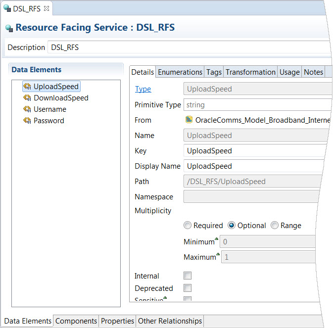
For example, a DSL_RFS resource facing service can define simple data elements, as illustrated in Figure 4-7. The UploadSpeed simple data element is tagged as a Characteristic, as Changeable, and as Persisted:
In this example, the DSL_RFS resource facing service also defines three resource components: AAA_Account, CPE, and DSL_Interface, as illustrated in Figure 4-8:
Figure 4-8 also shows that the DSL_Interface component is defined with two options, the ADSL_Interface resource and the VDSL_Interface resource. When you define multiple options for a component, you also define rules to determine which option is used at run time. You define these rules on the Rules tab of the Service Configuration specification.
When you realize the DSL_RFS service using the Resource Facing Service Realization design pattern, the pattern creates a Service specification and a Service Configuration specification. Data elements defined on the DSL_RFS service are saved to the Service Configuration specification if they are defined as Changeable. Additionally, the design pattern saves all structured data elements to the Service Configuration specification.
Resource components are added as configuration items on the Service Configuration specification. In this example, the resource components AAA_Account, CPE, and DSL_Interface are added as configuration items on the Service Configuration specification, as illustrated in Figure 4-9:
Figure 4-9 Configuration Items Defined on the Service Configuration Specification
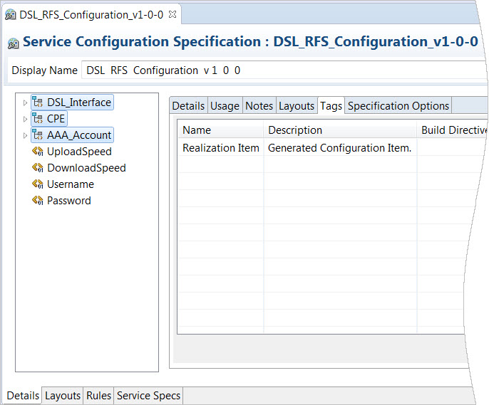
Description of "Figure 4-9 Configuration Items Defined on the Service Configuration Specification"
When you run the Resource Facing Service Realization design pattern, you can select the Create Nested Configuration Items option to include a more detailed data tree on the service configuration. When you select this option, the components defined for resources are added to the service configuration as child configuration items. This configuration item hierarchy is the realization of all resources that are modeled as components on a resource facing service.
For example, the DSL_RFS resource facing service defines the CPE component. The CPE component defines a single option, the DSL_CPE component, as illustrated in Figure 4-10:
Figure 4-10 The CPE Component and the DSL_CPE Option
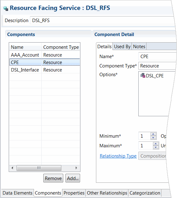
Description of "Figure 4-10 The CPE Component and the DSL_CPE Option"
The DSL_CPE component defines a single option, the VoD_Access component, as illustrated in Figure 4-11:
Figure 4-11 The DSL_CPE Resource and the VoD_Access Component
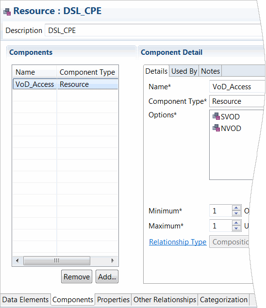
Description of "Figure 4-11 The DSL_CPE Resource and the VoD_Access Component"
In this example, after the Resource Facing Service Realization design pattern is run with the Create Nested Configuration Items option selected, the design pattern adds to the DSL_RFS Service Configuration specification a child configuration item for the video on demand component, VoD_Access, as illustrated in Figure 4-12:
Figure 4-12 Resource Attributes and Components Added as Child Configuration Items
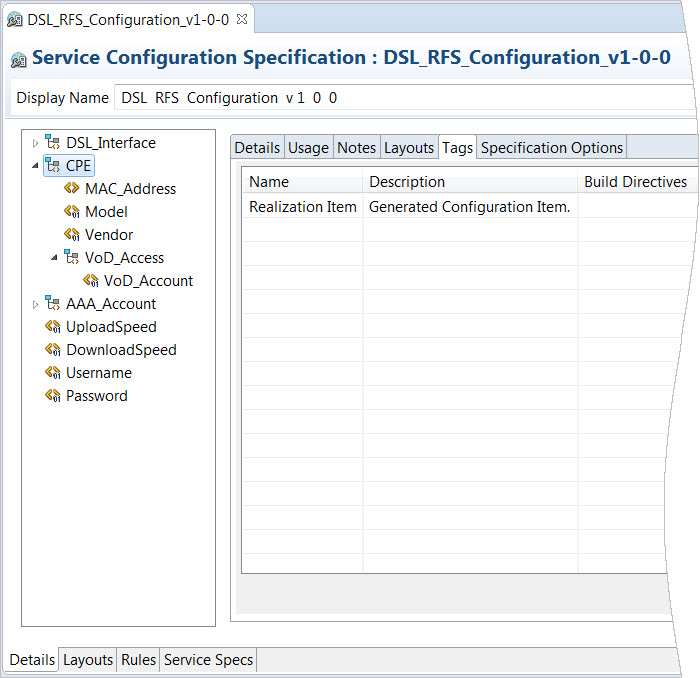
Description of "Figure 4-12 Resource Attributes and Components Added as Child Configuration Items"
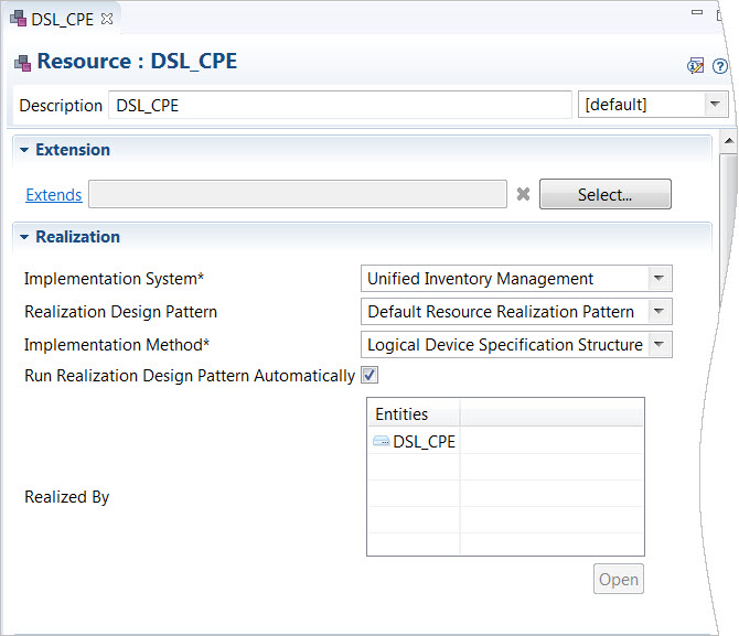
Figure 4-13 shows how the DSL_CPE resource realization is configured (in the Realization area) and shows the realized application entity, an Inventory Logical Device specification named DSL_CPE (in the Realized By table):
The DSL_CPE Logical Device specification appears as a specification option for the CPE configuration item on the Service Configuration specification, as illustrated in Figure 4-14:
Figure 4-14 Specification Options Defined for Configuration Items

Description of "Figure 4-14 Specification Options Defined for Configuration Items"
About Realizing Resources in Design Studio for Inventory
When you create a conceptual model Resource entity, you define how the resource is realized in Inventory by selecting an Inventory resource as the implementation method. When you realize resources using the Default Resource Realization design pattern, the design pattern creates an Inventory entity specification and creates a corresponding Configuration specification.
When you realize resources with one of the following implementation methods, the design pattern creates the Inventory entity and a corresponding Configuration specification:
-
Logical Device Account
-
Logical Device
-
Flow Interface
-
Network
-
Pipe
When you realize resources with one of the following implementation methods, the design patterns creates an Inventory entity, a Configuration specification of type Logical Device, and a Logical Device specification container that includes the name of the resource:
-
Connectivity
-
Customer Network Address
-
Custom Object
-
Device Interface
-
Flow Identifier
-
IPv4Address
-
IPv6Address
-
Media Stream
-
Property Location
-
Telephone Number
The default design pattern saves data elements tagged as Characteristic (at the Data Dictionary level) and as Persisted (on the conceptual model entity) to the specification, and saves data elements that are tagged as Characteristic, Persisted, and Changeable to the Configuration specification. Also, the design pattern saves structured data elements tagged as Persisted to the Configuration specification (as configuration items).
You can define the implementation method as a resource that exists outside of Inventory if the entity must realize as a resource that is different from the available realization options. When you select this option, there is no design pattern that generates a realization entity in Design Studio for Inventory (you can, however, write your own design pattern). See Design Studio Developer's Guide for more information about developing design patterns.If you elect to create nested configuration items when running the Default Resource Facing Service Realization design pattern, resource components and their data elements are saved to the Service Configuration specification as child configuration items. Design Studio adds structured data elements to the Service Configuration specification and adds simple data elements to the Service Configuration specification if they are defined with the Changeable tag.
About Realizing Locations in Design Studio for Inventory
A location represents a geographical place that is relevant to services or resources. The Default Location Realization design pattern generates a Place specification defined as type Site and a generates a corresponding Place Configuration specification. The Location Realization (deprecated) design pattern generates a Place specification of type Address. To generate a Place specification defined with a different type, you must navigate to the realized entity and change the entity type, or create your own design pattern.
The Default Location Realization design pattern saves data elements tagged as Characteristic (at the Data Dictionary level) and as Persisted (on the conceptual model entity) to the Place specification, and saves data elements that are tagged as Characteristic, Persisted, and Changeable to the Place Configuration specification. Also, the design pattern saves structured data elements tagged as Persisted to the Place Configuration specification.
About Realizing Technical Actions in Design Studio for ASAP
Service Action entities in Design Studio for ASAP are realized from conceptual model Technical Action entities.
Technical action families include a set of action codes that are mapped to a corresponding set of specialized action names that are specific to an application role. The action codes that initially appear are those defined by the action type (or the Technical functional area).
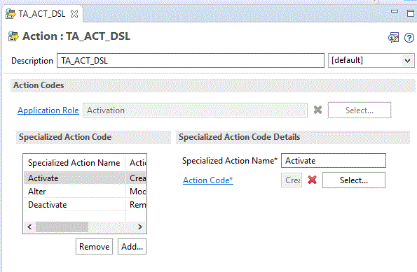
For example, Figure 4-15 shows a technical action named TA_ACT_DSL. This technical action includes the action codes Create, Modify, and Remove, which are mapped to the specialized action names Activate, Alter, and Deactivate. The specialized action names are specific to the Activation application role.
Note:
Technical Action Generation design pattern may not work in end-to-end scenario because of the naming and the action code discrepancies.
Figure 4-15 Technical Action Editor Action Codes Tab
Description of "Figure 4-15 Technical Action Editor Action Codes Tab"
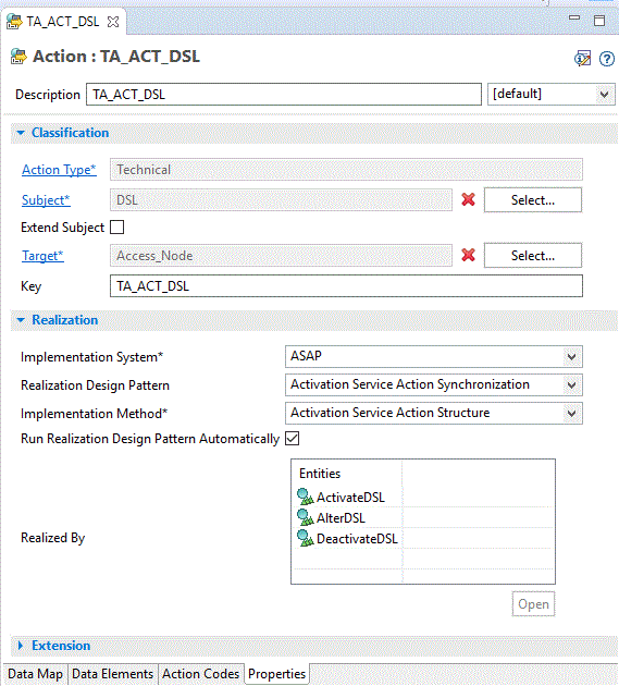
After you run the Activation Technical Action Realization design pattern, keep the conceptual model Technical Action entities and the ASAP Service Action entities synchronized by running the Activation Service Action Synchronization design pattern. Figure 4-16 illustrates how to set up a technical action that is realized by an ASAP service action.
Figure 4-16 Technical Action Editor Properties Tab
Description of "Figure 4-16 Technical Action Editor Properties Tab"
After you complete the realization, the Solution view displays the entities and the relationships among them.
About Conceptual Model Synchronization
You synchronize conceptual model entities with application model entities to ensure that the configuration of the application entities and the related conceptual model entities remain aligned.
After you realize conceptual model entities into application-specific entities, you can enrich the application entities with data required by the application. During this process, you may be required to change the entities in the application project. For example, you may need to add new characteristics to a Service specification that is realized from an RFS. If the data that you add is required by multiple entities across applications, Oracle recommends that you make the change to the associated conceptual model specification, then synchronize the projects.
When you synchronize conceptual model and application projects, Design Studio does not modify or delete the data elements that you defined on the application entities. During synchronization, Design Studio recreates in the application entities only the data elements and configuration items inherited from the conceptual model entities.
You synchronize conceptual model entities with application model entities by re-running the realization design patterns. You can configure these design patterns to run automatically (when an entity is saved), or you can run the design patterns manually by selecting a pattern from a context menu. Also, you can perform a bulk update by running a design pattern for an entity and instructing Design Studio to run all required design patterns for all child entities in the hierarchy.
Before you can synchronize a conceptual model entity and an application entity, you must realize the conceptual model entity in an application project. You provide data in the Design Pattern wizard that Design Studio uses to generate the application-specific configuration. To keep the entities synchronized, Design Studio re-runs the design pattern in the background using the data that you previously specified.
If you do not want to synchronize automatically, you can synchronize manually. For example, if you need to track all changes to conceptual model entities and application model entities, you can disable automatic synchronization until you have finished the analysis and determined the impact of the changes. When finished, you can select Synchronize All from the context menu to perform a bulk update on a hierarchy of conceptual model entities. See the Design Studio Help for more information.
You can synchronize the following conceptual model entities with their associated application entities:
-
Customer Facing Service
-
Resource Facing Service
-
Resource
-
Location
If you rename a conceptual model entity, and you subsequently use the Design Studio synchronize feature to ensure that the configuration of the application entities and the related conceptual model entities remains aligned, Design Studio looks for a realized application entity with the same name as the conceptual model entity. If no application entity with the same name exists, Design Studio creates a new application entity. In this scenario, Design Studio creates two realized entities, one created initially with original name, and one created after synchronization with the new name.
To avoid creating multiple realized entities after renaming a conceptual model entity, you must manually update the realized application entity names before using the Synchronize feature. See the Design Studio Help for more information about renaming conceptual model entities.
About Synchronization Records
When you run design patterns, Design Studio saves the values that you supply in a synchronization record. Design Studio uses these values to re-run the design pattern automatically (if you have defined the conceptual model entity to run automatically) and to keep the conceptual model entities synchronized with the realized application entities.
Design Studio saves synchronization records in the synchronizationRecords folder, which is viewable only from the Package Explorer view. You can open any .SyncRecord file in the Synchronization Record editor if you need to correct invalid data in the record.
If a valid synchronization record does not exist for a conceptual model specification, the Synchronize and Synchronize All context menu options are not available when you right-click the specification in the Solution view.
If a valid synchronization record exists for a conceptual model entity and you re-run the design pattern for that entity, Design Studio uses the information in the synchronization record to pre-populate the values in the Design Pattern wizard.
About Importing Conceptual Model from External Catalogs
You can import conceptual models from external catalogs using Exchange Format XML. The Exchange Format XML file is a consistent representation of Design Studio entities and external catalog system entities. You can import multiple entities across multiple projects with a single input XML file.
The import operations do not update sealed projects, read-only projects, or read-only entities.
You can import the following conceptual model entities, along with supporting data elements, data schemas, and model projects, into Design Studio:
-
Product
-
Customer facing service
-
Resource facing service
-
Resource
-
Service action
-
Technical action
You can perform a partial or complete import of the XML file.
Note:
Partial import is the default option.
A partial import:
-
Creates new projects, entities, and elements if they are not present in the workspace
-
Appends new information and updates the existing information for entities or elements
-
Leaves existing information on entities and elements, if information is not included in the import file
-
Renames the existing entities or elements if their names are changed and the IDs are not changed, in the input file
-
Renames the manually created entities or elements if new names are provided in the input file and the IDs in input file are same as the IDs in .studioModel exchange format export file
Note:
Partial import does not support the removal of information from existing entities or elements.
A complete import:
-
Creates new entities or elements if they are not present in the workspace
-
Replaces existing information on entities and elements with information that is provided in the import file
-
Removes information from existing entities or elements if that information is not included for these entities or elements in the input file
-
Renames the existing entities or elements if their names are changed and the IDs are not changed, in the input file
-
Renames the manually created entities or elements if new names are provided in the input file and the IDs in input file are same as the IDs in .studioModel exchange format export file
-
Deletes the existing elements that are created manually or through import, if their information is missing in the input file
-
Deletes the existing entity references (such as components to CFS/RFS/Resource, other reference relations to CFS/RFS/Resource) that are created manually or through import, if their information is missing in the input file
-
Handles enumerations as follows:
-
Removes existing information of entities or elements if they are missing from the input file
-
Updates existing entities or elements with information that is modified in the input file
-
-
Handles non-list or elements (for example, Copyright information, project name) as follows:
-
Defaults existing entities or elements with information that is missing from the input file
-
Updates existing entities or elements with information modified in the input file
-
Note:
Unique external identifiers must be provided for new instances of projects, entities, and elements that are imported.
Identifiers for existing or imported projects, entities, and elements cannot be modified by import operations.
About the Common Model Base Data Project
To build a representation of a service domain in Design Studio, you must first generate the Common Model Base Data project using the Common Model Base Data design pattern. The Common Model Base Data project contains predefined rules and data for processing the entities and actions in your conceptual model, such as action codes, relationship rules, and entities that support conceptual modeling. This data is foundational to the conceptual model design required for service fulfillment solutions.
See the Design Studio Help for information about generating the Common Model Base Data project.
About Conceptual Models and Service Order Fulfillment
This section describes how a Design Studio conceptual model contributes to each layer of service fulfillment run-time order orchestration.
A typical service order includes a service request by a customer (for example, for Broadband service with 50 Mbps download speed and 25 Mbps upload speed). When the order is received, the CRM system creates a service request and sends the request to an order and service management orchestration system. The order and service management orchestration system identifies and configures the service components that are required to fulfill the order (for example, configuring access from the customer premise equipment to the network, dispatching technicians to perform physical work on the network, executing actions in the network to deliver the service, and so forth). The service is subsequently delivered to the customer, and the customer sends payment for the service.
The orchestration of a service order spans the following run-time business processes:
-
Central Order Management, which includes the processes required to capture the order data and send the data to an order and service management system. See "Conceptual Models and Central Order Management" for more information.
-
Service Order Management, which includes the processes required to manage and provision the service order. See "Conceptual Models and Service Order Management" for more information.
-
Technical Order Management, which includes processes required to execute the technical actions in the network. See "Conceptual Models and Technical Order Management" for more information.
Conceptual Models and Central Order Management
At the Central Order Management layer, order data is captured and sent to OSM. This layer includes processes that transform the customer order into a service order. During this transformation, the actions requested against the products are transformed into actions to be performed against services. This layer also includes processes that submit requests to the service order management layer to execute the service order and processes that enable the service order management layer to communicate order updates to the order capture systems (for example, the order is complete, the order failed, and so forth).
To support the Central Order Management layer, Design Studio solution designers must define in the conceptual model:
-
The mapping rules for all products in each domain. The mapping rules define how actions defined against products on a customer order are transformed into actions defined against services on service orders. Solution designers also map customer facing services to specific instances of Service Order Management (for example, to mobile services or to fixed services).
-
The order item parameter bindings for each product supported in the conceptual model. The order item parameter binding specifies where to find on an incoming order line the parameter data that matches the conceptual definition. At run time, the order item parameter bindings validate the sales order line input against the product definition.
Conceptual Models and Service Order Management
The Service Order Management layer includes processes that:
-
Identify the technical components required to deliver service
-
Determine the technical actions to be performed against the technical components
-
Submit requests to the Technical Order Management layer to execute those actions
-
Send order updates to the Central Order Management layer and receive updates from the Technical Order Management layer
To support the Service Order Management layer, Design Studio solution designers must first build a representation of the service in the conceptual model to enable the run-time processes to determine the technical components required to provision a service. Solution designers create the customer facing services, resource facing services, and resources; define the service actions on the customer facing services; convert the conceptual model into application projects; and enrich the conceptual model data with application-specific data.
Note:
You program service actions in Design Studio for Inventory using Java and rulesets.
Also, to determine the technical actions required to provision a service, a solution designer must define which resources are the targets of the actions and define the data required to perform the actions.
Finally, solution designers create order item parameter bindings for each service action in the conceptual model. The order item parameter binding specifies where to find on an incoming order line the parameter data that matches the conceptual definition. At run time, the order item parameter bindings validate the provisioning order line input against the service action definition.
Conceptual Models and Technical Order Management
The Technical Order Management layer is a collection of processes required to execute the technical actions in the network. This layer includes the processes that ship resources to customers, request services from partners, dispatch technicians to perform manual work in the network, and execute commands on network devices to activate the services.
To determine the commands required for the network devices, solution designers define the technical actions for RFS and resources in Design Studio conceptual models.
Additionally, solution designers create order item parameter bindings for each technical action in the conceptual model. The order item parameter binding specifies where to find on an incoming order line the parameter data that matches the conceptual definition. At run time, the order item parameter bindings validate the technical order line input against the service action definition.
