3 Features F - K
This chapter describes features starting with letters from F to K.
3.1 Fall-back to GTT after LNP MR Service (Release 43.0)
The Fall-back to GTT after LNP MR Service feature allows Global Title Translation (GTT) to be performed on MSUs after the MSUs are processed by LNP MR services. GTT is used to determine the alternative database node for optimal routing. The LIDB, CLASS, CNAM, ISVM, and WSMSC LNP MR services are supported.
3.2 False Link Congestion Management (Release 21.0)
It’s possible that a problem on a signaling link can cause that signaling link to go into congestion, even though the traffic on the linkset is not high enough to cause congestion. For example, if a signaling link has a large number of retransmissions, the throughput of the signaling link could drop enough to cause congestion on that signaling link. To help prevent this from happening, the EAGLE starts the level 3 T31 timer whenever a signaling link goes into congestion. If the signaling link remains in the same congestion state until the level 3 T31 timer expires, the signaling link is removed from service. The signaling link becomes unaligned, and the alignment procedure is started.
The congestion level that starts the level 3 T31 timer can be set to either congestion level 1 or congestion level 2 using the chg-stpopts command with the mtpt31ctl parameter. This congestion level can be verified with the rtrv-stpopts command and is shown in the MTPT31CTL field. The level 3 T31 timer is started when the signaling link reaches this congestion level or a higher level. An increase in congestion level or abatement to a lower congestion level restarts the timer. When the congestion level goes below the congestion level configured in the chg-stpopts command, the level 3 T31 timer is stopped. If the level 3 T31 timer expires and the signaling link’s congestion level has not changed, the signaling link is restarted.
For example, if the level 3 T31 timer is set at 60 seconds and a signaling link goes into congestion level 1, the level 3 T31 timer is started. If, after 45 seconds, the signaling link’s congestion increases to level 2, the timer is restarted to 60 seconds. If the signaling link remains at congestion level 2 for 60 seconds, the signaling link is taken out of service and it becomes unaligned. Then the alignment procedure is started, and the EAGLE attempts to realign the signaling link. The level 3 T31 timer can only be assigned to ANSI SS7 linksets and signaling links.
3.3 EAGLE 5 ISS Fast Copy (Release 40.1)
The EAGLE Fast Copy (Fast Copy) feature uses a fast copy interface to the Integrated Message Feeder (IMF) to transport monitored SIGTRAN data while bypassing the Inter-Module Transport (IMT) and network stack. This ability allows data from the SIGTRAN network to be monitored in real time without impacting the EAGLE 5 ISS IMT bus, thereby eliminating EAGLE 5 ISS overhead.
The existing STC interface is used to transport configuration and link event data. Fast Copy architecture uses two separate networks for STC monitoring and Fast Copy monitoring.
The Fast Copy feature runs on E5-ENET cards that are running the ipsg application. The Fast Copy mode is a system-wide option. If the mode is set to fast copy, then all cards that are capable of supporting Fast Copy will switch to Fast Copy Monitoring.
Note:
A card that can run the Fast Copy interface is referred to as an FC-capable card. After the Fast Copy feature is provisioned on an FC-capable card, the card is referred to as an FC-enabled card. Currently, E5-ENET cards running the ipsg application are the only supported FC-capable cards.The E5-ENET physical interface supports two additional ports per card. These two additional ports are used as the Fast Copy interface. All Fast Copy operations are supported on both interfaces simultaneously.
3.3.1 Feature Control Requirements
The Fast Copy feature has the following feature control requirements.
- The E5IS feature bit must be turned on before the Fast Copy option or network parameters can be provisioned.
- The
chg-eisopts:eiscopy=oncommand must be entered before the Fast Copy option can be provisioned.
3.3.2 Hardware Requirements
The Fast Copy feature has the following hardware requirements:
- FC-capable cards. Currently, the only supported FC-capable cards are E5-ENET cards running the ipsg application.
- The E5-ENET physical interface supports two additional ports per card via the same backplane connectors as the existing E5-ENET based IP links. Two new upper and lower port adapters (part numbers 830-1343-01 and 830-1343-02, respectively) are required to support the existing SSEDCM cables and the new port connection for the “Fast Copy” port.
3.4 Feature Control Mechanism (IP7 Release 3.0)
Feature Control provides a mechanism for restricting and monitoring controlled features.
DCM throughput is the only controlled feature for release 3.0. The default rate of transactions per second (TPS) on the system for release 3.0 is 200. As a customer’s network needs exceed this threshold, ever higher TPS rates can be purchased and enabled in increments of 200 up to a TPS rate of 6000 (raw capicity).
Note that this feature is available only on DCMs running IPGWx GPLs.
3.5 File Complete Alarm after Completion of PDB Export (EPAP 16.0)
A File Complete alarm (Export PDB to file completed successfully) is generated after the PDB file export operation is finished.
3.6 File Transfer Utility (Release 20.0)
This feature provides the capability to upload generic updates and changes to the EAGLE via a data communications link. This is an objective stated in Bellcore’s TR-NWT-000082, Issue 4, December 1992 publication.
The data communications link is accessed through a dial up modem using one of the EAGLE’s RS-232 serial I/O ports. This data link is a secured link with password protection. The capability is also provided to download data or a generic program loads from the EAGLE to a remote site, allowing operators to gather traffic measurement data in bulk or raw form. Tekelec’s Technical Services department may also use this capability when troubleshooting site problems.
3.7 Flash Memory Management (Release 23.0)
This feature gives the user the ability to update the image of the PROM on the LIMATM, P/N 870-1293-xx, without physically replacing the PROM. The image of the PROM is shown in the EAGLE as a GPL, the BPHCAP GPL.
The LIMATM contains a PROM that can be written to by the system software. In previous releases, cards had to be removed from the EAGLE and the PROM physically removed from the cards to update the image of the PROM. With this feature, the LIMATM does not have to be removed from the EAGLE to update the image of the PROM. Other cards in the system must still be removed from the EAGLE to update the image of the PROM.
The BPHCAP GPL contains software used by the application processor and the IMT processor of the LIMATM. Because the BPHCAP GPL contains software for the IMT processor, the IMT Software Download feature, introduced in Release 21.1, is prevented from downloading the IMT GPL to the LIMATM. The system software detects the presence of the LIMATM, and the IMT download is prevented.
The process of loading the BPHCAP GPL on the EAGLE is different from the loading of other GPLs.
-
To bring the BPHCAP GPL onto the EAGLE, insert the removable cartridge into the removable cartridge drive on the MDAL then copy the BPHCAP GPL from the removable cartridge to the fixed disk with the
chg-gplcommand. -
Place the card that the BPHCAP GPL is being loaded onto out of service using the
rmv-cardcommand. -
Start the BPHCAP GPL change by entering the
init-flashcommand with thecode=trialparameter. This loads the trial version of the BPHCAP GPL onto the specified card. When this command is successful, the card reboots and two minor alarms are generated. One alarm shows that the card is running an unapproved GPL, UAM 0002, and the other shows that the card is running an unactivated BPHCAP GPL, UAM 0004. -
Place the card back into service with the
rst-cardcommand. -
Activate the BPHCAP GPL on the card with the
act-flashcommand. UAM 0004 is cleared. UAM 0002 is not cleared until all LIM-ATMs have been updated with the new BPHCAP GPL. -
Repeat Steps 2 through 5 for other LIMATMs in the EAGLE.
-
Make the trial version of the BPHCAP GPL the approved version with the
act-gplcommand.
3.8 Flexible GTT Load-Sharing (Release 35.0)
Description
The Flexible GTT Load Sharing feature allows a PC or PC/SSN combination to be provisioned in multiple load-sharing relationships for post-GTT load sharing of intermediate and final GTT traffic.
Load sharing for intermediate GTT traffic requires the Intermediate GTT Load Sharing feature, which can run in conjunction with the Flexible GTT Load Sharing feature. Intermediate GTT load sharing is performed through the EAGLE 5 ISS MRN table, and the GTT destination is a PC. If both the Intermediate GTT Load Sharing and the Flexible GTT Load Sharing features are on, different load-sharing relationships can be defined between the same set of PCs, and different sets of destinations can contain the same PCs.
The Flexible GTT Load Sharing feature allows a PC to be part of more than one load-sharing group, with each PC defined by a different MRN set. An MRN set consists of a logical grouping of PCs that has been provisioned in the MRN table. An MRN set either has an ID consisting of a specific number or is used as the default MRN set, which contains multiple logical PC groups.
When the Intermediate GTT Load Sharing feature is enabled, all existing entries in the MRN table and all existing GTA translations in the GTT table with RI=GT are stored in default MRN sets. A user can provision additional MRN sets and associate GTT entries to the MRN sets.
Although the Flexible GTT Load Sharing feature allows a PC to be part of multiple MRN sets, there cannot be multiple instances of a single PC within he same MRN set or within the default MRN set.
Load sharing for final GTT traffic is performed through the EAGLE 5 ISS MAP table, and the GTT destination is a PC/SSN combination. If the Flexible GTT Load Sharing feature is on, different load-sharing relationships can be defined between the same set of PC/SSNs, and different sets of destinations can contain the same PC/SSN combinations.
Although the Flexible GTT Load Sharing feature allows a PC/SSN combination to be part of multiple MAP sets, there cannot be multiple instances of a single combination within the same MAP set or within the default MAP set.
Hardware Requirements
The Flexible GTT Load Sharing feature has the following hardware requirements:
- The SCCP application must run on a DSM card or higher.
- No SCCP application can be provisioned in the system if TSM cards are used.
Limitations
The Flexible GTT Load Sharing feature has the following limitations:
- MPS-based features cannot use the Flexible GTT Load Sharing feature.
- The
ent/chg-gtt/gtacommands do not support auto-creation of MAP entries. - If the Flexible GTT Load Sharing, Intermediate GTT Load Sharing, and SCCP Service Reroute Capability features are enabled, the number of entries that can be provisioned in the MRN table is reduced by the number of entries in the SCCP-SERV table. If the Flexible GTT Load Sharing and Intermediate GTT Load Sharing features are enabled, the maximum number of entries that can be provisioned in the MRN table is 6000. If the Service Reroute Capability feature is also enabled, the maximum number of entries that can be provisioned in the MRN table is 6000 - the number of entries in the SCCP-SERV table.
3.9 Flexible Intermediate GTT Load-Sharing (Release 34.2)
Description
The Flexible Intermediate Global Title Translation (GTT) Load-Sharing feature enables the user to define multiple relationships among groups of destination point codes in the Mated Relay Node (MRN) table. The relationship that is used in a particular translation is based on the Global Title Address digits used for translation.
When the Flexible Intermediate GTT Load-Sharing feature is turned on, it introduces the MRN Set ID into the MRN table, which localizes the scope of a point code to a group. An MRN Set ID uniquely identifies each such group. A point code can now exist in multiple such groups, but is expected to be unique within a group. The feature also introduces MRN Set ID as a result of a Global Title (GT) translation. Following GT translation, the MRN Set ID and the post-translation point code are used as an entry point into the MRN table. The PC and its group of alternate point codes, all of which have same MRN Set ID, will be accessed together along with their respective relative cost (RC) to identify the most cost effective way of load-sharing.
The MRN table contains point codes that are associated in groups with the same MRN Set ID. The groups provide alternate routing options in the event that the desired point code becomes unavailable.
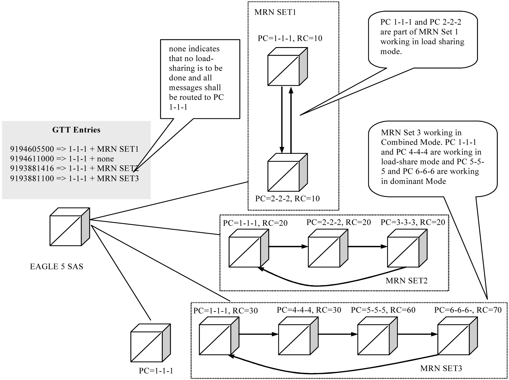
The Flexible Intermediate GTT Load-Sharing feature provides a more flexible way of assigning Load-Sharing rules amongst Global Title Addresses (GTAs). For example, in the following figure,
GTA=9194605500 could translate to PC=1-1-1 and have a load-sharing relationship with PC=2-2-2.
GTA=9194611000 could also translate to PC=1-1-1, but not have a load-sharing relationship with any other PC.
GTA=9193881416 could also translate to PC=1-1-1, and have a load-sharing relationship with PC=2-2-2 and PC=3-3-3.
In the scenario depicted in the following figure, the Flexible Intermediate GTT Load-Sharing feature routes the post-GTT traffic as follows:
-
GTA=9194605500 is divided equally between PCs 1-1-1 and 2-2-2,
-
GTA=9194611000 is always sent to PC 1-1-1, and
-
GTA=9193881416 is divided equally between PCs 1-1-1, 2-2-2, and 3-3-3.
GTA entry 9193881100 would also translate to PC 1-1-1, but PC 1-1-1, PC 4-4-4, PC 5-5-5 and PC 6-6-6 are working in combined mode i.e. PC 1-1-1 and PC 4-4-4 are working in load share mode and PC 5-5-5 and PC 6-6-6 are in dominant mode. Therefore post-GTT traffic for GTA entry 9193881100 is equally divided between PC 1-1-1 and PC 4-4-4.
Figure 3-1 Organization of PCs in Flexible Intermediate GTT Load-Sharing Feature
Flexible Intermediate GTT Load-Sharing provides the ability to load share between multiple nodes after GT translations when the outgoing (post GTT) message is route-on-GT. The resulting PC value of GTT is looked up in the MRN table. If the translated PC is not found in the MRN table, the message is routed as per existing EAGLE 5 SAS functionality.
The destination point code stored in the MSU will be changed when a load-sharing PC is selected.
The Flexible Intermediate GTT Load-Sharing feature provides the ability to define multiple load-sharing groups in the MRN table where a PC can be shared among different load-sharing sets.
Default MRN Set
Once the Flexible Intermediate GTT Load-Sharing feature is enabled, any existing entries in the MRN Table become part of a default MRN Set. In addition, all existing GTA translations in the GTT Table that have a routing indicator (ri) equal to GT are assigned a default MRN Set.
Flexible Intermediate GTT Load-Sharing provides flexible load-sharing for translations defined in GTT Tables but not MPS-based tables. Since MPS-based features do not support an MRN Set Id, to be able to take advantage of the Flexible GTT Load-Sharing functionality, MPS-based features need to be modified. Until all MPS-based features are converted and able to use Flexible GTT Load-Sharing, a default MRN Set is used to provide the necessary support.
The default MRN Set consists of multiple load sharing groups of PCs that allow both GTT features and MPS-based features to run in parallel. MPS-based features are limited to using ONLY the default MRN Set. GTT features can be provisioned to use the default MRN Set as well. To operate on entries in the default MRN Set, the user must specify default as the value of the MRN Set in the GTA translation.
The default MRN Set consists of multiple load-sharing groups of PCs as shown in the following figure.
Figure 3-2 Concept of Default MRN Set

None MRN Set
As mentioned earlier, once the Flexible Intermediate GTT Load-Sharing feature is enabled, any existing entries in the MRN Table become part of a default MRN Set. All existing GTA translations in the GTT Table that have a routing indicator equal to GT (ri= gt) are assigned a default MRN Set. This assignment to a default MRN Set in the GTA translation is irrespective to whether the translated PC exists in any MRN Set. If no load sharing is desired, the user must manually change the GTA translation to MRN Set equal to None. (mrnset=none).
Load-Sharing Modes
There are three possible load-sharing modes in an MRN Set.
-
Dominant
-
Load-Share
-
Combined Dominant/Load-Share
The mode that gets applied to an MRN Load-Sharing Set is determined by the relative cost of the PCs.
Dominant Mode
Table 3-1 MRN Table (MRN Set in Dominant Mode)
| MRN Set ID | PC | Relative Cost | Next Alternate Point Code |
|---|---|---|---|
|
1 |
1-1-3 |
15 |
1-1-1 |
|
1 |
1-1-1 |
20 |
1-1-2 |
|
1 |
1-1-2 |
30 |
1-1-3 |
Global Title to the Lowest Cost PC
If an MSU comes in with TT =10, GTA= 9194605212, then as shown in the following table:
-
If PC 1-1-3 is available, the MSU is routed to 1-1-3, which is the preferred PC.
-
If PC 1-1-3 is not available but PC 1-1-1 is available, the MSU is routed to PC 1-1-1, which is the next preferred PC.
-
If PC 1-1-3 and PC 1-1-1 are not available but PC 1-1-2 is available, the MSU is routed to PC 1-1-2, which is next preferred PC.
-
If all PCs are unavailable in the MRN set, the message are dropped. .
Table 3-2 GT Translation Table
| Translation Type | GTA | PC | MRN Set Id |
|---|---|---|---|
|
10 |
9194605000 to 9194605499 |
1-1-3 |
1 |
|
10 |
9194605500 to 9194605599 |
1-1-1 |
1 |
|
10 |
9194605600 to 9194605799 |
1-1-3 |
2 |
|
10 |
9194605800 to 9194606000 |
1-1-1 |
3 |
Global Title to a Higher Cost PC
It is possible that the result of a GT translation is not the same as the lowest cost PC. This PC is still the preferred PC and will be selected if it is available. If the preferred PC is not available then, the available PC in the list of alternate PCs with the next higher relative cost is selected for routing.
If an MSU comes in with TT=10, GTA=9194605555 then as shown in the following table:
-
If PC 1-1-1 is available, the MSU is routed to PC 1-1-1, which is the preferred PC for this translation.
-
If PC 1-1-1 is unavailable but 1-1-2 is available, the MSU is routed to PC 1-1-2, which is the next preferred PC.
-
If PCs 1-1-1 and 1-1-2 are not available but PC 1-1-3 is available, the MSU is routed to PC 1-1-3, which is the next preferred PC.
-
If none of the PCs are available, the message is dropped.
Load-Share Mode
An MRN Load-Sharing Set is in Load-Share Mode if each PC in the group has the same relative cost. The EAGLE 5 ISS evenly distributes the translated MSUs to each of the PCs listed in the following table.
-
If one or more of the PCs are not available, the EAGLE 5 ISS evenly distributes the MSUs to the remaining PCs in the group that are available.
-
If none of the PCs in the group are available, the message is dropped
Table 3-3 MRN Table (MRN Set in Load-Share Mode)
| MRN Set ID | PC | Relative Cost | Next Alternate Point Code |
|---|---|---|---|
|
2 |
1-1-3 |
10 |
2-2-1 |
|
2 |
2-2-1 |
10 |
2-2-2 |
|
2 |
2-2-2 |
10 |
1-1-3 |
Combined Dominant/Load-Share Mode
A group of PCs is in Combined Load-Share/Dominant Mode when
-
at least two of the PCs have the same relative cost and,
-
another PC, or group of PCs, in the MRN Set has a different relative cost.
Table 3-4 MRN Table (MRN Set in Combined Load-Share/Dominant Mode)
| MRN Set | PC | Relative Cost | Next Alternate Point Code |
|---|---|---|---|
|
3 |
1-1-1 |
10 |
3-3-1 |
|
3 |
3-3-1 |
10 |
3-3-2 |
|
3 |
3-3-2 |
20 |
3-3-3 |
|
3 |
3-3-3 |
20 |
1-1-1 |
If an MSU comes in with TT 10, GTA 9194605999 then as shown in the following table:
If both PC 1-1-1 and PC 3-3-1 are available, the EAGLE 5 ISS will evenly distribute MSUs for TT=10 and GTA=9194605999 to PC 1-1-1 and PC 3-3-1.
If PC 1-1-1 is not available, the EAGLE 5 ISS will send all MSUs to PC 3-3-1.
If both PC 1-1-1 and PC 3-3-1 are not available, the EAGLE 5 ISS will evenly distribute the MSUs to PC 3-3-2 and PC 3-3-3.
If all PCs in this MRN Set are unavailable, the message is dropped.
Handling of SCCP Class 1 Messages
If the In-Sequence Class 1 SCCP option is ON, MSUs are routed to the PC that results from the GTT regardless of the mode of the MRN Set, and the sequence of the MSUs is maintained. If that PC is down, then the MSUs are routed to the next preferred node in the MRN Set.
If the In-Sequence Class 1 SCCP option OFF, the EAGLE 5 ISS load-shares the MSUs depending on the mode of the MRN Set, and the sequence of the MSUs is not maintained.
Activation
The Flexible GTT Load-Sharing feature requires activation via a feature access key (FAK). This feature key applies to all flexible GTT loading functionality. However, Flexible Intermediate GTT Load-Sharing is a separate feature within the EAGLE 5 ISS. To access the functionality of this feature, both the Flexible GTT Load-Sharing FAK and the Intermediate GTT Load-Sharing FAK must be on.
Note:
Currently flexible load-sharing functionality only applies to GTT tables. MPS-based features are NOT be able to take advantage flexible load-sharing.
Hardware Requirements
No new hardware is required for this feature.
The Flexible GTT Load-Sharing Feature requires a DSM card running the VSCCP application.
The Flexible GTT Load-Sharing Feature is not supported on TSM cards running the SCCP application.
Limitations
The MRN table has a maximum of 6000 MRN entries.
The Flexible Intermediate GTT Load-Sharing feature is not supported on TSM cards running the SCCP application.
Flexible GTT Load-Sharing feature does not support SEAS.
3.10 Flexible Link set Optional Based Routing (Release 41.0)
The Flexible Link set Optional Based Routing (FLOBR) feature allows GTT routing to be based on the incoming linkset. Messages that encounter GTT are routed based on the incoming linkset of the original MSU. MSUs that are generated by the EAGLE 5 ISS use a separate set of GTT selector entries.
The FLOBR feature also allows full customization of the GTT routing hierarchy. If flexible routing is used, then a predetermined routing hierarchy is not necessary. The GTT routing translation can link to any GTT set as long as the GTT set has a different set type.
The capacity of the GTT selector table is increased to support 100,000 GTT selectors.
3.10.1 Feature Control Requirements
Feature control requirements for the FLOBR feature include:
- FAK for part number 893-0277-01
- The Enhanced GTT feature must be turned on before the FLOBR feature can be enabled.
- A temporary FAK cannot be used to turn on the feature.
- After the feature is turned on, it cannot be turned off.
3.11 Flexible Point Code Formatting (Release 26.0)
Description
The Flexible Point Code Formatting feature provides the customization and flexibility of the EAGLE point code provisioning system to meet the needs of ITU-N customers who required a specific ITU-N point code format. The one commonalty of the all ITU-N point codes is that the point code is stored in a 4-byte field in our database (14 bits used for ITU point codes). This value does not change, no matter how it is displayed or input on the EAGLE.
For example, suppose the EAGLE is deployed to 5 different regions for ITU-N customers in Europe. Each region has its own way of viewing point codes in its private network. One region may wish to distribute its point codes in a format such as A-B, where A ranges from 1 to 1024, and B ranges from 1 to 16. Other regions may wish to use an A-B-C-D point code format. The following table provides examples of how these point codes might be used in different regions.
Table 3-5 Sample ITU-N Point Codes
|
Region 1 |
Region 2 |
Region 3 |
Region 4 |
Region 5 |
|
1000-1 |
5-5-5-1 |
3-8-3 |
4000 |
1000-1-1 |
|
1000-5 |
3-1-1-0 |
1-7-1 |
16000 |
1000-0-1 |
|
1000-6 |
5-2-1-3 |
1-100-1 |
12000 |
800-1-0 |
Upgrade Considerations
All EAGLEs that are upgraded to software that includes the Flexible ITU-N Point Code Feature must have the NPCFMTI parameter in the STPOPTS table set to a system default of 14-0-0-0.
Limitations
It is important to note that this feature does not provide the ability to support point codes that are not 14 (ITU) or 24 (ANSI) bits in length, and has no impact on EAGLE SS7 message processing. Also, it does not apply to gateway screening commands and output, due to the way that GWS was originally designed to take into account the point code format.
3.12 FLOBR Enhancements (Release 42.0)
The Flexible Linkset Optional Based Routing (FLOBR) feature is enhanced to provide the following functionality:
- Fall-back to GTT after EPAP-based Relay Services
Global Title Translation (GTT) can be performed on an MSU that is relayed to another destination based on routing data obtained from the EPAP database/PPSOPTS table by an EPAP-based service. GTT for Service Related MSUs is performed on a service selector basis. Each supported service selector can be configured to indicate whether GTT is required after service execution is complete. The MNP, GFLEX, GPORT, SMSMR, IDPR, INPMR, and TTR service selectors are supported.
- GTT/TT Commands allowed with EGTT
The
ent/dlt/rtrv-ttandent/chg/dlt/rtrv-gttcommands are supported for GTT simple entries (entries that have not been modified by enhanced GTT processes) independently of the enabled GTT features. - CdPA SSN for GTT Routing
GTT routing can be performed based on Called Party (CdPA) Subsystem Number (SSN) translations when the FLOBR feature is turned on.
- DPC for GTT Routing
The MTP Destination Point Code (DPC) can be considered as part of the routing criteria for GTT Routing.
- Use of the same GTT set types in a Translation Search
When performing a translation using FLOBR processing, lookup can occur in the same GTT set type up to 7 times during a search. The same set name cannot be repeated in a single GTT search.
- Feature independence of the TST-MSG tool
The TST-MSG tool can be used when any GTT feature is turned on.
3.12.1 Feature Control Requirements
- The GTT feature bit must be turned on before the Fall-back GTT functionality can be provisioned, the GTT commands can be used with EGTT, and the TST-MSG tool can be used with any GTT feature.
- The FLOBR feature (Part Number 893-0277-01) must be turned on before the DPC for GTT Routing, CdPA SSN for GTT Routing, or Use of the Same GTT Set Types in a Translation Search functionality can be provisioned.
3.13 Force Change of an Assigned Password at First Login (Release 21.0)
When a password is assigned to a user by the system administrator with either the ent-user or chg-user commands (the pid=yes parameter must be specified with the chg-user command to change the user’s password), that user is required to change the password when they first login to the EAGLE. If the user does not change the password, the login session is rejected.
As part of the password verification process, a check is performed to make sure that the user has changed the password and did not re-enter the current password as the new password.
3.14 FTP Retrieve and Replace (Release 29.0) (IP7 Release 7.0)
Description
Note:
The FTP Retrieve and Replace feature provides configuration and data transfer support on the EAGLE for the FTP-based Table Retrieve Application (FTRA), which resides on a customer-provided, Windows-based PC or Unix Workstation. FTRA will be available separately. In order to use FTRA, the IP User Interface: Telnet Support feature (IP UI) must be enabled . When the IP UI feature is enabled in Release 29.0, the functions provided by the FTP Retrieve and Replace feature become available for communication between the EAGLE and FTRA.
The FTP Retrieve and Replace feature adds a new and expanded retrieve and replace capability to the IP User Interface Telnet feature.
This feature utilizes:
-
GPSM-II card as the hardware platform for OAM.
-
IPSM card as the hardware platform for the IPS GPL.
-
FTP-based Table Retrieve Application (FTRA) software running on a Unix or Windows-based PC platform connected to the IPSM card.
The FTP Retrieve and Replace Feature provides the following new capabilities:
-
Enhanced retrieve capabilities of EAGLE table data, whereby the application will retrieve table data transparently upon request by the user, and later will convert, on demand, to a comma separated variable (.csv) file.
-
Enhanced input capabilities of EAGLE table data, supporting input of script files containing scripts created by the user. The transfer of data to the EAGLE is transparent to the user.
-
A much faster and more reliable retrieval and input capability.
-
Validating data prior to input and identifying the data at issue.
The FTP Retrieve and Replace feature uses FTP commands to transfer relevant parts of the EAGLE STP OA&M database to a Unix or Windows-based PC, where a new Tekelec-developed Java-based application is running. The application provides features to input changes to table data.
The IPS GPL is memory-mapped such that the FTP area can handle the largest database file on the OA&M. The following figure illustrates the feature in relation to the system and customer's network.
Figure 3-3 FTP Retrieve and Replace

Hardware Requirements
This feature requires IPSM (GPSM-II-based) hardware with at least 1 GB of RAM (i.e., DSM 1GB with the IPS GPL [IPSM].
Caution:
Never install or initialize MCAP cards in MASP slots 1113 and 1115 after features that require GPSM-II cards are provisioned. Attempting to initialize MCAP cards with GPSM-II features provisioned will cause a system outage. Before replacing an existing GPSM-II card in a MASP slot (1113 and 1115) contact Tekelec Customer Service.
The application requires a UNIX workstation equipped with the following:
-
Operating System - Solaris 7
-
Processor speed - 500 MHz
-
RAM - Minimum 512 MB
-
Disk Space - Minimum 10 GB
-
CD-ROM drive
-
10/100BaseT Ethernet connection to the LAN
-
Static IP addressing
-
Java Runtime Environment (JRE) 1.4.0 or later
The application requires a Windows PC workstation equipped with the following:
-
Operating System - Windows 98 or later with Win32 API
-
Processor speed - Pentium III, 750 MHz or faster
-
RAM - Minimum 128 MB
-
Disk Space - Minimum 500 MB free + 500 MB free per STP
-
CD-ROM drive
-
10/100BaseT Ethernet connection to the LAN
-
Static IP addressing
-
Java Runtime Environment (JRE) 1.4.0 or later
3.15 FTRA 2.1 Compatibility with EAGLE 31.3 (Release 31.3)
The FTRA Release 2.1 provides FTRA compatibility with EAGLE 31.3. There are no new features or functionality in Release 2.1.
3.16 FTRA 2.2 Compatibility with EAGLE 31.6 (Release 31.6)
The FTRA Release 2.2 provides FTRA compatibility with EAGLE 31.6. The following changes have been made in FTRA 2.2 to support features new to Release 31.6:
-
ASM Obsolescence - Data field of card type "ASM” changed to "TSM” for rtrv-card.
-
IPGWx TPS Control and System-wide IPGWx TPSñ New data fields MATELSN, IPTPS, LSUSEALM, SLKUSEALM added in rtrv-ls.
-
Support G-Flex at 1700 TPS per DMS ñ New data field ANSIGFLEX added in rtrv-stpopts.
-
TDM Global Timing Interface - New data fields HSCLKSRC and HSCLKLL added to support global timing interface in rtrv-stpopts.
3.17 FTRA Dependencies on EAGLE (Release 46.0)
The FTRA Dependencies on EAGLE feature removes all the FTRA dependencies on EAGLE, such as validation of rtrv-gpl in FTRA and generation of stp.csv by FTRA.
3.18 Gateway Screening Stop Action - De-encapsulate (Release 46.0)
The Gateway Screening Stop Action - De-encapsulate feature adds the capability to de-encapsulate a re-directed message from a remote EAGLE and provide all of the features and functionality to the encapsulated MSU as if the MSU were received without any SCCP encapsulation.
3.19 Gateway Screening Stop Action - Duplicate and Route (Release 46.0)
The Gateway Screening Stop Action - Duplicate and Route feature allows users to duplicate and forward ISUP messages selectively to another monitoring system where analysis can be performed to identify potential spam or robo-call scenarios. The Gateway Screening Stop Action - Duplicate and Route feature provides this capability of selective forwarding of MSU's to another network element.
3.20 Gateway Threshold Exceeded Notification (Release 22.0)
A notification message is produced to alert the user that excessive traffic is occurring on a gateway linkset or an excessive number of MSUs are being discarded on a gateway linkset. When either of these conditions occur, new UIMs are sent to the EAGLE terminals.
UIM 1154 - Gateway Arrival Threshold Exceeded - MSU reception threshold exceeded
RLGHNCXA03W 97-06-07 16:28:08 EST Rel 22.0.0
0018.1154    SYSTEM       INFO MSU reception threshold exceeded
             LSN=A1234567 REJ=199     RECV=5200   INTRVL=05
             Report Date: 97-06-07  Time: 16:27:19
UIM 1155 - Gateway Discard Threshold Exceeded - MSU discard threshold exceeded
RLGHNCXA03W 97-06-07 16:28:08 EST Rel 22.0.0
0018.1155    SYSTEM       INFO MSU discard threshold exceeded
             LSN=A1234567 REJ=199     RECV=5200   INTRVL=05
             Report Date: 97-06-07  Time: 16:27:19
The message REPT-GTWYACT is sent to the SEAS interface when these conditions occur.
The term excessive is defined by two values.
-
The number of MSUs discarded on the gateway linkset.
-
The number of MSUs received on the gateway linkset.
These values measured over a user configurable period of time. If either of these values are exceeded within the specified period of time, then this notification occurs.
The threshold at which these UIMs are generated can be configured by the user on the EAGLE terminal with the set-gtwy-acthresh command.
Parameters
The set-gtwy-acthresh command uses these parameters.
:lsn = the name of the link set
:rej = the number of MSUs discarded on the gateway linkset threshold. The values for this parameter range from 0 to 999999
:recv = the number of MSUs received on the gateway linkset threshold. The values for this parameter range from 0 to 999999
:intrvl = the time interval, in minutes, during which the counts for the rej and recv parameters are made. The values for this parameter are 5,10,15, 20, and 30.
The current values for these thresholds can be displayed on the EAGLE terminal with the rtrv-gtwy-acthresh command. The following is an example of the rtrv-gtwy-acthresh command output.
Output Example
RLGHNCXA03W 97-06-07 08:50:12 EST Rel 22.0.0
LSN         REJ        RECV        INTRVL
WY644368    10         1000        10
WY234456    25         2000        20
LN123445    0          0           0
LN123556    25         2500        30
OP239900    0          0           0
These thresholds can also be configured on the SEAS interface with the SET-GTWY-ACTHRESH command function and displayed on the SEAS interface with the RTRV-GTWY-ACTHRESH command function.
The counts for the number of MSUs discarded and received on the gateway linkset are collected in the 5 minute measurement collection. These counts do not appear on any measurement reports, but are collected to support this feature. These counts track the two values that need to be monitored.
This feature no longer allows the 5 minute measurement collection to be stopped with the EAGLE’s chg-meas:collect=off command. The 5-minute measurement collection still occurs, but no values are written to disk and no reports are produced.
3.21 General Purpose Service Module-II (GPSM-II) for MCAP Slot (Release 28.0)
Description
The Enhanced MCAP, otherwise known as the GPSM-II (General Purpose Service Module, P/N 850-0622-01) for MCAP Slot, is designed to provide better OAM task performance.
Future applications and table expansions will require increased performance across the IMT bus interface, both to and from the Maintenance and Administration Subsystem (MAS). To help meet this need, the GPSM-II card incorporates a DCM design for the OAM functionality on the EAGLE.
GPSM-II is required for supporting the EAGLE Support for Integrated Sentinel feature via the Time Slot Counter (TSC) Synchronization feature.
Refer to the NSD Hardware Manual for the current hardware description.
New Hardware Required
The GPSM-II feature requires the new GPSM-II (OAM) card described above); no additional hardware is required.
Caution:
Never install or initialize MCAP cards in MASP slots 1113 and 1115 after features that require GPSM-II cards are provisioned. Attempting to initialize MCAP cards with GPSM-II features provisioned will cause a system outage. Before replacing an existing GPSM-II card in a MASP slot (1113 and 1115) contact Tekelec Customer Service.
The TSC Synchronization feature requires the new GPSM-II EAGLE® hardware equipped with the new TSC Synchronization hardware to support it. Time Slot Synchronization is an existing option for the EAGLE that allows all cards in the system containing a Time Slot Counter to synchronize with each another. The ability to have synchronized timing between cards is useful in applications such as system-wide message time stamping.
Upgrade Considerations
The GPSM-II feature allows the existing OAM functionality to operate on a GPSM card or MCAP card. In addition, the EAGLE will also support inserting an MCAP or GPSM card in the control shelf as an OAM card, even if the OAM card that is already inserted does not match the OAM card that is being inserted. This functionality is needed to support upgrade where the hardware is in transition. It is assumed that an EAGLE with an MCAP and a GPSM in OAM card slots 1113 and 1115 is a transitional state.
Consequently, software modification of the one-command upgrade function is necessary to support some requirements. Upgrade command support for the inhibiting of the standby OAM and upgrade of the board Flash memory is required.
3.22 G-Flex C7 Relay (Release 26.2)
Description
G-Flex optimizes the use of subscriber numbers and number ranges by providing a logical link between any MSISDN/MIN/MDN and any IMSI, as well as between any subscriber number and any HLR. This feature allows subscribers to easily be moved from one HLR to another.
Note:
This feature applies to any GSM or IS-41, ITU, or ANSI mobile network. In the following text, the term DN is used to indicate MSISDN numbers, MINs, or MDNs. Also, the term subscriber number is used to indicate DN and/or IMSI.
It also allows each HLR to be filled to 100% of its capacity by allowing subscriber number ranges to be split over different HLRs, and individual DNs/IMSIs to be assigned to any HLR. Another benefit is that subscriber number routing data is not required to be maintained in all MSCs in the network.
The initial version of G-Flex, as defined in this document, applies to routing to HLRs only. In the future, G-Flex may be expanded to include routing to other intelligent devices, such as SCPs (Service Control Points) and VMSCs (Voice Mail Service Centers), depending upon market needs.
G-Flex is optional on the EAGLESTP, and can be turned on (but not turned off) via a feature bit. G-Flex and North American LNP are mutually exclusive on an EAGLE node.
Refer to the Features Manual - G-Flex for the current information on this feature.
Upgrade Considerations
EAGLE Database
The EAGLE upgrade process is responsible for copying new TDM resident G-Flex tables from the upgrade removable cartridge to the newly formatted fixed disks. The G-Flex feature bit should not be turned on prior to or during an upgrade of an existing EAGLESTP.
EAGLE STP Audit
The EAGLESTP audit is designed to recognize when it is in upgrade mode, and will not attempt to do any activity that requires access to new G-Flex tables, since they will not be present until the upgrade has completed.
In order to convey G-Flex audit-detected errors to the active OAM, space in the common maintenance block header must be identified. In order to prevent false alarms during the upgrade, the revision level of the maintenance block has been redefined. Existing code that examines maintenance blocks will not interpret them if the system is in upgrade mode and the revision level in the received maintenance block is not at the expected value.
EAGLE Maintenance
During upgrade, the rept-stat-epap command output may not reflect the current state of the GSM system.
Hardware Requirements
This feature requires the MPS Hardware System.
Limitations
-
An E.214 number received by the G-Flex™ C7 Relay must first be converted to an E.212 number before searching the G-Flex database. If the original E.212 number was truncated to form the E.214 number, the full original E.212 number cannot be recovered, and G-Flex™ will not work properly.
-
No overload controls are required above and beyond existing EAGLE lower level mechanisms (e.g. for MTP congestion, etc.).
-
This initial version of the G-Flex™ C7 Relay only supports routing of messages to a single network node for a particular subscriber. For example, an individual subscriber cannot have some messages routed to his HLR, and other messages routed to a separate Authentication Center (AuC). In this example, if the AuC is co-located with the HLR, then this version of G-Flex™ will work. The G-Flex™ design allows for expansion to include routing to multiple network elements (corresponding to multiple services) for the same subscriber.
-
Messages routed by G-Flex™ cannot undergo ANSI-ITU conversion.
3.23 G-Flex MAP Layer Routing (Release 38.0)
The G-Flex MAP Layer Routing (MLR) feature allows subscriber digits to be obtained from either the SCCP layer or the MAP layer of a message during G-Flex database lookup. This ability resolves the issue of truncation of digits by the mobile switching center (MSC) that may occur in the SCCP layer.
This feature applies to GSM MAP Update_Location, GSM MAP Send_Authentication_Information (SAI), and GSM Send_Parameters messages. CdPA digits from the SCCP layer are used to route all other MAP messages.
Note:
The feature supports Send_Parameters messages only if the message contains the IMSI parameter.As part of this feature, the G-Flex feature is converted from a feature bit to a FAK and part number.
3.23.1 Feature Control Requirements
The G-Flex MAP Layer Routing feature has the following feature control requirements:
- The G-Flex feature must be enabled and turned on (FAK for part number 893-0219-01) before the G-Flex MLR feature can be enabled.
- The G-Flex MLR feature requires a FAK for part number 893-0217-01
- If the ansigflex option in
chg-stpoptscommand is turned on, then the feature cannot be enabled. - A temporary FAK cannot be used to enable the G-Flex or the G-Flex MLR features.
- If the G-Flex feature is turned on with the feature bit before upgrade occurs, then the feature is automatically enabled and turned on with the FAK after upgrade.
- The G-Flex and G-Flex MLR features cannot be turned off after being turned on.
3.24 G-Flex MAP Layer Routing (Release 43.1)
For G-Flex MAP Layer Routing message processing controlled by the MAPLYRRTGON option, the MAPLYRRTGON option must be set for the operation code in the incoming message and SCCP CdPA NP=E.214, if NP is present.
The following conditions are no longer required for the G-Flex MAP Layer Routing feature to be applied when the message processing is controlled by the MAPLYRRTGON option:
-
The length of the MCC+MNC (Mobile Country Code + Mobile Network Code) in the resulting E.212 IMSI number must be greater than the length of the CC+NDC (Country Code+Network Destination Code) in the E214 MGT number that is converted to the E212 IMSI number. The maximum length of the SCCP CdPA is 15 digits.
If the MCC+MNC length is greater than the CC+NDC length and CdPA is 15 digits, then after E.214 MGT to E.212 IMSI conversion, the resulting number of digits is greater than 15. The last digits may be truncated; in this case, IMSI digits can be taken from the MAP layer.
-
The CdPA GTI=2
or
The CdPA GTI=4 and the SCCP CdPA length is 15 digits.
3.25 G-Flex MAP Layer Routing support for ATI using MSISDN (Release 42.0)
The G-Flex MAP Layer Routing support for ATI using MSISDN feature enhances the existing G-Flex MAP Layer Routing (G-Flex MLR) feature by providing the option to route AnyTimeInterrogation (ATI) messages using the Mobile Subscriber ISDN Number (MSISDN) from the MAP layer of the incoming message.
If the option is provisioned, then the MSISDN is converted to International Format and used for number conditioning and RTDB look up. If the option is not provisioned or if the MSISDN number is not present in the MAP layer, then normal G-Flex routing using the SCCP called party number (CdPA) is performed.
3.26 G-Flex MLR Support for Additional OpCodes (Release 43.0)
The existing G-Flex Map Layer Routing (G-Flex MLR) feature (Part Number 893-0217-01) is enhanced to support additional MAP Operations:
Table 3-6 New MAP Operations Supported by the G-Flex MLR Feature
| MAP Opcode | MAP Message Description | MAP Operation Name |
|---|---|---|
| 10 | Register Supplementary Service | registerSS |
| 12 | Activate Supplementary Service | activateSS |
| 13 | Deactivate Supplementary Service | deactivateSS |
| 14 | Interrogate Supplementary Service | interrogateSS |
| 15 | Authentication Failure Report | authenticationFailureReport |
| 57 | Restore Data | restoreData |
| 59 | Process Unstructured SS Request | processUnstructuredSS-Request |
| 66 | Ready for Short Message | readyForSM |
| 67 | Purge Mobile Subscriber | purgeMS |
| 85 | Send Routing Information for LoCation Service | sendRoutingInfoFor LCS |
This enhancement also allows the G-Flex MLR feature to use the MSISDN from the MAP layer if the IMSI is not available for routing Process Unstructured SS Request and sendRoutingInfoForLCS messages.
3.27 Global Option for Connect on INP Query Response (Release 35.0)
Description
The Global Option for Connect on INP Query Response feature adds a global INP option that indicates whether the EAGLE 5 ISS is to send “Connect” or “Continue” messages when an IDP message is received for INP service, the DN digits match, and the HLR ID is present.
Note:
The Connect INP option does not affect the INP Message Relay service.Hardware Requirements
The Global Option for Connect on INP Query Response feature has no hardware requirements.
Limitations
The Global Option for Connect on INP Query Response feature has no limitations.
3.28 Global Title Modification (Release 28.1) (IP7 Release 6.0)
Description
This feature allows the user to modify any part of the Global Title in the outgoing message, other than Encoding Scheme, after GTT has been performed. A new Translation Type (TT), Numbering Plan (NP), and/or Network Address Indicator (NAI) value can be specified. Also, a specified number of leading digits of the GT address can be deleted, and/or a set of specified digits can be added to the beginning of the GTA. This is all defined on a per-entry (i.e. GTA) basis.
Refer to the Database Administration Manual - Features for current details of this feature.
Hardware Requirements
No new hardware is needed to support this feature.
Upgrade Considerations
The EAGLE provides an upgrade conversion for customers using the Interim GT Modification feature supplied in Release 26.0. Database conversions are handled during upgrade.
3.29 Global Title Translation (GTT) (Release 20.0)
The global title translation (GTT) subsystem of the EAGLE can support the following level of activity.
-
850 messages per second
-
21,000 global title translations per second per system
The maximum number of entries in the global title translation table is 270,000 entries. It is possible to enter all 270,000 entries under one translation type. However, the system works most efficiently when there are 65,536 or fewer GTT entries per translation type. While there is no mechanism to limit the number of GTT entries to fewer than 65,537 per translation type, the performance of the GTT subsystem is not guaranteed when more than 65,536 translations are entered for a single translation type.
3.30 G-Port MNP (Release 26.2)
GSM Mobile Number Portability (G-Port) provides mobile subscribers the ability to change the GSM subscription network within a portability cluster, while retaining their original MSISDN(s).
Throughout the world, an increasing number of governments are mandating that telecommunications network operators support service provider number portability. Service provider portability allows a consumer to change service providers while retaining his phone number. Service provider portability is intended primarily to promote competition among service providers. It applies to both wireline and mobile phone networks. In particular, this feature is focused on service provider portability in GSM (Global System for Mobile communications) networks.
While the advent of number portability is good news for consumers, it presents many challenges for network operators. G-Port MNP (Mobile Number Portability) minimizes those challenges for GSM network operators, while enabling them to efficiently meet their regulatory obligations.
For current details of this feature, refer to the Features Manual - G-Port.
3.31 G-Port MNP Circular Route Prevention (Release 28.1)
Description
In some cases, networks may have incorrect number portability data for a subscriber. For example, a subscriber may have ported from network A to network B. Network A has the correct routing information, indicating the subscriber now belongs to network B. However, network B may have incorrect routing information indicating that the subscriber still belongs to network A. In this case, network A routes the call to network B, based on its portability data, but network B routes the call back to network A, based on its incorrect data. This behavior results in a circular route.
This feature provides an option to prevent this from happening.
For current detail on this feature, refer to the Features Manual - G-Port.
Hardware Requirements
No new hardware is needed to support this feature.
Upgrade Considerations
The EAGLE upgrade process is only responsible for copying new GSM tables from removable cartridge to the newly formatted fixed disks.
3.32 G-Port SRI Query for Prepaid (Release 35.2)
G-Port SRI Query for Prepaid Detailed Description
The G-Port SRI Query for Prepaid feature enables the EAGLE 5 ISS to provide portability information to a Service Control Point (SCP) database. This information enables the database to determine the network used by a called subscriber.
- translation type (TT)—The TT of the called party (CdPA)
- originating point code (OPC)—The OPC from the message transfer part (MTP) layer
- global title address (GTA)—The GTA of the calling party (CgPA)
These values are used to determine whether an SRI should receive G-Port SRI Query for Prepaid service or normal G-Port SRI service.
If the G-Port SRI Query for Prepaid feature is enabled and turned on, an incoming SRI’s TT, OPC, and GTA values are compared against the values in the GSERV table. If no match is found, or if no values are provisioned in the GSERV table, normal G-Port SRI processing is performed on the message. If a match is found for one or more of the values, the message is treated as a Prepaid Query.
The G-Port SRI Query for Prepaid feature affects only SRI messages. All other messages, including SRI-SM and SRI-GPRS messages, are processed by normal G-Port service, even if the values in those messages match values in the GSERV table.
After an SRI message is identified as requiring G-Port SRI Query for Prepaid service, the EAGLE 5 ISS performs a Mobile Number Portability (MNP) database lookup on the Mobile Station Integrated Services Digital Number (MSISDN). The results of the lookup are returned to the SCP that originated the query.
A TCAP/MAP error specifically related to a decoding error in the SRI MSISDN parameter causes an “Unsupported/Unexpected Data Value” MAP error. All other TCAP/MAP errors cause the message to be relayed to a Home Location Register (HLR), which then returns the appropriate MAP error based on the status of the subscriber (e.g. Unknown, Barred, etc.)
The message relay is based on information in the G-Port MNP database. SCCP level errors cause the return on a UDTS message to the Prepaid SCP.
This feature requires a Feature Access Key and cannot be turned off once it is turned on.
Hardware Requirements
The G-Port SRI Query for Prepaid feature has the same requirements as those required for the G-Port feature.
3.33 G-Port SRI Query for Prepaid Service Portability (Release 41.1)
Service Portability support for the G-Port SRI Query for Prepaid feature allows GRN digits to be used in place of RN digits during construction of Mobile Station Routing Numbers (MSRNs).
Default Routing Number
A Default Routing Number (Default RN) is introduced for the G-Port SRI Query for Prepaid feature. The Default RN option applies to Number Portability, and can be used whether the S-Port feature is on or off. If the S-Port feature is on, then the Default RN applies in cases where Service Portability usage of GRN does not apply for own network subscribers. If the S-Port feature is off, then Default RN digits can be used for own-network subscribers during construction of the MSRN instead of the RN/PT=0 or SP entity associated with the RTDB subscriber entry.
3.34 GR-376 Interface (Release 26.0)
Description
The GR-376 Support feature provides an optional method of data collection from the EAGLE STP. Measurement and reference data is collected with the EAGLE and passed to a supplemental Network Data Collection (NDC) Q adapter function (QAF).
Refer to the Feature Manual - GR-376 for current information on this feature.
Limitations
The following limitations apply to the initial release of the GR-376 Support feature:
-
Explicit retrieval of current data objects is not supported.
-
NDC data recovery is provided only when at least one EMAP originally received the data from an EMDC DCM card. No provision is made in the initial release to recover lost data spanning multiple periods.
-
Other than reference data, no GR-495-specified data storage objects are supported for this release.
-
No notifications are supported in the initial release.
3.35 Group Ticket Voucher (Release 23.0)
Description
This feature is used to control the traffic from the high-speed ATM signaling links to the ASM-SCCP cards and ACMs. The ASM-SCCP cards are used to process messages requiring global title translation. The ACMs are used by the STPLAN feature to send messages selected by the gateway screening feature to a remote host for further processing. The message rate from a single high-speed ATM signaling link can exceed the capacity of a single ASM-SCCP card or a single ACM, so the message traffic is split between multiple ASM-SCCP cards or ACMs.
To determine which card can process the message, each type of message is assigned a group number by the system software.
-
SNM messages - group 1
-
STPLAN messages - group 2
-
SCCP messages - group 3
Note:
Only SCCP messages containing a destination point code that is the EAGLE’s true point code or one of its capability point codes are affected by this feature.
Each card of each card type is assigned a member number by the system software when the card is entered into the database with the ent-card command. This number is not configurable by the user and cannot be displayed with the rtrv-card command. This number is used only internally by the software to identify the cards to the group ticket voucher feature. The member number can range from 0 to 31. The number assigned to the card is the smallest number in the range from 0 to 31 that is not already in use. The STPLAN and SCCP member numbers are assigned independently of each other. The system software does not check the number of ASM-SCCP cards entered into the database, but the system software supports a maximum of 25 ASM-SCCP cards, and a maximum of 30 ACMs. If more than 25 ASM-SCCP cards or 30 ACMs are entered into the database, the member number of the newly entered card is set to 31.
When a signaling link receives an SCCP message or wants to send an STPLAN message to a remote host, it sends a request on the IMT bus to find either an ASM-SCCP card or an ACM (depending on the type of message) that has capacity to handle the message. When a card is found that can handle the message, that card answers the request, informs the requesting signaling link that it can handle the message, and sends in its answer the card’s group number and member number. When the requesting signaling link receives the answer, it translates the card’s group number and member number into the card’s IMT address, then sends the SCCP message or STPLAN message to that IMT address. The request to find the ASM-SCCP card or ACM is referred to as a voucher. The answer to the request is referred to as a ticket. The card that is able to handle the message is referred to as the granter.
Sequenced GTT class 1 traffic on the high-speed ATM signaling links is discarded. The current method for ensuring sequencing in the EAGLE is to use only one ASM-SCCP card at a time for any one signaling link’s stream of sequenced traffic. This imposes a limit on the rate of traffic from any one stream, the speed of an ASM-SCCP card, 850 messages per second. Since the message rate of a high-speed ATM signaling links far exceeds 850, an ASM-SCCP card cannot handle sequenced traffic from a high-speed ATM signaling link.
The following figure shows an example of the operation of the group ticket voucher on the IMT bus. This example is for an SCCP message. The action would be the same for an STPLAN message, but the group number would be different.
-
The ASM-SCCP cards periodically refresh the hardware grant counters (one for each bus) dynamically based on their individual available capacities.
-
When a high-speed ATM signaling link receives an SCCP message, the high-speed ATM signaling link sends a TVG (group ticket voucher) request containing the SCCP message group number (group number 3) to find an ASM-SCCP card that can handle the SCCP message.
-
The request is sent around the IMT bus until it finds an ASM-SCCP card that can handle the message. In this example, members 0 and 1 have no capacity, but member 2 does. Member 2 changes the TVG (group ticket voucher) request, a voucher packet, to a ticket packet, changes the group number of the packet to the ASM-SCCP card’s member number, member 2, and decrements the card’s grant counters for each IMT bus. When member 2’s grant counter reaches zero, that ASM-SCCP card has no more capacity for handling messages and the next available member with capacity begins granting tickets.
-
The ticket packet returns to the high-speed ATM signaling link requesting the service. The high-speed ATM signaling link translates member 2’s group number to the card’s IMT address and sends the SCCP message to that card.
Figure 3-4 Group Ticket Voucher Example

Measurements
MSULOST3
The MSULOST3 measurement is currently used to count the number of MSUs discarded when a card does not have an SCCP assignment or when the linkset-on-hold buffer is full. In Release 23.0, this measurement also counts the number of SCCPMSUs that are discarded by the group ticket voucher feature on the high-speed ATM signaling links. The SCCPMSUs are discarded under these conditions:
-
All Class 1 (sequenced) SCCP traffic sent to the EAGLE.
-
A Class 0 SCCP message for EAGLE arrives when the SCCP group ticket voucher queue is full.
-
A SCCP message in the SCCP group ticket voucher queue is more than 2 seconds old.
The MSULOST3 measurement is displayed in these measurement reports:
SYSTOT-STP - STP system total measurement report
MTCD-STP - STP daily maintenance measurement report
MTCDTH-STP - STP day-to-hour maintenance measurement report
NM-STP - STP network management measurement report
SLANDISC1
The SLANDISC1 measurement is currently used to count the number of MSUs that have not been copied to a remote host because the STPLAN feature is disabled. In Release 23.0, this measurement also counts the number of STPLANMSUs discarded by the group ticket voucher feature on the high-speed ATM signaling links. The STPLANMSUs are discarded under these conditions:
-
An STPLANMSU arrives when the STPLAN group ticket voucher queue is full.
-
An STPLANMSU in the STPLAN group ticket voucher queue is more than 2 seconds old.
The SLANDISC1 measurement is displayed in these measurement reports:
SYSTOT-STPLAN - STPLAN system total measurement report
MTCD-STPLAN - STPLAN daily maintenance measurement report
MTCDTH-STPLAN - STPLAN day-to-hour maintenance measurement report
AVL-STPLAN - STPLAN availability measurement report
3.36 Group Ticket Voucher for SCCP Cards (Release 27.0)
Description
Group Ticket Voucher replaces SCCP Load Balancing as a method of providing SCCP service to LIM cards.
In the current EAGLE implementation, an EAGLE Low Speed LIM (LSL) card is assigned to one SCCP card based on the 16:1 LIM - SCCP Engineering rule via load balancing (LB). The LSL-SCCP assignment may change from time to time, but the engineering rules are maintained at all times. This poses a problem to customers, forcing them to purchase unnecessary hardware (SCCP) so they can meet the engineering rules for LB. The Group Ticket Voucher (TVG) solution currently implemented with HSL/SCCP and HSL/SLAN card assignments alleviates this problem.
The Release 27.0 TVG solution is an extension of the Ticket/Voucher solution to the SNM multicast problem. The Ticket/Voucher concept uses an IMT hardware-based request/grant scheme to provide a flow control solution, which allocates message capacity at hardware speeds. Each grant allows a single message to be sent to the granter. The "group" concept is added to provide for multiple groups of granters, each supporting one particular message type.
Each granter has a group ID that is based on the message type it supports, and will only grant capacity to TVG requests which match its group number. Since the TVG mechanism is designed to provide a one-to-many assignment, there will typically be more than one granter for a group. SNM, by its nature, is the only message type, which will have a single granter (OAM).
Each message type supported by TVG will be assigned to a particular group. A card requesting capacity from a particular group will build a TVG request, and set the group number in the request based on the message type. The group numbers are defined as follows:
-
SNM group 1
-
SLAN group 2
-
SCCP(GTT) group 3
-
REROUTE group 31
In addition to the group number, each granter is assigned a member number, which identifies the granter. The member number is unique within a group, but may be repeated within other groups in the EAGLE. When a granter card grants capacity, it changes the voucher packet into a ticket. It also changes the group number in the packet to its member number. When the TVG request returns to the requester as a ticket, the requester uses the member number along with the group number it saved to look up the IMT address of the granter. The IMT address provides the assignment, which allows the requester to forward the message to the granter.
Upgrade Considerations
LB is supported during upgrade to Release 27.0 only.
Limitations
-
Class-1 GTT traffic on will be allowed, but sequencing will not be guaranteed.
-
The number of TVG requests that can be made per card is a function of the number of cards in the system, and decreases as the number of active cards increase. It is approximately 1/(Nx10-6) for N cards. For a system with 250 IMT addresses it is limited to about 3300 requests/second. This limitation could become a bottleneck if the number of cards on the IMT bus were increased.
3.37 GSM MAP Screening (Release 26.1)
Description
Traditionally, STP message screening has been limited to the MTP and SCCP levels; this has been sufficient to meet operators' needs. However, GSM mobile operators have an increasing need for screening at the Mobile Application Part (MAP) level. This need is driven by advanced network capabilities and proliferating roaming agreements.
New features that require this enhanced screening capability are Inter-operator Short Message Service (SMS) and Any Time Interrogation (ATI). The GSM MAP Screening feature focuses on solving the screening needs associated with ATI, which is defined in MAP version 3. An ATI message allows an external server to interrogate an HLR and obtain information about the location and/or state of a GSM subscriber. It may be desirable to control which external entities can request this information, and what information they can request before allowing the message to pass through to the HLR.
The EAGLE-based solution to this problem is designed to allow the user to provision which MAP SSNs are affected, which MAP op codes to screen, which origination points are allowed, and which error messages to use.
Note:
This feature is only applicable for ITU implementations.
Refer to the Database Administration Manual - Features for current information on this feature.
Hardware Requirements
To meet optimum performance in "worst case" scenarios under heavy traffic conditions, it is recommended that GSM MAP Screening be used in conjunction with high performance SCCP hardware (DSMs). There is, however, no specific requirement restricting GSM MAP Screening to DSM hardware, since a throttling mechanism protects system integrity.
Upgrade Considerations
-
New tables relating to GSM MAP Screening must be created on the upgraded disk.
-
the GSM MAP Screening feature bit should be defaulted to OFF on new upgraded disks.
-
The
STPOPTSvalue ofGSMSDECERRshall bePASSafter upgrade. -
The
STPOPTSvalue ofGSMDFLTshall bePASSafter upgrade.
Limitations
-
Overlapping range entries cannot be provisioned.
-
There is no cross-checking between the individual entry table and the range table when numbers are provisioned. The individual table entries are exceptions to the range table. Thus, if an individual number is provisioned that is already part of a range, automatic splitting of the range entry will not occur. (This is not necessarily a limitation.)
-
Per-server measurements are not provided for range table entries, and no per- server measurement will be pegged when a match occurs in the range table.
-
This feature is applicable only for ITU implementations.
-
A given GTA may be entered in the MAP Screening table only once.
3.38 GSM MAP Screening Duplicate/Forward (Release 29.0)
Description
The GSM MAP Message Duplicate/Forward feature extends the capabilities of GSM MAP Screening by allowing MAP messages to be routed, discarded, duplicated, or forwarded based on the provisioned screening criteria. This gives the EAGLE the ability to offload or copy certain types of MAP messages to an attached processor (such as a SCP) based on the MAP Opcode and/or Calling Party Address.
For these advanced services on MAP messages, targeting messages based only on MTP level screening could lead to many messages being sent to the external platform unnecessarily, possibly impacting the performance of the STP or the external platform. In order to allow a finer granularity in message selection, a method is needed to target only specific MAP messages. Furthermore, it is desirable to achieve this using standard message structures (i.e. SS7).
Refer to the Database Administration Manual - Features for current information on this feature.
Note:
It should be noted that the GSM MAP Message Duplicate/Forward feature is independent of the EAGLE's STPLAN and DTA features. It operates and is provisioned in an entirely different manner than either of these existing features.
Hardware Requirements
No new hardware is needed to support this feature.
Upgrade Considerations
MAP screening tables that were built under the Release 26.1 version of MAP Screening and used the previous default value of NONE for the FORBID parameter will not have that value changed to ALL as a result of an upgrade to this version of MAP Screening. (Those original entries will still have FORBID = NONE, even though new entries after the upgrade will default to FORBID=ALL.)
Limitations
The first implementation of this feature is limited in the following ways:
-
Only works for ITU messages.
-
State and Location are the only GSM Map parameters that screening may forbid.
-
ATI Error responses are the only type of messages that may be sent as a screening rejection response.
-
We do not screen on NP and NAI on a per origination basis, but rather on a per Map Op-Code basis.
-
Measurements are taken on an existing 30-minute schedule and are not reported real-time.
-
During extremely high traffic conditions where 850 messages per second require GSM Map screening on 1 SCCP card, and other SCCP processor intensive features are also in very rare worst case conditions, GSM Map Screening may be throttled to keep SCCP processor utilization below 70%. There will be no alarm or warning when this condition occurs.
3.39 GSM MAP SRI Redirect to Serving HLR (Releases 31.11, 34.0)
Description
This feature provides the capability to resolve the incompatibility introduced by the proprietary implementation of the GSM MAP SRI message. This feature is an extension to the G-Port Mobile Number Portability (G-Port MNP) Protocol. Therefore, the feature is compatible with other MNP enhancement features provided to date, including the "G-Port MNP Circular Route Prevention," "Portability Check for Mobile Originated SMS" and "Pre-paid SMS Intercept" features.
Hardware Requirements
Refer to the hardware baseline.
Limitations
Because this is an ON-only feature, to remove the affect of the feature from call processing, all the VendorID List entries must be deleted.
Note:
This is similar to the behavior of several other protocol features.
3.40 GTT Actions (Release 42.0)
The GTT Actions framework increases the functionality of the Global Title Translation (GTT) and Flexible Linkset Optional Based Routing (FLOBR) features. GTT Actions supports all functionality provided by the Enhanced GSM MAP Screening (EGMS) feature except for screening based on Forbidden Parameters in ATI messages.
Note:
Both GTT Actions and EGMS are supported and can co-exist in the system.The GTT Actions framework consists of three separate features:
- GTT Action - DISCARD – there are three types of discard:
- Discard – discard message with no return error
- UDTS – discard message and send UDTS/XUDTS independently of the value of the Message Handling flag in the MSU
- TCAP Error – return a specified TCAP Error for the opcode
The functionality performed by the GTT Action - DISCARD feature was originally performed by the Origin-based SCCP Routing (OBSR) feature. All entries that were previously provisioned using the OBSR feature will be converted to a GTT Action and Action Set.
- GTT Action - DUPLICATE
Routes a copy of the message to a specified duplicate node. The original message is always routed based on GTT/DB data. A copy of the message is routed to a specified duplicate node if the node is available.
- GTT Action – FORWARD
Routes the original message to a specified forward node instead of the destination indicated by the GTT/ DB data. If the Forward node is not available, a configurable default action can be used. This action could result in an error response (TCAP Error or UDTS), silent discard, or routing based on default GTT/DB data.
The GTT Actions framework allows the creation of a GTT Action Set, which is a list of actions that are performed on a message. A GTT Action ID is used to define the action and its characteristics.
The GTT Actions framework also provides the following capabilities:
- Advanced GTT Modification Enhancements
Data, including Calling Party data, used to configure the Advanced GTT Modification (AMGTT) feature is maintained in a new GT Modification (GTMOD) table.
The AMGTT feature is also enhanced to allow deletion of a trailing 0 in the Global Title Address (GTA) during GTT modification if the conversion from GTI(x)=2 to GTI(x)=4 occurs. Encoding scheme (ES) calculations are performed on the remaining digits after the 0 is deleted.
- Non-overlapped GTT Selectors
ITU GTT selectors (i.e ITU-I, ITU-N, ITU-N24, ITU-I Spare and ITU-N Spare) with different domains can be provisioned for the same GTI value and translation type (TT) independently.
- Per-Path Measurements
Per-Path measurements, the equivalent of the EGMS Per-Path measurements, can be performed by GTT. These measurements provide counts for GTT Actions that match a pre-defined combination of CgPA GTA, CdPA GTA, and Opcode values. This functionality is not specific to FLOBR or GTT Actions, but can be specified for any GT translation. If CdPA-only GTT is the only service turned on, having per-path measurements is not applicable, since there is no searching on CgPA or Opcode.
- Reference Count for GTTSETs
The response of the
dlt-gttsetcommand is enhanced by maintaining an internal reference count for each GTTSET. When a GTTSET is referenced or de-referenced, the reference count for that GTTSET is incremented or decremented by 1. - Support of xlat=none Translations
A GT entry containing GTT Action or GT Modification data can be provisioned when translation data is not present. This ability also allows loadsharing of message-relayed EPAP-based features. If xlat=none is provisioned, then both an MRN set and a MAP set can be provisioned against the translation.
- Unique GTT Selectors
GTT Selectors with ITU-I Spare and ITU-N Spare domains can be provisioned using the
ent/chg/dlt/rtrv-ttandent/chg/dlt/rtrv-gttselcommands.
3.40.1 Feature Control Requirements
- A FAK for the desired Part Number:
- GTT Action - DISCARD: 893-0275-01
- GTT Action - DUPLICATE: 893-0276-01
- GTT Action - FORWARD: 893-0375-01
- The Enhanced GTT (EGTT) feature bit must be turned on before any of the GTT Action features can be turned on.
- The GTT Action features cannot be turned off after they have been turned on.
- A temporary FAK cannot be used to enable any of the GTT Action features.
3.40.2 Hardware Requirements
Note:
The GTT Action - DUPLICATE feature requires E5-SM4G cards. If a DSM card is present in the system, then the GTT Action - DUPLICATE feature cannot be enabled. If a DSM card is inserted in the system after the GTT Action - DUPLICATE feature is enabled, then the card will auto-inhibit.3.40.3 Limitations
High load conditions may occur if a major percentage (90% or higher) of MSUs are subjected to GTT Actions functionality, and more than 2 Duplicate Actions are provisioned for each GTT Action set. If high load conditions occur when multiple Duplicate Actions are provisioned, then the E5-SM4G card may experience overload. The system monitors the processing load on the card, and will temporarily disable Duplicate processing under these conditions. Only processing of GTT Duplicates is disabled: normal GTT routing, GTT Forward, and GTT Discard actions are not affected.
After the overload condition subsides, GTT Duplicate Action processing is restored. Alarms are used to indicate when Duplicate Action processing is stopped and restored.
3.41 GTT Actions to Trigger Services (Release 46.0)
The GTT Actions to Trigger Services feature provides new GTT Actions to allow triggering EAGLE services, such as G-Flex or G-Port. Prior to this feature, EAGLE servers were primarily accessible or triggered by the table SRVSEL entries. The GTT Actions to Trigger Services feature allows a service to be triggered as a GTT Action based on either the usual GTT rules or after FLOBR/TOBR execution. The GTT Actions to Trigger Services feature is useful when combining advanced routing features with Number Portability lookup or with HLR Router lookups.
3.42 GTT by TT Measurements and GR-376 Enhancements (Release 26.0)
Description
This section combines discussion of two Release 26.0 features:
-
GTT by TT Measurements
-
GR-376 Enhancements
The GTT by TT Measurements feature allows EAGLE customers to collect measurements and generate reports of GTT activity by Translation Type (TT). GTTs-per-TT reports are available from the EAGLE terminal, and via the SEAS interface and the GR-376 interface. GTTs-per-TT reports are available for all provisioned translation types.
The GTT by TT Measurements feature provides EAGLE/SEAS support for the GTT-by-TT capability.
The GR-376 Enhancements feature provides the GR-376 support for GTT-by-TT.
The following figure provides a high-level diagram of the capabilities implemented by GTT by TT Measurements feature and the GR-376 Enhancements feature:
Figure 3-5 Concept Diagram

GTTs are pegged in the SCCP card for each TT and are stored on the fixed disk in 30-minutes intervals and retained for a 24-hour period. The SYSTOT report and the P_SYSTOT schedule are existing capabilities for reporting STP-wide measurement data.
The TT entity type has been expanded to report GTTs performed/not translated per TT for 256 known translation types. This feature provides the customer with information that can be used for service growth trends and potential revenue collection.
A new parameter (:TT=x) has been added to the rept-meas command to enable the user to specify a translation type to be reported. The demand report requires that a TT be specified, while scheduled reports will provide GTTs per TT for all TTs. This feature provides scheduled and demand reports of GTTs-per-TT to the EAGLE UI for half-hourly measurements. Half-hourly GTTs-per-TT measurements are provided to the SEAS interface.
The following table specifies the EAGLE interpretation of SYSTOT-TT registers that are reported per TT by the GTT by TT Measurements feature and the GR-376 Enhancements feature.
Table 3-7 SYSTOT-TT Register Definition
| Register | Description | EAGLE Interpretation |
|---|---|---|
|
GTTPERFD |
GTTs Performed |
The total number of MSUs that successfully completed global title translation |
|
GTTUN0NS |
GTTs Unable to Perform – Diagnostic 0: No Translation for Address of Such Nature |
Total number of times that the specified translation type in an MSU was not supported by the STP or the form of the GTT was incorrect for the given translation type. |
|
GTTUTTNF |
GTTs Unable to Perform – TT not found |
Not supported |
|
GTTUINVF |
GTTs Unable to Perform – Invalid GT format |
Not supported |
|
GTTUN1NT |
GTTs Unable to Perform – Diagnostic 1: No Translation for This Address |
The number of times that a match for the global title could not be found in the translation table. |
|
GTTUGTAR |
GTTs Unable to Perform – Incorrect GTA Reference |
Not supported |
|
GTTUDPCR |
GTTs Unable to Perform – Incorrect Ordered DPC Reference |
Not supported |
|
GTTUNABL |
GTTs Unable to Perform – All Diagnostics |
Not supported |
Upgrade Considerations
During upgrade, measurement collection is inhibited (except for GR-376) and any measurement data collected prior to the upgrade is lost. This is the historical method of handling measurement tables during upgrade. No change in this processing is anticipated for this feature or release. In addition, all obsolete measurement tables are removed from the fixed disk by the upgrade process.
Implementation of the GTT by TT measurements feature in the EAGLE includes the creation of a new table to store the 30-minute GTTs per TT measurement data. The new table (M30_TT.MEA) resides on the fixed disk and on the measurements removable. The measurement data captured in the table currently requires 16 bytes of storage per entry. The remaining 48 bytes are reserved for future use.
During upgrade, the table will not be present on the previous revision TDM, but is created on the standby TDM during the format disk process. No additional processing is required during the upgrade for this table.
3.43 GTT Error Reporting Enhancements (Release 21.0)
The UIM message formats for global title translation (GTT) error messages have been updated to include more useful information for diagnosing problems in the network. The affected messages include:
-
SCCP UDT
-
SCCP Message
-
SCCP Class
-
SCCP CDPA
-
SCCP Routing
-
SCMG - SCCP Management
3.44 GTT Loadsharing between ITU Network Types (Release 40.1)
The GTT Loadsharing between ITU Network Types feature allows GTT loadsharing to occur between ITU-National (ITU-N), ITU-N spare, ITU-International (ITU-I), and ITU-I spare point codes within the same MAP or MRN set.
This feature also allows different alias combinations to be provisioned, such as an ITU-N spare alias for an ITU-N destination point code. The feature supports the current maximum of two alias point codes per destination point code.
The feature adds support for provisioning additional alias combinations for ITU-I, ITU-N, ITU-I spare, and ITU-N spare true point codes and their spare types, including:
- ITU-N spare alias for ITU-N true point code
- ITU-N alias for ITU-N spare true point code
- ITU-I spare alias for ITU-I true point code
- ITU-I alias for ITU-I spare true point code
- the ability to provision an ITU-I and an ITU-I spare alias for an ITU-N/ITU-N spare point code
- the ability to provision an ITU-N and an ITU-N spare alias for an ITU-I/ITU-I spare point code.
These new alias combinations allow MTP-routed and GT-routed messages to cross spare-non spare network boundaries. SCCP conversion of CgPA point code, conversion of concerned point code (network management messages) and affected point code (SCMG messages) are also supported for the new alias combinations.
3.45 GTT Loadsharing to 32 Destinations (Release 36.0)
Description
The GTT Loadsharing to 32 Destinations feature increases loadsharing destinations for intermediate and final GTT from 8 to 32 destinations.
The feature allows each Mated Application Table (MAP) set or Mated Relay Node (MRN) set that is used for loadsharing to be associated with up to 32 destination point codes in the EAGLE 5 ISS Destination table.
The support of 32 destination point codes does not increase the maximum number of supported entries in the MAP table or MRN table.
Hardware Requirements
The GTT Loadsharing to 32 Destinations feature requires DSM cards.
Limitations
None
3.46 GTT Loadsharing with Alternate Routing Indicator (Release 40.1)
The GTT Loadsharing with Alternate Routing Indicator (GTT LS ARI) feature allows the routing indicator (RI) in the outgoing message to be provisioned without depending on whether the primary GT translation resulted in Final or Intermediary GTT. This feature provides a backup SCCP loadsharing mechanism if the primary SCCP loadsharing mechanism does not route the message.
This feature allows loadsharing relationships to be established between the MAP and MRN table in that the MAP set and MRN sets allow provisioning of MRN and MAP sets, respectively, as the Alternate Mate RI if the point codes in the MAP or MRN table are unavailable.
If the feature is enabled, then the MRN table allows access to the MAP table to perform a secondary mate search if all point codes in a given MRN set are unavailable. The MAP table also allows access to the MRN table to perform a secondary mate search if all point codes provisioned in a given MRN set are unavailable.
If a point code or a point code/subsystem number combination is specified, but an MRN set or MAP set is not specified, then the default MRN set or MAP set is used.
Only one secondary mate search can be performed per translation.
3.46.1 Feature Control Requirements
The GTT LS ARI feature has the following feature control requirements:
- FAK for Part Number 893-0274-01
- The feature cannot be enabled with a temporary FAK.
- The Intermediate GTT Loadsharing feature (893-0069-01) and the GTT feature bit must be turned on before the GTT LS ARI feature can be enabled.
- The feature can be turned on and off.
3.47 GTT Table Increase (Release 29.0)
Description
This feature increases the number of Global Title Table entries. The EAGLE GTT capacity can be increased from 270,000 to a maximum of 400,000 Global Title Table entries on TSMs (or a combination of TSMs and DSMs), and from 270,000 to a maximum of 1,000,000 Global Title Table entries on DSMs. The GTT Table Increase Feature is also referred to as the XGTT Feature (Expanded GTT).
XGTT is a controlled feature associated with quantity. XGTT must be initialized to default quantity level 270,000 GTT table entries. One of two Part Numbers is required to enable XGTT. If the system meets minimum hardware requirements, the XGTT feature can be enabled at different quantity levels. One Part Number increases the GTT table size from 270,000 entries to 400,000 entries (893-0061-01); the other increases the GTT table size from 270,000 or 400,000 entries to 1,000,000 entries (893-0061-10).
Hardware Requirements
All existing SCCP ASM cards must be replaced with SCCP TSM or better (DSM) equipment when activating XGTT. The 400,000 feature key allows TSMs and/or DSMs; the 1,000,000 GTT feature key allows DSMs only.
All existing SCCP ASM cards must be replaced with SCCP TSM or better (DSM) equipment when activating XMAP.
Note:
The EAGLE will not allow the feature access key to be activated unless the required SCCP hardware is present in the system. Also, the EAGLE does not allow the feature access key to be activated unless both the active and standby OAM is a GPSM-II.
Caution:
Never install or initialize MCAP cards in MASP slots 1113 and 1115 after features that require GPSM-II cards are provisioned. Attempting to initialize MCAP cards with GPSM-II features provisioned will cause a system outage. Before replacing an existing GPSM-II card in a MASP slot (1113 and 1115) contact Tekelec Customer Service.
The EAGLE will auto-inhibit an SCCP card that does not meet the hardware requirements for the respective GTT Table size. This requirement is only applicable after at least one of the two feature access keys is enabled.
enabled for 400,000 or 1,000,000 GTT entries.
3.48 GTT UIM 21 Digit Length Enhancement (Release 29.0)
Description
This enhancement increases the length of GTT UIMs from 10 digits to 21 digits, providing more space for the SCCP called or calling party address to be displayed.
Hardware Requirements
No new hardware is needed to support this feature.
3.49 GTTSET Table Increase (Release 46.0)
Table GTTSET Increase increases the GTTSET table capacity from 2,000 to 10,000 entries.
3.50 GWS Error Reporting Enhancement (Release 21.0)
The UIM message format for gateway screening messages is expanded to provide the user with more information. UIMs resulting from gateway screening failures include:
-
Link Set Name
-
Originating Point Code (OPC)
-
Destination Point Code (DPC)
-
Service Information Octet (SIO)
-
Gateway Screening Reference
The following rules apply to the SIO information:
Table 3-8 SIO Information
| SIO | SSN | Additional Information Included in UIM |
|---|---|---|
|
0,1,2 |
N/A |
The H0 and H1 heading codes, and the concerned point code |
|
3 |
1 |
The SCCP management (SCMG) message type, message length, multiplicity, concerned point code (CPC) and subsystem |
|
3 |
|1 |
The message type, called party address (CDPA) and all sub-fields, calling party address (CGPA) and all sub-fields |
|
> 3 |
N/A |
The first 24 bytes of the MTP user data (the data following the SLS) |
3.51 GWS Stop Action for MTP Routed Messages (Release 41.1)
The GWS Stop Action for MTP Routed Messages feature provides a new sccp Gateway Screening (GWS) stop action. This stop action allows IS41-based features to process MTP-routed traffic. GWS rules are used to filter MTP-routed SCCP messages on a per linkset basis. UDT, UDTS, XUDT, and XUDTS messages are then forwarded to Service Module cards for processing.
The GWS Stop Action for MTP Routed Messages feature includes a new MTP Routed GWS Stop Action feature (Part Number 893-0356-01), which must be enabled before the sccp stop action can be provisioned. The feature must be turned on before message processing can occur.
As part of the GWS Stop Action for MTP Routed Message feature, the existing MTP Msgs for SCCP Apps (MTPR) feature (Part Number 893-0174-01) is enhanced to become an ON/OFF feature. The remaining functionality of the MTPR feature is not changed.
The MTPR feature takes precedence over the MTP Routed GWS Stop Action feature. If the MTPR feature is turned on, then all SCCP messages are forwarded to Service Module cards without the sccp GWS stop action being executed, even if the MTP Routed GWS Stop Action feature is turned on.
After provisioning, the sccp stop action can be used by the following features:
- A-Port
- G-Flex
- Info Analyzed Relay ASD
- Info Analyzed Relay Base
- Info Analyzed Relay GRN
- Info Analyzed Relay NP
- IS41 GSM Migration
- ITUN-ANSI SMS Conversion
- MNP Circular Route Prevention
- MO SMS ASD
- MO SMS B-Party Routing
- MO SMS GRN
- MO-based IS41 SMS NP
- MO SMS IS41-to-GSM Migration
- MTP MAP Screening
- MT-based IS41 SMS NP
Note:
The A-Port, G-Flex, IS41 GSM Migration, MO SMS ASD, MO SMS B-Party Routing, MO SMS GRN, MO-based IS41 SMS NP, or MO SMS IS41-to-GSM Migration feature must be turned on before the MTPR feature can be enabled.3.51.1 Feature Control Requirements
- FAK for Part Number 893-0356-01 to enable and turn on the MTP Routed GWS Stop Action feature
- The GTT feature bit must be turned on before the MTP Routed GWS Stop Action feature can be enabled.
- A temporary FAK cannot be used to enable the feature.
- The feature can be turned on and off.
- The sccp GWS Stop Action can be provisioned only after the feature is enabled.
3.52 Hardware Maintenance Phase for E5-ATM Card (Release 46.6)
E5-ATM cards (870-1872-xx) are not supported in Release 46.6. E5-ATM cards must be removed and replaced by the E5-ATM-B (P/N 870-2972-01) card before the upgrade will proceed. The functionality of the E5-ATM card is performed by the E5-ATM-B card.
3.53 Hardware Maintenance Phase for E5-E1T1 Card (Release 46.6)
E5-E1T1 cards (870-1873-xx) are not supported in Release 46.6. E5-E1T1 cards must be removed and replaced by the E5-E1T1-B (P/N 870-2970-xx) or SLIC (P/N 7094646) card before the upgrade will proceed. The functionality of the E5-E1T1 card is performed by the E5-E1T1-B or SLIC card.
Note:
If upgrading from Release 46.3, E5-E1T1 cards must be removed and replaced by E5-E1T1-B cards. If upgrading from Release 46.5, E5-E1T1 cards must be removed and replaced by either E5-E1T1-B or SLIC cards.3.54 Hardware Maintenance Phase for E5-ENET Card (Release 46.6)
E5-ENET cards (870-2212-xx) are not supported in Release 46.6. E5-ENET cards must be removed and replaced by the E5-ENET-B (P/N 870-2971-xx) card (or the SLIC (P/N 7094646) card for IPSG) before the upgrade will proceed. The functionality of the E5-ENET card is performed by the E5-ENET-B or SLIC card.
3.55 Hardware Maintenance Phase for E5-IPSM Cards (Release 46.5)
E5-IPSM cards (870-2877-xx) are not supported in Release 46.5. E5-ISPM cards can remain in the EAGLE at the start of the upgrade to Release 46.5, but must be removed and replaced by the E5-ENET-B (P/N 870-2971-xx) or the SLIC (P/N 7094646) card at the completion of the upgrade. The functionality of the E5-IPSM cards is performed by the E5-ENET-B or the SLIC card.
3.56 Hardware Maintenance Phase for E5-SM4G Cards (Release 46.6)
E5-SM4G cards (870-2860-xx) are not supported in Release 46.6. E5-SM4G cards must be removed and replaced by the E5-SM8G-B (P/N 870-2990-xx) card or the SLIC (P/N 7094646) card before the upgrade will proceed. The functionality of the E5-SM4G card is performed by the E5-SM8G-B or SLIC card.
3.57 Hardware Maintenance Phase for E5-TSM Card (Release 46.6)
E5-TSM cards (870-2943-xx) are not supported in Release 46.6. E5-TSM cards must be removed and the GLS function enabled in the OAM. With this maintenance phase, the GLSHC GPL is discontinued. The functionality of the E5-TSM card is performed by the E5-MASP card if the Integrated GLS control feature is enabled.
3.58 Hardware Maintenance Phase for EAGLE ATM Cards (Release 46.0)
EAGLE ATM cards (870-1293-xx and 870-2455-xx) are not supported in Release 46.0. The system cannot be upgraded to Release 46.0 if ATM cards are installed. The functionality performed by the ATM cards is performed by E5-ATM (Part Number 870-1872-xx) and E5-ATM-B (Part Number 870-2972-xx) cards.
As part of this Maintenance phase, the BPHCAP, BPHCAPT, ATMANSI and/or ATMITU GPLs are not supported in Release 46.0.
3.59 Hardware Maintenance Phase for EAGLE DCM cards (Release 46.0)
EAGLE DCM cards (870-1945-xx) are not supported in Release 46.0. The system cannot be upgraded to Release 46.0 if DCM cards are installed. The functionality performed by the DCM cards is performed by E5-ENET (Part Number 870-2212-xx) and E5-ENET-B (Part Number 870-2971-xx) cards.
As part of this Maintenance phase, the BPDCM, BPDCM2, IPLIM, IPLIMI, IPGWY, IPS, VXWSLAN and EROUTE GPLs are not supported in Release 46.0.
3.60 Hardware Maintenance Phase for EAGLE DSM cards (Release 46.0)
EAGLE DSM cards (870-1984-xx) are not supported in Release 46.0. The system cannot be upgraded to Release 46.0 if DSM cards are installed. The functionality performed by the DSM cards is performed by E5-SM4G (Part Number 870-2860-xx) and E5-SM8G-B (Part Number 870-2990-xx) cards.
As part of this Maintenance phase, the BPDCM, BPDCM2 and VSCCP GPLs are not supported in Release 46.0.
3.61 Hardware Maintenance Phase for EAGLE E1/T1 MIM cards (Release 46.0)
EAGLE E1/T1 MIM cards (Part Number 870-2198-xx) are not supported in Release 46.0. The system cannot be upgraded to Release 46.0 if E1/T1 MIM cards are installed. The functionality performed by the E1/T1 MIM cards is performed by E5-E1T1 (Part Number 870-1873-xx) and E5-E1T1-B (Part Number 870-2970-xx) cards.
As part of this Maintenance phase, the BPMPLT and SS7ML GPLs are not supported in Release 46.0.
3.62 Hardware Maintenance Phase for EAGLE EDCM cards (Release 46.0)
EAGLE EDCM cards (870-2372-01/870-2372-08/870-2372-13) are not supported for any applications in Release 46.0. SIGTRAN support on these cards was removed in Release 45.0. The system cannot be upgraded to Release 46.0 if EDCM cards are installed. The functionality performed by the EDCM cards is performed by E5-ENET (Part Number 870-2212-xx) and E5-ENET-B (Part Number 870-2971-xx) cards.
As part of this Maintenance phase, the BPDCM, BPDCM2, IPLIM, IPLIMI, IPGWY, IPS, VXWSLAN and EROUTE GPLs are not supported in Release 46.0.
3.63 Hardware Maintenance Phase for EAGLE EDCM cards used for SIGTRAN (Release 45.0)
EDCM cards (Part Number 870-2372-xx) are not supported in Release 45.0 for SIGTRAN. The system cannot be upgraded to Release 45.0 if EDCM cards are installed as SIGTRAN cards. The SIGTRAN support performed by these cards is performed by E5-ENET (Part Number 870-2212-xx) and E5-ENET-B (Part Number 870-2971-01) cards.
EDCM cards continue to be supported for EROUTE and STPLAN applications.
As part of this Maintenance phase, the IPGW(x), IPLIM(x), and SS7IPGW GPLs are not supported in Release 45.0.
3.64 Hardware Maintenance Phase for EAGLE EDCM-A cards (Release 46.0)
EAGLE EDCM-A cards (870-2508-xx) are not supported in Release 46.0. The system cannot be upgraded to Release 46.0 if EDCM-A cards are installed. The functionality performed by the EDCM-A cards is performed by E5-ENET (Part Number 870-2212-xx) and E5-ENET-B (Part Number 870-2971-xx) cards.
As part of this Maintenance phase, the BPDCM, BPDCM2, IPLIM, IPLIMI, IPGWY, IPS, VXWSLAN and EROUTE GPLs are not supported in Release 46.0.
3.65 Hardware Maintenance Phase for EAGLE HIPR Cards (Release 46.1)
EAGLE HIPR cards (870-2574-xx) are not supported in Release 46.1. The system cannot be upgraded to Release 46.1 if HIPR cards are installed. The functionality performed by the HIPR cards is performed by the HIPR2 (Part Number 870-2872-xx) card.
As part of this Maintenance phase, the HIPR GPL is not supported in Release 46.1.
3.66 Hardware Maintenance Phase for EAGLE HMUX cards (Release 46.0)
EAGLE HMUX cards (870-1965-xx) are not supported in Release 46.0. The system cannot be upgraded to Release 46.0 if HMUX cards are installed. The functionality performed by the HMUX cards is performed by HIPR (Part Number 870-2574-xx) and HIPR2 (Part Number 870-2872-xx) cards.
As part of this Maintenance phase, the BPHMUX GPL is not supported in Release 46.0.
3.67 Hardware Maintenance Phase for EAGLE IPSM cards (Release 45.0)
DSM-1G cards (Part Number 870-2371-xx) are not supported in Release 45.0. The system cannot be upgraded to Release 45.0 if DSM-1G cards are installed.
The functionality performed by the DSM-1G cards is performed by E5-IPSM (Part Number 870-2877-xx) and E5-ENET-B (Part Number 870-2971-01) cards.
As part of this Hardware Maintenance Phase, the IPS GPL is not supported in Release 45.0.
3.68 Hardware Maintenance Phase for EAGLE MCPM cards (Release 46.0)
EAGLE MCPM cards (870-2372-03/870-2372-07/870-2372-09/870-2372-14/870-2372-15) are not supported in Release 46.0. The system cannot be upgraded to Release 46.0 if MCPM cards are installed. The functionality performed by the MCPM cards is performed by the E5-MCPM-B (Part Number 870-3089-xx card.
As part of this Maintenance phase, the BPDCM, BPDCM2 and MCP GPLs are not supported in Release 46.0.
3.69 Hardware Maintenance Phase for EAGLE MPL cards (Release 46.0)
EAGLE MPL cards (870-2061-xx) are not supported in Release 46.0. The system cannot be upgraded to Release 46.0 if MPL cards are installed. The functionality performed by the MPL cards is performed by E5-E1T1 (Part Number 870-1873-xx) and E5-E1T1-B (Part Number 870-2970-xx) cards.
As part of this Maintenance phase, the BPMPL, BPMPLT and SS7ML GPLs are not supported in Release 46.0.
3.70 Hardware Maintenance Phase for HC-MIM Card (Release 46.6)
HC-MIM cards (870-2671-xx ) are not supported in Release 46.6. HC-MIM cards must be removed and replaced by the E5-E1T1-B (P/N 870-2970-xx) card if upgrading from Release 46.3, or the E5-E1T1-B or SLIC (P/N 7094646) card if upgrading from Release 46.5. The functionality of the HC-MIM card is performed by the E5-E1T1-B or SLIC card.
3.71 Hardware Maintenance Phase for OAM cards (TDM, GPSM-II, MDAL) (Release 45.0)
As of EAGLE 5 Release 45.0, the OAM cards, MDAL (870-0773-xx), GPSM-II (870-2360-xx, and TDM (870-0774-xx), are not supported. The OAM cards must be replaced with E5-OAM cards to install or upgrade to EAGLE 5 Release 45.0.
The OAM cards are replaced by the E5-OAM cards: E5-MDAL (870-2900-xx) and E5-MASP (870-2903-xx). The MDAL (870-0773-xx) card is replaced by the E5-MDAL (870-2900-xx). The GPSM-II (870-2360-xx, and TDM (870-0774-xx) cards are replaced by the E5-MASP (870-2903-xx) assembly, which consists of two cards physically connected into one dual slot assembly.
3.72 Hardware Maintenance Phase for EAGLE TSM cards used for Gateway Screening (Release 45.0)
TSM cards (Part Numbers 870-1289-xx, 870-1290-xx, 870-1291-xx, and 870-1292-xx) are not supported in Release 45.0. The system cannot be upgraded to Release 45.0 if these TSM cards are installed.
The functionality performed by these cards is performed by E5-TSM (Part Number 870-2943-xx) cards and the E5-OAM.
As part of this Hardware Maintenance phase, the GLS and IMT GPLs are not supported in Release 45.0.
3.73 Hex Digit Support for GTT (Release 35.3)
Description
The Hex Digit Support for GTT feature enables the EAGLE® 5 ISS to process both ANSI and ITU Message Signaling Units (MSUs) that contain either decimal or hexadecimal Global Title digits (0-9, a-f, A-F) in the Called Party Address (CdPA) field.
- Incoming MSUs whose digits equal 10 are matched to a global title translation that contains a single GTT table entry of GTA=10.
- Incoming MSUs whose digits equal 20, 21, 22, 23, 24, 25, 26, 27, 28, 29, 30 are matched to GTT table entries with a range of GTA=20 and EGTA=30.
- Incoming MSUs whose hexadecimal digits equal 2A, 2B, 2C, 2D, 2E, 2F are matched to GTT table entries with a hexadecimal range of GTA=20 and EGTA=30.
Table 3-9 Translation Data for Hexadecimal Digits
| GTA=20 | EGTA=29 | with existing translation data |
| GTA=2A | EGTA=F | with user specified translation data |
| GTA=30 | with existing translation data |
Before the Hex Digit Support for GTT can be enabled and turned on, the GTT feature must be turned on, and all Translation Services Module (TSM) cards in the system, if installed, must be replaced with Database Services Module (DSM) cards.
- ANSI-ITU-China SCCP Conversion
When the Hex Digit Support for GTT and the ANSI-ITU-China SCCP Conversion features are enabled and turned ON, the values specified for thenpds and nsds parameters can be either decimal digits (0-9) or hexadecimal digits (0-9, a-f, A-F).
- Enhanced Global Title Translation (EGTT)
When the Hex Digit Support for GTT and the EGTT features are enabled and turned ON, the values specified for the gta, egta parameters in the
gtacommand, can be either decimal digits (0-9) or hexadecimal digits (0-9, a-f,A-F). - Global Title Translation (GTT)
When the Hex Digit Support for GTT and the GTT features are enabled and turned ON, the values specified for the gta and egta parameters in the
gttcommands, can be either decimal digits (0-9) or hexadecimal digits (0-9, a-f,A-F). - Modified Global Title Translation (MGTT)
When the Hex Digit Support for GTT and the MGTT features are enabled and turned ON, the values specified for the npds, and nsds parameters in the
gta/gttcommands, can be either decimal digits (0-9) or hexadecimal digits (0-9, a-f, A-F). - Origin-based SCCP Routing (OBSR)
When the Hex Digit Support for GTT feature and the OBSR features are enabled and turned ON, the values specified for the cdpa gta/egta and cgpa gta/egta parameters can be either decimal digits (0-9) or hexadecimal digits (0-9, a-f, A-F).
For more information about how to configure the EAGLE 5 ISS and its database to implement the above listed features, refer to the Database Administration Manual – Global Title Translation for this release.
Hardware Requirements
No new hardware is required to support this feature. However, before the Hex Digit Support for GTT feature can be enabled and turned on, all Translation Services Module (TSM) cards in the system, if installed, must be replaced with Database Services Module (DSM) or later revision card running the VSCCP GPL.
Note:
This feature is supported on both 1 GB and 4 GB DSM/VSCCP cards.See “Appendix B. Hardware Baseline” for the hardware baseline of this release.
Limitations
- Command length:
A limitation of the EAGLE 5 ISS is a command length of 150 characters per entry. In some cases, a single
ent/chg-gta/gttcommand entry may not fit on a single line, especially for range entries with MGTT parameters. If anent-gta/gttcommand entry does not fit on one line, try running the command specifying less parameters, and then runchg-gta/gttcommand(s) to modify the translation with the desired parameters. If thechg-gta/gttcommand entry does not fit on one line, break the command into multiple commands.Caution:
Breaking lengthy commands must be done with care to ensure that the commands remain syntactically and semantically correct. -
chg-gws-redirect/ent-gws-redirect/rtrv-gws-redirectHexadecimal digits cannot be specified for the global title address (gta) parameter for the
Gateway Screening Redirect Commandschg-gws-redirectandent-gws-redirectcommands. -
When the Hex Digit Support for GTT and GMS features are enabled and turne ON, the GMS feature cannot process incoming MSUs that contain hexadecimal digits. The GMS feature currently supports only decimal digits for CGPA.
GSM Map Screening (GMS) and Enhanced GSM Map Screening (EGMS)Note:
The Enhanced GSM Map Screening (EGMS) feature can process incoming MSUs that contain either decimal or hexadecimal digits regardless of whether the Hex Digit Support for GTT feature is enabled and on or not. -
Hexadecimal digits are not supported by SEAS as values for the global title address (gta) parameter.
Signaling Engineering and Administration System (SEAS) Commands
3.74 High Capacity Multi-Channel Interface Module (HC MIM) (Releases 33.0 34.0)
Description
The High Capacity Multi-Channel Interface Module (HC-MIM) provides access to 8 E1 or T1 ports residing on backplane connectors A and B. Each port or data stream consists of 24 T1 DS0 channels or 31 E1 channels assigned in a time-division multiplex (TDM) manner. Each channel occupies a unique timeslot in the data stream. Up to 64 signaling links can be assigned to an HC-MIM card.
The HC-MIM card increases the signaling link density in the EAGLE 5 ISS. Because the EAGLE 5 ISS supports a finite number of link interface cards, increasing system capacity or reducing system footprint requires increasing the link density per card. Using fewer cards for a given system capacity yields lower per-link cost.
Configurable temperature alarm thresholds indicate when HC-MIM cards are approaching a temperature that could damage the cards.
64 Link HC-MIM Support
The HC-MIM card operates 8 E1 or 8 T1 port interfaces, with a maximum of 64 signaling links provisioned among the 8 E1 or 8 T1 ports. The HC-MIM card is compatible with existing 2-port E1 cards and E1/T1 MIM cards in the EAGLE 5 ISS shelf for ease in upgrading a live system.
- All Card, Diagnostic, and Link/Route commands support 8 E1 or 8 T1 ports and up to 64 signaling links per HC-MIM card.
- All Card, Diagnostic, and Link/Route commands support 8 E1 or 8 T1 ports and up to 64 signaling links per HC-MIM card.
- New commands
rept-stat-e1andrept-stat-t1report the status of all E1/T1 links. - The E1 and T1 commands support the new channel bridging function. On a HC-MIM card, E1 or T1 ports 1, 3, 5, and 7 (master ports) can be independently channel bridged with their adjacent even-numbered (slave) E1 or T1 ports 2, 4, 6, and 8 to allow non-signaling data pass-through.
- The standard alarms have been extended for the additional E1/T1 ports.
- Alarms for the additional E1/T1 ports can be inhibited.
- For links that are assigned HC-MIM cards and E1/T1 MIM cards that are used as T1 cards, the transmission rate can be either 56 Kbps or 64 Kbps.
Multiple LFS
Multiple LFS tests are supported for HC-MIM cards that are used as T1 cards.
LFS (Link Fault Sectionalization) tests are initiated by the EAGLE 5 ISS or other remote network elements. LFS manual, latching or non-latching tests are used to test the functionality of the link from the EAGLE 5 ISS through multiple channel banks to a remote Network Element. LFS can be run on either SS7ANSI and CCS7ITU Application Class (appl=) cards. LFS is not supported on E1 cards.
“Manual LFS test” refers to the process of creating a loopback on a signaling link activated by manually enabling the far end for reception and transmission of LFS loopback data. Once the loopback is established, it must be removed by manually disabling LFS on the far end of the signaling link.
“Latching LFS test” and “non-latching LFS test” refers to the process of creating a loopback on a signaling link activated by the transmission of a sequence of pre-defined control codes. Once the loopback is established, it can be removed only by another set of pre-defined control codes.
- The transmission of a predefined set of Loopback commands. The signaling link test proceeds to step 2 after receiving the command from software to begin sending loopback data.
- Test data transmitted continuously until a pre-defined loopback code is received to halt transmission.
The latching loopback on the far end will stop only if the correct command is received from the initiator.Test data transmitted continuously until a pre-defined loopback code is received to halt transmission.
- The transmission of a minimum of 40 bytes of loopback code in multiples of 40 bytes, transmitted continuously. The signaling link test proceeds to step 2 after receiving the command from software to begin sending loopback data.
- Alternating loopback code and test data is transmitted continuously until a message is received to halt transmission.
The non-latching loopback test is dropped if every other byte transmitted is not a loopback code.
The EAGLE 5 ISS supports 1024 simultaneously-running system tests.
The EAGLE 5 ISS supports a maximum of 32 remote link elements per SS7 link.
An HC-MIM card that is used as a T1 card supports as many simulataneous tests as there are provisioned links on that card.
Hardware Requirements
The hardware requirements are as follows:
- HC-MIM card
- HIPR cards in each shelf that contains one or more HC-MIM cards
- Fan Assembly for each shelf that contains HC-MIM cards
- Air Management card in each empty slot in a shelf that contains HC-MIM cards
- Fuse and Alarm panel (requires 60 Amp feed)
The HC-MIM card is a dual-slot card that is inserted into an odd-even pair of slots. An HC-MIM card will not go onto the IMT bus if it is inserted into an even-odd pair of slots.
Any shelf that contains one or more HC-MIM cards must include HIPR on both the A and B IMT buses. The shelf must have a fan assembly, and the fan feature bit must be turned on (see the chg-feat:fan=on command). If these conditions are not met, any HC-MIM cards installed in the shelf will not go onto the IMT bus.
Limitations
The limitations of the HC-MIM card in the system are as follows:
- The HC-MIM will not support channel cards because it uses all connections on the backplane.
- The HC-MIM does not support CAS on an E1 interface.
- The HC-MIM card is a dual-slot card that is inserted into an odd-even pair of slots. An HC-MIM card will not go onto the IMT bus if it is inserted into an even-odd pair of slots.
- The HC-MIM card can be provisioned as either an LIME1 card type or an LIMT1 card type. An HC-MIM card cannot go onto the IMT bus if HIPR cards are not equipped in the shelf where the HC-MIM card resides.
- The HC-MIM card used as a T1 card supports manually initiated Link Fault Sectionalization (LFS) tests, requiring a craftsperson.
- The final LFS test results are displayed only once, upon test completion.
- There is no notification to the remote network element of Link Fault Sectionalization test initiation or test results.
- LFS test duration is specified in terms of hours, minutes and seconds (hh:mm:ss), and at most 24 hours can be specified.
- The Fuse and Alarm panel requires a 60 Amp feed.
3.75 High Speed IMT Packet Router (HIPR) (Releases 33.0 34.0)
Description
The High Speed IMT Packet Router (HIPR) acts as a gateway between the intra-shelf IMT bus, running at 125 Mbps, and the inter-shelf ring operating at 1.0625 Gbps. The inter-shelf ring is used to connect the shelves together in the EAGLE 5 ISS. A HIPR card installs into the slot that was used by the HMUX card. HIPR cards must replace HMUX cards in shelves that contain HC-MIM cards.
Hourly Report
A HIPR card reports statistics on each of its 16 ports (one port per card slot in the shelf), the high-speed inter-shelf ring, and the UART. For the hourly report, the HIPR card reports the low speed statistics as an aggregate number. The HIPR statistics and the HMUX statistics are different. The rept-imt-info command displays HIPR and HMUX statistics.
Hardware Requirements
HIPR cards can replace HMUX cards in EAGLE 5 ISS shelves. HIPR cards are required in each shelf that contains one or more HC-MIM cards.
Limitations
The accuracy of statistics collected, maintained, and reported by HIPR in the HEM task are limited by the sample rate of the statistics. There are no count values associated with the sampling of the number of times a particular (recoverable) error has occurred since the last (500mS) sampling period, but simply that one or more of a particular error condition has been detected. Subsequently, a count value is incremented by one. This affects the granularity of the error counts, but not their usefulness in diagnosing IMT problems. An initial sample rate of 500mS has been chosen to minimize the number of accesses by the StrongARM processor to the FPGA via the SlowPort Bus. This is because each access via the SlowPort bus to the FPGA blocks the microengines' access to SRAM, because the SRAM and SlowPort are shared buses.
3.76 High-speed IMT Packet Router (HIPR2) (Release 42.0)
The HIPR2 card (Part Number 870-2872-01) supports enhanced capabilities in existing EAGLE 5 ISS shelves by increasing system throughput. The HIPR2 card allows the IMT inter-shelf bus to operate at 2.5 Gbps.
To operate at the 2.5 Gbps rate, all of the cards in the system must be HIPR2 cards, and the HIPR2 High Rate Mode feature (Part Number 893-0201-01) must be turned on. If this feature is not turned on, then the original throughput rate of 1 Gbps is used even if HIPR2 cards are used.
Note:
When the HIPR2 High Rate Mode feature is turned on or off, an IMT Rate Change Sequence occurs. Certain commands cannot be performed during this sequence. Refer to Commands Manual for more information.Traffic between EAGLE 5 ISS cards on the same shelf is switched directly to the destination slot and does not transit to any other cards in the shelf. The HIPR2 card provides switched 125 Mbps IMT interface to each slot in a shelf.
The HIPR2 card supports a new hipr2 GPL and hipr2 application.
Note:
Support for HIPR2 card 870-2872-02 was also introduced in EAGLE Release 42.0.
3.76.1 Feature Control Requirements
- The HIPR2 High Rate Mode feature must be enabled and turned on (FAK for Part Number 893-0201-01) for the system to operate at 2.5 Gbps.
- A temporary FAK cannot be used to enable the feature.
- The feature can be turned on and off.
3.76.2 Hardware Requirements
- HIPR2 cards must be installed in all MUX locations in the EAGLE 5 ISS before the HIPR2 High Rate Mode feature can be turned on.
- A high-speed fiber-channel cable (Part Number 830-1344-xx) must be used to allow the HIPR2 cards to run at 2.5 Gbps. This cable is included in the 890-0230-xx and 890-0231-xx cable kits.
- HIPR2 (Part Number 870-2872-01) is fully NEBS compliant. However, if ambient temperatures above 40° C are likely, Eagle Fan Trays (Part Number 890-0001-04) are recommended to ensure proper airflow to the upper HIPR2 cards in those shelves.
3.77 High Speed Master Timing (Release 26.0)
Overview
The High-Speed (HS) Master Timing feature offers a new mode of operation that allows a high-speed capable (T1 or E1 rate) Link Interface Module (LIM) installed in an EAGLE STP to receive its transit timing reference directly from an external high-speed master clock source, instead of slaving to the timing information contained in the received data. The timing information is encoded into the T1 or E1 transmitted data stream to synchronize downstream equipment.
Note:
The EAGLE terminal output screens refer to the composite clocks as Building Integrated Timing Source (BITS) clocks. In this document references to BITS and composite clocks are used interchangeably.
The HS master clock signals are encoded with the data stream originated or received by the EAGLE STP, thus assuring synchronized data transmission. The HS Master Timing feature is integrated into the programmable logic contents on the Terminal Disk Module (TDM) card and the PROM of the MAS communications application processor (MCAP) card. The HS Master Timing feature requires updating these cards and the redundant TDM/MCAP card pair to specified release levels. Since a TDM/MCAP card pair makes up the Maintenance and Administration Subsystem Processor (MASP), this card pair is also referred to as MASP in this manual.
The composite clock cables connect the site’s composite (BITS) clocks with the EAGLE STP control shelf. Implementation of the HS Master Timing feature requires the replacement of both composite clock cables with two new HS master clock cables (RS422 compatible) on control shelf backplane (P/N 850-0330-05/06 and later). The following figure illustrates HS master and composite clock cabling with control shelf backplane (P/N 850-0330-05/06 or later).
Figure 3-6 HS Master Timing Concept Control Shelf Backplane (P/N 850-0330-05/06 or later)
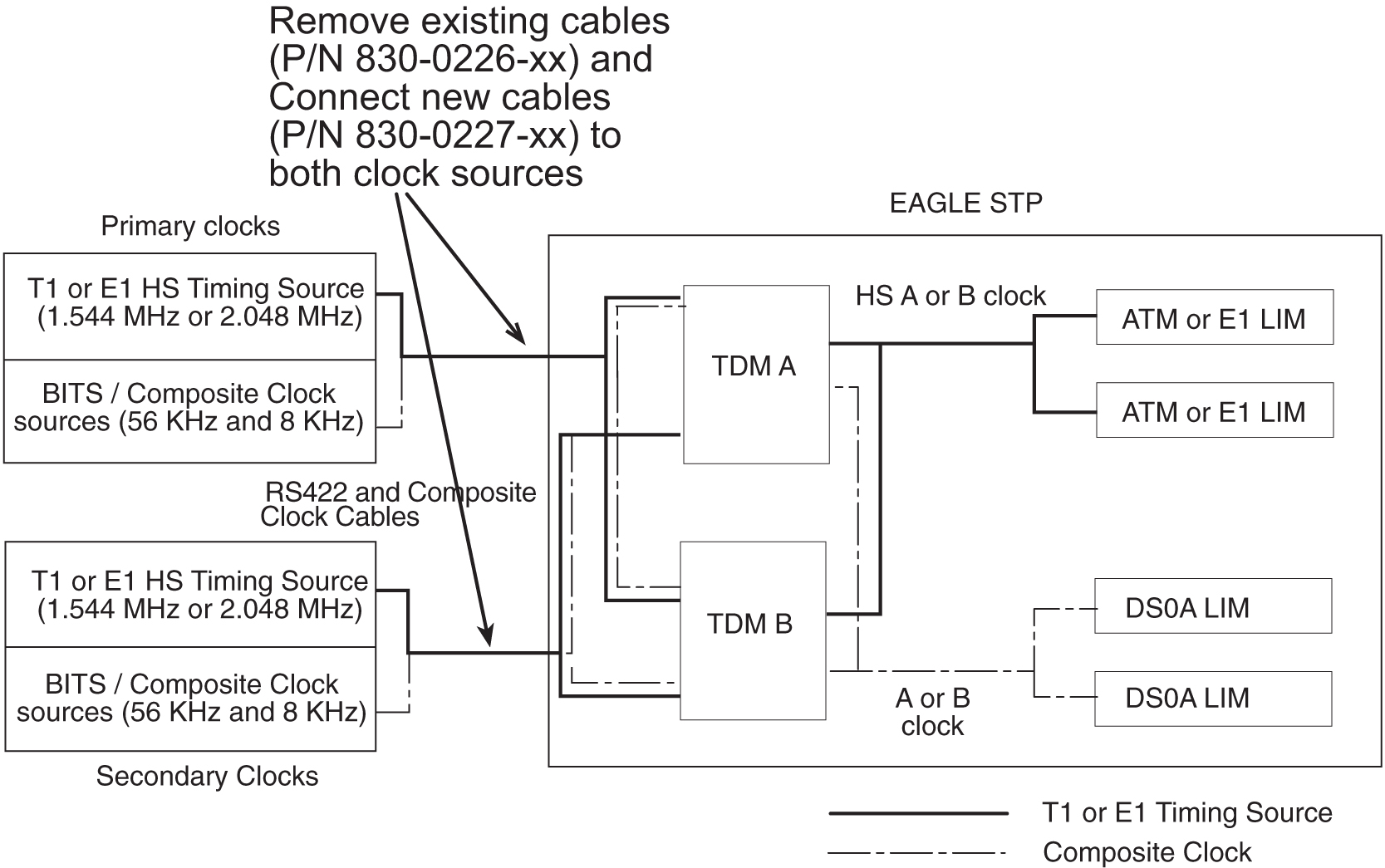
Implementation of the HS Master Timing feature requires the addition of two HS master clock cables on control shelf backplane (P/N 850-0330-03/04). The following figure illustrates the HS master timing concept for control shelves with backplane (P/N 850-0330-03/04).
Only ATM LIM cards or E1 LIM cards can be configured or reconfigured for the HS Master Timing feature. Once the baseline hardware requirements for the HS Master Timing feature have been met:
-
physically install an ATM card, add the card to the system database, and enable it for the HS Master Timing feature (ent-slk:atmtsel=external); or
-
physically install an E1 LIM card, add the card to the system database, and enable it for the HS Master Timing feature (ent-e1:e1tsel=internal).
Reconfigure any existing ATM LIM card or E1 LIM cards to use the HS Master Timing feature. LIM cards that will continue using the composite clock will not require any changes to the card provisioning.
Figure 3-7 HS Master Timing Concept using Control Shelf Backplane (P/N 850-0330-03/04)

Feature Concept
Digital networks require accurate timing sources to maintain the integrity of data transmission. Utilizing high-speed clocking provides improved data synchronization capabilities.
Master Clock
The master clock is the source of timing signals and uses these signals for network synchronization. For the HS Master Timing feature, the site’s master clock can be a T1 (1.544 MHz) or E1 (2.048 MHz) rate clock source on RS422 compatible cable.
System Clocks
The EAGLE STP system clock is derived from the site’s master clock source, which is often the site’s holdover clock. The EAGLE STP typically connects to the site’s composite clocks signals, a primary and secondary clock signal for redundancy. The EAGLE STP’s internal composite clock distributes the signals to all cards at a combined rate of 56 kHz and 8 kHz.
By enabling the HS Master Timing feature on high-speed capable ATM LIM cards or E1 LIM cards, the cards can take their high-speed clock reference directly from the external HS master clock source, such as the master clock source available at the site.
The external HS clock source provides the EAGLE STP with a second system clock. The EAGLE STP can now connect to
-
two 64 kHz composite clocks (primary and secondary clocks) and
-
two T1 (1.544 MHz) or E1 (2.048 MHz) rate clock sources (primary and secondary clocks).
Note:
An STP can be configured for either a T1 (1.544 MHz) or E1 (2.048 MHz) HS master clock source, but not both.
Figure 3-8 System Clocks

TDM Card
EAGLE operation is controlled by Maintenance and Administration Subsystem (MAS) cards. MAS cards consist of two MAS communications application processor (MCAP) cards, two Terminal Disk Module (TDM) cards, and one Maintenance Disk and Alarm (MDAL) card. The TDM card contains the fixed disk drive, the terminal processor for 16 serial I/O ports, and an interface to the MDAL card. The MDAL card contains the removable cartridge drive and alarm logic. Prior to the implementation of the HS Master Timing feature, the TDM card directly supported all of the EAGLE timing functions by distributing composite clock signals to the system.
Internal Clock Defaults
The TDM card generates an internal composite clock when no external composite clock is present on the primary or secondary inputs. If no T1 or E1 high speed clock, is provided, the high-speed system clocks to the LIM cards become inactive.
The TDM card can independently select between primary and secondary high-speed (HS) master clock and primary and secondary composite clock (BITS clock), and switches automatically to the idle clock when one of the active clocks fail.
The following table lists the various clocking modes resulting from the clock inputs received by the TDM card and the resulting clock output to the LIM card.
Table 3-10 Clock Signal Modes
| Site Clock Availability (Input to TDM cards) | Clock Distribution to EAGLE (Possible TDMCard Outputs) | Clock Selection by LIM |
|---|---|---|
|
Primary and/or Secondary HS Master Clock Available |
TDM A and B HS CLK available |
Software selects A or B HS clock |
|
TDM A HS CLK unavailable |
HW selects B HS clock |
|
|
TDM B HS CLK unavailable |
HW selects A HS clock |
|
|
TDM A and B HS CLK unavailable |
No HS clocks available |
|
|
Primary and Secondary HS Master Clock Unavailable |
TDM A and B HS CLK unavailable |
No HS clocks available |
|
Primary and/or Secondary BITS Clock Available |
TDM A and B BITSCLK available |
Software selects A or B composite clock |
|
TDM A BITSCLK unavailable |
HW selects B composite clock |
|
|
TDM B BITSCLK unavailable |
HW selects A composite clock |
|
|
TDM A and B BITSCLK unavailable |
No clocks available (runs on internal) |
|
|
Primary and Secondary BITS Clock Unavailable |
TDM A and B BITSCLK unavailable |
No clocks available (runs on internal) |
|
Note: “Unavailable” means the clock is not valid or not present. |
||
For a timing source, ATM LIM cards or E1 LIM cards use the system clock required by their card type and the Generic Program Load (GPL) installed on the card. For detailed information on configuring ATM or E1 cards, refer to Database Administration Manual - SS7 of your current documentation suite.
MCAP Card
To support the HS Master Timing feature, a new Programmable Read-Only Memory (PROM) is required for the MCAP card (containing a new Clock LCA bit file in the IMT quadrant of the PROM), new interprocessor message transport (IMT) GPL for LIM cards (SS7ANSI, CCS7ITU, SS7GX25, STPLAN, GLS, SCCP), BPHCAP GPL for High Capacity Application Processor (HCAP) (ATMANSI) cards, BPDCM GPL for DCM cards, and a new OAM GPL.
Administration
The HS Master Timing feature allows a high-speed capable (T1 or E1 rate) Link Interface Module (LIM) installed in an EAGLE STP to receive its transit timing reference directly from an external high-speed master clock source, instead of slaving to the timing information contained in the received data. The high-speed master timing feature is enabled through the provisioning of at least one high speed link (ATM or E1 LIM card). At that time, the GPL required for the feature is downloaded from the MCAP card to the TDM card. For provisioning high speed links, the following commands have been changed to support master timing:
-
REPT-STAT-CARD:MODE=FULL -
REPT-STAT-CLK -
ENT-SLK -
RTRV-SLK -
ENT-E1 -
CHG-E1
Refer to Commands Manual for current usage information.
3.78 High-Speed Multiplexer (HMUX) (Release 27.2)
The High-Speed Multiplexer (HMUX) supports the EAGLE Large System feature, which expands the number of links supported by the EAGLE STP. The HMUX enhances the IMT bus by introducing a new 1Gb/sec inter-shelf bus bandwidth. The intra-shelf bus data rate will remain the same at 125Mb/sec.
The HMUX feature also enhances IMT performance by transmitting data between shelves only when it is necessary. Traffic between EAGLE cards on the same shelf will be allowed to remain on the shelf IMT, and will not be required to transmit between shelves. Traffic between shelves will not be required to pass onto an intra-shelf IMT bus if it is not necessary.
Introduction of the HMUX transforms each EAGLE IMT bus from a single ring topology running at 125Mbps, to a central primary ring operating at 1Gb/sec, with a maximum of sixteen secondary rings running at 125Mbps. Refer to Figure 3-9.
Figure 3-9 HMUX Ring Topology
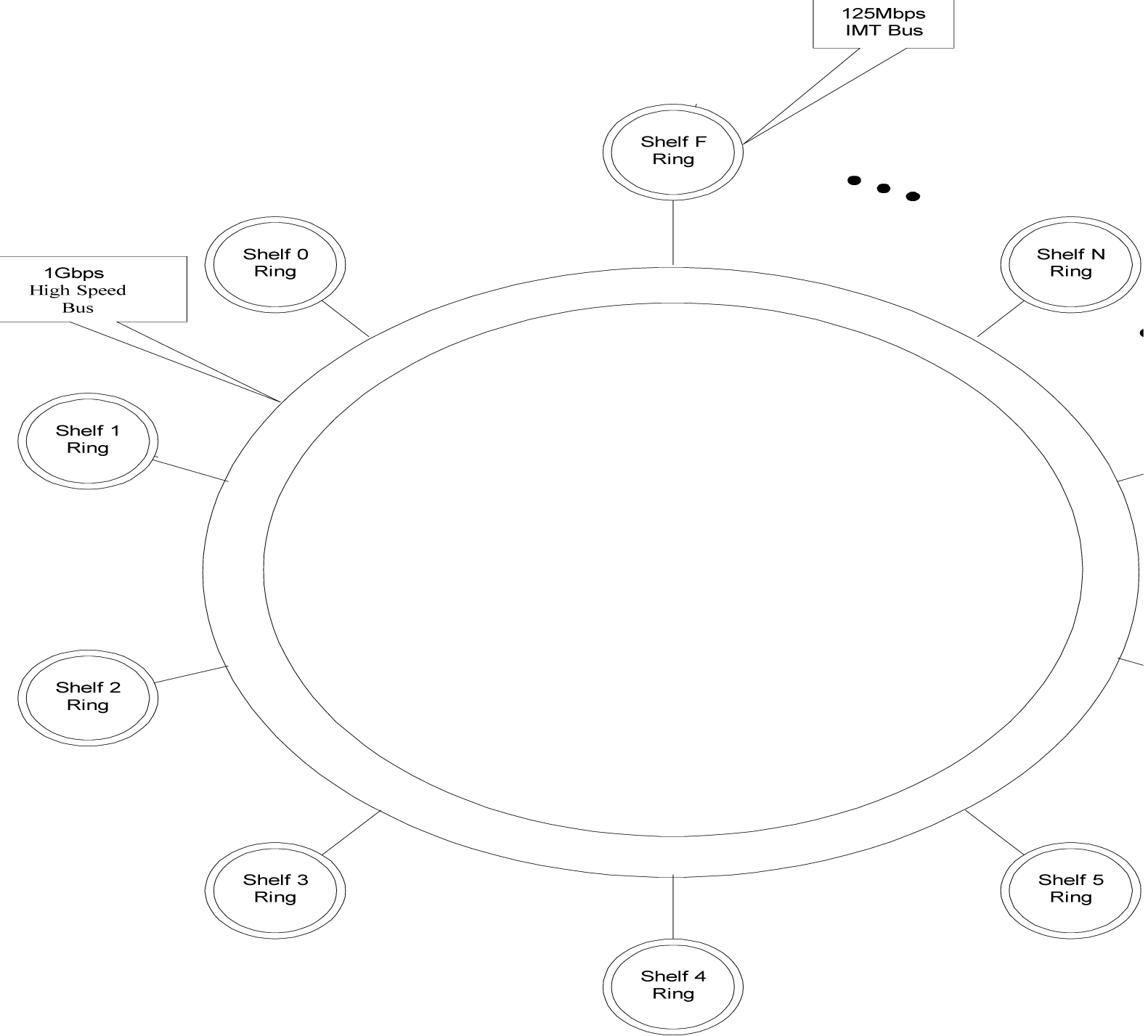
Hardware Requirements
Support of this feature requires the following hardware:
Table 3-11 Hardware Required for High-Speed Multiplexer
|
Hardware |
Assembly Part Number |
|
HMUX |
870-1965-01 or later |
|
TDM |
870-0774-10 or later |
|
Control Shelf and |
870-2321-01 or later |
|
Adapter cable |
830-0857-01 |
|
MCAP-256 w/ special PROM with FPGA logic files for new ECAM CLOCK LCA |
870-1307-07 |
Upgrade Considerations
The following EAGLE tables will be modified/converted/created as part of the upgrade for this feature:
-
STPOPTS.TBL/BKP
-
(T)BPHMUX.ELF
3.79 Holdover BITS Clock Support (Release 21.0)
The holdover BITS clock is an optional external device that provides clock input to the EAGLE for a specified period of time when the BITS clock fails. The holdover BITS clock resides in the OAP frame of the EAGLE. This feature adds additional outputs on the control shelf to control the holdover BITS clock. The holdover BITS clock is a Telecom Solutions Digital Clock Distributor, DCD-523. The holdover BITS clock maintains clock synchronization for 15 seconds. This meets the Bellcore requirement as specified in TR-NWT-001244. When used with the EAGLE, the holdover BITS clock contains the following cards:
-
2 CI cards - clock inputs A and B
-
2 ST3E cards - clocks A and B
-
2 TOCA cards in card locations TO1 and TO2 - outputs to the EAGLE
The outputs of the TOCA cards are connected to a wire wrap panel mounted on top of the holdover BITS clock. The clock inputs on the EAGLE control shelf are connected to the wire wrap panel.
3.80 HomeSMSC Match with Digits Option for Portability Check for Mobile Originated SMS (Release 39.0)
The HomeSMSC Match with Digits Option for Portability Check for Mobile Originated SMS (HomeSMSC Match) enhances the ability of the EAGLE 5 ISS to compare the Home Short Message Service Center (HomeSMSC) digits in the SCCP CdPA of incoming GSM MAP Mobile Originated Forward Short Messages (MO_FSM) to HomeSMSCs that are stored in the database. If the beginning digits of the incoming HomeSMSC matches a stored HomeSMSC, then the HomeSMSCs are considered a match, even if additional digits are attached to the end of the incoming HomeSMSC. If a match is found, then the message is rejected.
3.81 Hybrid INP/IDP Relay Service (Release 43.0)
The Hybrid INP/IDP Relay Service feature allows the existing Prepaid IDP Query Relay feature (Part Number 893-0160-01) to send CONNECT, CONTINUE, or RELEASECALL responses based on the RTDB lookup results. This functionality includes the ability to configure whether the CutAndPaste parameter is included in the CONNECT message when the message is sent from the Prepaid IDP Query Relay feature.
The functionality is configured for the Prepaid IDP Query Relay feature using a new INPRTG Service Action, which is applicable to the IDPRCDPN(X) and IDPRCGPN NPP services. Refer to the Numbering Plan Processor (NPP) Overview for more information.
The Hybrid INP/IDP Relay Service feature also allows a Service Control Point (SCP) Global Title Address (GTA) to be provisioned based on a Service Key. This functionality is configured using a new SKGTARTG Service Action which is applicable to IDPRCDPN(x) services. This Service Action allows the IDP message to be routed to the provisioned SCP GTA. If the functionality is not configured, then the message is routed to the incoming SCCP Called Party Address (CdPA) GTA.
Note:
If both A-Party Routing and Service Key based GTA routing are configured, then the Service Key based GTA routing takes precedence.3.82 IAR NP Service Portability (Release 41.1)
Service Portability support for the IAR Number Portability (IAR NP) feature allows the CDPNNP Service Action to use RTDB GRN Entity digits for own-network GSM or IS41 subscribers to populate the Numbering Plan Processor (NPP) RN Formatting Action value.
Service Portability functions are applied by the CDPNNP Service Action. The RN Formatting Action value is populated only when NPTYPE Evaluation success criteria are met when Service Portability processing is applied.
3.83 Idle Terminal Port Logout (Release 21.0)
The EAGLE keeps track of how long a login session has remained idle. Every minute, the EAGLE examines all of the login sessions currently active. Whenever a login session has been idle (idle is defined as no input from the user) for more than the maximum allowable time (provisionable on a per-port basis), the session is ended by forcing an automatic logout.
The EAGLE issues a message to the scroll area of all system administrator terminals whenever a logout occurs. A slightly different message is issued when an idle time logout occurs:
User xxxxxxxx auto logged out (idle time exceeded) on port yy.
where xxxxxxxx is the user ID that was logged off and yy is the port that the user ID was using before the logoff. In addition to being issued to all system administrator terminals, this same message is sent to the scroll area of the idle terminal that is being logged out.
The idle time logout is designed so that it will not interfere with existing or planned EAGLE features that might falsely or undersirably trigger the idle time logout:
-
The idle time logout feature is suspended for a port while that port is in the process of transferring a file.
-
SEAS ports are not affected by idle port logout. SEAS ports are unique in that no login is required in order to access the EAGLE with a SEAS port, and thus there is no login session whose idle time can be monitored.
The maximum idle time value can be configured on a per-port basis; different maximum idle times can be established for each port, using the tmout parameter of the chg-trm command.
The system administrator is allowed to set a port's idle timeout value to 0. This indicates that a user ID may remain idle on the port indefinitely without being automatically logged off due to idle time expiration.
The system default value for the tmout parameter is 30 minutes.
The monitoring of a terminal’s idle time (tmout) and the automatic logout function only applies to terminal types VT320 (type=vt320), KSR, (type=ksr), and SCCS (type=sccs). The tmout parameter can be specified with other terminal types, but it will have no effect.
During a Kermit file transfer, the idle time monitoring is temporarily suspended and the port’s idle time is reset to 0 and does not resume until after the file transfer completes, even though there is no user input from the terminal during the file transfer operation. This prevents a terminal from being automatically logged off immediately after a file transfer completes. For example, if the value of the tmout parameter for a terminal is 1 minute and a file transfer is performed that takes 5 minutes. The terminal idle monitor is suspended during the file transfer and does not resume until the file transfer operation completes. Therefore, the terminal is logged off 1 minute after the file transfer completes unless there is additional user input.
The idle port logout occurs even if a port is in the process of executing a command when the idle threshold is exceeded. For example, if the chg-pid command is executed and the user never supplies any input to the Enter Old Password : prompt, when the terminal’s idle time threshold is exceeded, the terminal is logged off and the command that was in progress is aborted.
3.84 IDP A-Party Blacklist (Release 41.1)
The IDP A-Party Blacklist feature enhances the Prepaid IDP Query Relay feature to provide a generic framework to support subscriber blacklisting capability that works with either a query-based or relay-based method. The feature supports the blacklist check on the Calling Party (A-Party or CgPN) number in the IDP CAMEL or INAP message.
The EAGLE receives an IDP query message destined to the EAGLE Point Code or a prepaid IDP message sent to the EAGLE Point Code for translation to prepaid SCP. MSCs are configured with a trigger point to send an IDP message for just post-paid or prepaid subscribers or for all subscribers in the network, depending on the use case for a particular operator.
The EAGLE receives the IDP message and performs the necessary discrimination and pre-processing using the current prepaid IDP Relay functions (SCCP CdPA check, CgPA check and Common Screening List SK BCSM filter). The EAGLE decodes the Calling Party Number (from the CgPN parameter) from the message. If the subscriber number is blacklisted, the number is entered with a blacklist flag and optional routing number information. If a match is found, EAGLE returns a Connect message with Routing Number (if provisioned). This Routing Number could be a service center number that receives the re-routed call and provides the necessary assistance. If the subscriber is not blacklisted, the IDP message continues normal processing (if it is prepaid IDP message), or a CONTINUE response is generated (if the blacklist query is received).
3.84.1 Feature Control Requirements
- FAK for Part Number 893-0332-01
- The IDP Relay feature (Part Number 893-0160-01) must be turned on before the IDP A-Party Blacklist feature can be enabled.
- The IDP A-Party Blacklist feature cannot be enabled if the Service Portability feature (Part Number 893-0343-01) is enabled.
- A temporary FAK cannot be used to enable the feature.
- The feature cannot be turned off after it is turned on.
3.85 IDP A-Party Blacklist (EPAP 13.0)
The IDP A-Party Blacklist feature for EAGLE 5 ISS enhances the Prepaid IDP Query Relay feature to provide a generic framework to support the subscriber blacklisting capability that works with either a query-based or relay-based method. The feature supports the blacklist check on the Calling Party (A-Party or CgPN) number in the Initial Detection Point (IDP) Customized Applications for Mobile Networks Enhanced Logic (CAMEL) or Intelligent Network Application Protocol (INAP) message.
For EPAP, this feature allows calling and called-party blacklist data to be associated with Directory Numbers (DNs) and DN Blocks that reside in the PDBA and RTDB databases. The blacklist data will be used by the EAGLE to support IDP Queries. If the calling party is associated with a blacklisted flag and a Generic Routing Number (GRN), then a connect message is sent back to the switch along with the GRN. The GRN is then used to re-route the call to a predetermined destination. Currently only Calling party is used by the EAGLE 5 ISS.
Hardware Requirements
Service Module cards (DSM cards with at least 4G of memory, E5-SM4G cards, or a mixture of both).
Limitations
The IDPR Relay feature must be enabled and turned on before any of the new IDP enhancements can be enabled.
- Prepaid subscribers can have either prepaid types or associated portability status, but not both.
- The customer cannot have different SCP servers for SMS and IDPR handling for the same subscriber.
- Care must be taken when performing subscriber provisioning to make sure that the PT type does not conflict with any other EAGLE 5 ISS feature solutions.
- To select an IDPRCDPN NPP service rule set, the CdPN number of digits in the received IDP/IDPSMS message must be non-zero.
- Network conversion between the incoming msu-type and a connect/continue response is not supported.
- Blacklist feature changes will support a Connect/Continue response only for InitialDP messages (Opcode 0). IDPSMS/IDPGPRS messages will not be checked by the Blacklist feature, but this does not affect processing by any other IDPR feature components.
- Network conversion between the msu-type of the incoming IDP/IDPSMS message and the associated prepaid PPSOPTS:PC msu-type is only supported between ITU-I/ITU-N network types.
- If both IDPS and IDP SK Routing feature functionality is required on a NODE for the same Service Key and EventType BCSM parameters, then the srvsel should be different for both. IDPS encodes a “continue” when a match is made in the skbcsm list for SK-BCSM parameters of incoming messages, but IDPR SK Routing will attempt to route the message to the defined prepaid server.
PDBI Changes
- Calling Party Blacklist (
cgbl) - Called Party Blacklist (
cdbl)
These parameters can have the values "no" (default) or "yes".
The updated commands are:
- ent_sub
- rtrv_sub
- upd_sub
Example: If the Calling Party Blacklist is selected as ‘no’ and the Called Party Blacklist is selected as ‘yes’, PDBI command will be as follows:
ent_sub(iid 3, bdn 123456, edn 654321, pt 12, cdbl yes, asd 545454, rn 234567)
Feature Control Requirements
See the EAGLE 5 ISS Release 41.1 Feature Notice.
3.86 IDP A-Party Routing (Release 41.1)
The IDP A-Party Routing feature allows routing for IDP or IDPSMS messages to be performed using the A-Party Calling Party Number (CgPN). This feature provides a routing alternative to the existing SCCP GTA routing. A-Party routing is performed using a new CGPN Service Action and invoking new algorithms during post-NPP processing.
If successful IDP A-Party routing occurs, then an IDP or IDPSMS message is routed to an available Prepaid Server from a list of provisioned servers in the MRNSET or MAPSET load share table. If routing failure occurs, then a UDTS is sent to the originator or the message is discarded.
If all of the required data for IDP A-Party routing is not provisioned, then routing falls through to GTT routing.
Interaction with IDP Service Key Routing feature
If the IDP Service Key Routing (IDP SK Routing) or IDP A-Party Routing feature is turned on, then the system behaves as if the routing provided by that feature was the only routing option.
If both features are turned on, and the A-Party Routing Service Action is provisioned, then both features are considered for processing. The IDP A-Party Routing option is checked first. If IDP A-Party Routing is not attempted, and the IDP SK Routing option is provisioned, then IDP SK Routing is considered.
If IDP A-Party Routing is not attempted, and the IDP SK Routing option is not provisioned, then GTT routing is performed.
Whether A-Party Routing or SK Routing is attempted, once a message attempts to route, the message does not attempt any other routing method, including SCCP GTA/GTT routing. If routing fails, then the attempt is considered an IDPR routing failure, a UDTS is sent, and the message is discarded.
Note:
Post-processing network conversion for IDP A-Party Routing and IDP SK Routing can only be performed for ITU-I or ITU-N network types.3.86.1 Feature Control Requirements
- FAK for Part Number 893-0333-01
- The IDP Relay feature (Part Number 893-0160-01) must be turned on before the IDP A-Party Routing feature can be enabled.
- A temporary FAK cannot be used to enable the feature.
- The feature cannot be turned on and off.
Note:
The IDP A-Party Routing and the IDP SK Routing features are not dependent or exclusive with each other. The features can be enabled, turned on, and used independently or together.3.87 IDP Relay Support for CAP v3 IDP-SMS (Release 40.0)
The IDP Relay Support for CAP v3 IDP-SMS feature allows the Prepaid IDP Query Relay (IDP Relay) feature to support CAP v3 IDPSMS messages. The Called Party Number (CdPN) is derived from the Destination Subscriber Number in the message, and an EventTypeSMS field is used instead of BCSM.
For SKBCSM lookup in the CSL table, a hexadecimal value of 0x50 is added to the EventTypeSMS from the MSU before finding a match. SKBCSM lookup is considered successful when the BCSM value provisioned in the CSL table has a value that is equal to 0x50 + incoming EventTypeSMS .
3.88 IDP Screening for PrePaid (Release 34.3)
Description
The IDP Screening for Prepaid feature screens GT-routed messages resulting from voice and text calls from a prepaid subscriber to determine whether the subscriber has a “24/7 Call and Text Unlimited” or a “24/7 Text Unlimited” calling plan and then routes the call accordingly.
For a voice or text (short message) call originated by a prepaid subscriber, the serving MSC formulates an INAP IDP message which is destined for a prepaid engine that checks the subscriber's credit status. The IDP Screening for PrePaid feature causes EAGLE 5 SAS to intercept the IDP message and determine whether the subscriber has one of the calling plans referenced above.
Voice and text calls are identified by a predefined Service Key. The value assigned to the Service Key is set by an originating MSC when the call reaches an Intelligent Network (IN) trigger. These values indicate whether the subscriber has the "24/7 Call and Text Unlimited" or "24/7 Text Unlimited" calling plan.
If the subscriber has one of the calling plans, the EAGLE 5 SAS determines whether the call is an in-network call (a call from one subscriber to another belonging to the same network). For an in-network call, the EAGLE 5 SAS returns an INAP Continue message to instruct the MSC to bypass the credit check and continue the call. If the call is not an in-network call, EAGLE 5 SAS routes the calls to the prepaid engine to have the credit check performed.
If the call originates from a non "24/7 Call and Text Unlimited" or non "24/7 Text Unlimited" prepaid subscriber, the EAGLE 5 SAS routes the IDP message to its intended destination.
This feature requires a feature access key.
Hardware Requirements
-
After the IDP Screening for Prepaid feature is turned on, no TSM SCCP cards can be provisioned.
-
Only DSM cards are used with the IDP Screening for Prepaid feature.
3.89 IDP Service Key Routing (Release 41.1)
The IDP Service Key Routing (IDP SK Routing) feature allows routing to occur based on the Service Key and EventType BCSM parameters in the incoming IDP or IPDSMS message. IDP SK routing can occur independently or can be used as a fall-through option for the IDP A-Party Routing feature. See IDP A-Party Routing (Release 41.1) for a description of the interaction between the features.
If successful IDP SK routing occurs, then an IDP or IDPSMS message is routed to an available Prepaid Server from a list of provisioned servers in the MRNSET or MAPSET load share table. If routing failure occurs, then a UDTS is sent to the originator or the message is discarded.
If all of the required data for IDP SK routing is not provisioned, then routing falls through to GTT routing.
3.89.1 Feature Control Requirements
- FAK for Part Number 893-0336-01
- The IDP Relay feature (Part Number 893-0160-01) must be turned on before the IDP SK Routing feature can be enabled.
- The feature cannot be enabled with a temporary FAK.
- The feature cannot be turned off after it has been turned on.
Note:
The IDP A-Party Routing and the IDP SK Routing features are not dependent or exclusive with each other. The features can be enabled, turned on, and used independently or together.3.90 IDPR Intl Normalization (Release 37.10)
The IDPR Intl Normalization feature allows the IDP Relay feature to process INAP/CAP messages containing routing numbers (RNs) that have leading zeros and a National Escape Code (NEC), which usually has a value of 0.
If the message has an associated NEC, then the message is received by the EAGLE 5 ISS with the message number in the format <NEC><DN>. If the IDPR feature is turned on, then the RN is inserted after the NEC, resulting in a format of <NEC><RN><DN>.
If both the NEC and RN have a value of 0, then the signaling control point (SCP) interprets the two zeros as an International Escape Code (IEC), which is usually 00, instead of NEC+RN.
The IDPR Intl Normalization feature adds 00 and the Country Code (CC) before the RN in the message and reconstructs the Called Party Number (CdPN) in the outgoing INAP/CAP message as <00><CC><RN><DN>.
3.90.1 Feature Control Requirements
The IDPR Intl Normalization feature has the following feature control requirements:
- A FAK for part number 893-0226-01
- The Prepaid IDP Query Relay feature must be enabled and turned on before the IDPR Intl Normalization feature can be enabled.
- A temporary FAK cannot be used to enable the feature.
- The feature can be turned on and off.
3.90.3 Limitations
When this feature is implemented, the capacity limits for combinations of DN/IMSI will be less than what is supported today.
- Existing limit: {DN, IMSI} = {36M, 60M}, {12M, 82M} and {6M, 90M}
- New limit for EPAP 10.0: {DN, IMSI} = {36M, 52M}, {12M, 75M} and {6M, 82M}
This decrease in capacity is based on high-level engineering design for the feature. Since these combinations are not used in the field, this limitation does not affect any customers.
3.91 IDPR TON Mapping for CdPN BCD Format (Release 44.0)
The IDPR TON mapping feature allows configuration of the mapping that occurs when encoding or decoding the BCD parameter for a Called Party or Calling Party number. The Type of Number (TON) value, Nature of Address Indicator (NAI) value, and the type of mapping used (NAI to TON for encoding or TON to NAI for decoding) can be configured.
3.92 IETF M3UA for “A” Link Connectivity (Release 28.1)
Description
To connect to a variety of IP enabled SCP's, the VXi Softswitch, or other IP enabled network elements, the EAGLE STP and IP7 Secure Gateway must use industry standard protocols. In the IETF Signaling Transport (SIGTRAN) model, SS7 MTP3-User Adaptation Layer (M3UA) is a User Adapter layer which resides on top of SCTP, necessary for connection to IP enabled network elements.
Hardware Requirements
This feature requires a SSEDCM (Single Slot Enhanced DCM).
3.93 IETF M3UA Support including IETF SUA (IP7 Release 5.0)
Description
Although widely accepted throughout the industry, the TALI protocol is not a standard adapter layer protocol at this time. To interoperate with various vendors, the adapter layer protocols produced by the IETF must be implemented on the Secure Gateway. The concepts defined in the IETF drafts will provide a building block for better support of fail-over scenarios that can be implemented in TALI.
The M3UA Layer is designed to fit the need for signaling protocol delivery from an SS7 Signaling Gateway (SG) to a Media Gateway Controller (MGC) or IP-resident Database. The layer is expected to meet the following criteria:
-
Support for the transfer of all SS7 MTP3-User Part messages (for example, ISUP, SCCP, TUP, and so forth)
-
Support for the seamless operation of MTP3-User protocol peers
-
Support for the management of SCTP transport associations and traffic between a SG and one or more MGCs or IP-resident Databases
-
Support for MGC or IP-resident Database process fail-over and load-sharing
-
Support for the asynchronous reporting of status changes to management.
The SUA Layer is designed to fit the need for the delivery of SCCP-user messages (MAP and CAP over TCAP, RANAP, and so forth) and new third generation network protocol messages over IP between two signaling endpoints. Consideration is given for the transport from an SS7 Signaling Gateway (SG) to an IP signaling node (such as an IP-resident Database). This protocol can also support transport of SCCP-user messages between two endpoints wholly contained within an IP network.
Refer to the Database Administration Manual Features for current information on this feature.
New Hardware
Same as IETF SCTP.
Upgrade Considerations
Same as IETF SCTP.
Limitations
Same as IETF SCTP.
3.94 IETF Protocol Update (Release 28.1) (IP7 Release 6.0)
Description
Since the introduction of the IETF Sigtran protocols in IP7 Secure Gateway Release 5.0, the IETF has created newer versions of these protocols. This feature updates the IP7 Secure Gateway and EAGLE IPLIMx implementation of these protocols to the current revisions.
Note:
This is a non-orderable feature required for the three IETF Connectivity features and the IPLIM Protocol Support Enhancement feature.
Hardware Requirements
This feature requires a SSEDCM (Single Slot Enhanced DCM).
3.95 IETF SCTP for “A” Link Connectivity (Release 28.1)
Description
To connect to a variety of IP enabled SCP's, the VXi Softswitch, or other IP enabled network elements, the EAGLE STP and IP7 Secure Gateway must use industry standard protocols. In the IETF Signaling Transport (SIGTRAN) model, SCTP is the transport layer for all the User Adapter layers.
SCTP is a reliable transport protocol operating on top of a connectionless packet network such as IP. It offers the following services to its users:
-
acknowledged error-free non-duplicated transfer of user data,
-
data fragmentation to conform to discovered path MTU size,
-
sequenced delivery of user messages within multiple streams, with an option for unorder delivery of individual user messages,
-
optional bundling of multiple user messages into a single SCTP packet, and
-
network-level fault tolerance through supporting of multi-homing at either or both ends of an association.
The development of SCTP was necessitated by limitations within TCP. TCP has performed immense service as the primary means of reliable data transfer in IP networks. However, an increasing number of recent applications have found TCP too limiting, and have incorporated their own reliable data transfer protocol on top of UDP. The limitations which users have wished to bypass include the following:
-
TCP provides both reliable data transfer and strict order-of-transmission delivery of data. Some applications need reliable transfer without sequence maintenance, while others would be satisfied with partial ordering of the data. In both of these cases the head-of-line blocking offered by TCP causes unnecessary delay.
-
The stream-oriented nature of TCP is often an inconvenience. Applications must add their own record marking to delineate their messages, and must make explicit use of the push facility to ensure that a complete message is transferred in a reasonable time.
-
The limited scope of TCP sockets complicates the task of providing highly available data transfer capability using multi-homed hosts.
-
TCP is relatively vulnerable to denial of service attacks, such as SYN attacks.
The transport of PSTN signaling across the IP network is an application for which all of these limitations of TCP are relevant.
This feature is available on the IPGWx GPL and IPLIMx GPL in both the EAGLE STP and IP7 Secure Gateway products in Release 28.1 of the EAGLE STP, and IP7 Secure Gateway Release 5.0.
SCTP is a protocol designed to operate on top of a non-reliable protocol such as IP, but yet provide a reliable data delivery to the SCTP user.
Hardware Requirements
This feature requires a SSEDCM (Single Slot Enhanced DCM).
3.96 IETF SCTP Support (IP7 Release 5.0)
Description
SCTP is a reliable transport protocol operating on top of a connectionless packet network such as IP. It offers the following services to its users:
-
Acknowledged error-free non-duplicated transfer of user data
-
Data fragmentation to conform to discovered path MTU size
-
Sequenced delivery of user messages within multiple streams, with an option for out-of-order-of-arrival delivery of individual user messages
-
Optional bundling of multiple user messages into a single SCTP packet
-
Network-level fault tolerance through supporting of multi-homing at either or both ends of an association
The development of SCTP was necessitated by limitations within TCP. TCP has performed immense service as the primary means of reliable data transfer in IP networks. However, an increasing number of recent applications have found TCP too limiting, and have incorporated their own reliable data transfer protocol on top of UDP. The limitations which users have wished to bypass include the following:
TCP provides both reliable data transfer and strict order-of-transmission delivery of data. Some applications need reliable transfer without sequence maintenance, while others would be satisfied with partial ordering of the data. In both of these cases the head-of-line blocking offered by TCP causes unnecessary delay.
The stream-oriented nature of TCP is often an inconvenience. Applications must add their own record marking to delineate their messages, and must make explicit use of the push facility to ensure that a complete message is transferred in a reasonable time.
The limited scope of TCP sockets complicates the task of providing highly available data transfer capability using multi-homed hosts.
TCP is relatively vulnerable to denial of service attacks, such as SYN attacks.
The transport of PSTN signaling across the IP network is an application for which all of these limitations of TCP are relevant.
Refer to the Database Administration Manual - Features for the current implementation of this feature.
New Hardware
Hardware support is required for implementation of the IETF Adapter Layer Support feature. Starting with this feature, the new EDCM card is introduced. Refer to the NSD Hardware Manual for current information on this card.
These differences in memory are the main reasons for hardware support. We are required to make both socket/association provisioning and card loading decisions differently based on the card type.
Upgrade Considerations
This feature has a unique upgrade consideration than other features in that the specification for which the feature is being developed is not "frozen" until after the feature is complete. This raises the issue of incompatibility between the final specification and this feature. Since the specification is the initial version for the adapter layer, the protocol has defined the version number to be fixed to 1. Therefore, it is not possible to modify the version number from this feature perspective. Another issue is that the impact of any specification changes after this feature is completed is not necessarily impacting the compatibility of the protocol. It is expected that the approved version of revision 1 of the adapter layers is supported at some period in time and that by upgrading the software solves compatibility issues. Another solution is to use a new adapter layer index for the pre-official version of the protocol and convert and fielded releases to the new adapter layer index. The ASPLOG PASS command shows the version of the UA adapter supported. The problem with supporting a revision of a draft is a later revision may be incompatible. The drafts make no provision for support between revisions so a revision 3 of version 1 SUA can't be differentiated between revision 6 of version 1 SUA.
Limitations
The memory requirements for an association are greater than for a socket. Because of this, more associations may be provisioned on the EDCM card.
Not only are socket/association limits based on memory, so is the ratio of associations to sockets. This ratio known as the "trade ratio" defines the number of sockets, which are equivalent to one association with respect to memory consumption.
3.97 IETF SUA for “A” Link Connectivity (Release 28.1)
To connect to a variety of IP enabled SCP's, the VXi Softswitch, or other IP enabled network elements, the EAGLE STP and IP7 Secure Gateway must use industry standard protocols. This feature implements the SCCP User Adaptation Layer (SUA). SUA is an adaptation layer protocol, similar to TALI, which transports SCCP User level protocols.
The SUA Layer was designed to fit the need for the delivery of SCCP-user messages (MAP & CAP over TCAP, RANAP, etc.) and new third generation network protocol messages over IP between two signaling endpoints. Consideration is given for the transport from an SS7 Signaling Gateway (SG) to an IP signaling node (such as an IP-resident Database). This protocol can also support transport of SCCP-user messages between two endpoints wholly contained within an IP network. The layer is expected to meet the following criteria:
-
Support for transfer of SS7 SCCP-User Part messages (e.g., TCAP, RANAP, etc.).
-
Support for SCCP connectionless service.
-
Support for SCCP connection oriented service.
-
Support for the seamless operation of SCCP-User protocol peers
-
Support for the management of SCTP transport associations between a SG and one or more IP-based signaling nodes).
-
Support for distributed IP-based signaling nodes.
-
Support for the asynchronous reporting of status changes to management.
Hardware Requirements
This feature requires a SSEDCM (Single Slot Enhanced DCM).
3.98 IETF SUA Support (Release 34.0)
Description
- Replaces Draft Version 3 support on the IPGWx GPL with SUA RFC.
- Provides support for SCCP Connectionless messages via SUA CLDT and CLDR. Connection oriented messages are not supported.
- Provides support for SUA Signaling Network Management Messages.
Hardware Requirements
An EDCM (single-slot) P/N 870-2372-01 Rev E is required for SUA RFC.
Refer to the hardware baseline of this release.
Limitations
- The version of SUA implemented in this release is NOT backward compatible with the SUA version currently available on EAGLE 5 SAS releases.
- Only the Connections Message transfer part of the SUA protocol is supported for class 0 and class 1 SCCP messages.
- To remove a routing context from a routing key, the routing key must be deleted and re-entered.
3.99 Implementation of SNMP Agent (IP7 Release 2.0)
Overview
This feature implements a Simple Network Management Protocol (SNMP) agent on each DCM that runs an ss7ipgw or iplim general program load (GPL). SNMP is an industry-wide standard protocol used for network management. SNMP agents interact with network management applications called Network Management Systems (NMSs).
Supported Managed Object Groups
The SNMP agent maintains data variables that represent aspects of the DCM card. These variables are called managed objects and are stored in a management information base (MIB). The SNMP protocol arranges managed objects into groups. The following table shows the groups that IP7 release 2.0 supports.
Table 3-12 SNMP Object Groups Supported by IP7 Release 2.0
| Group Name | Description | Contents |
|---|---|---|
|
system |
Text description of agent in printable ASCII characters |
System description, object identifier, length of time since reinitialization of agent, other administrative details |
|
interfaces |
Information about hardware interfaces on the DCM |
Table that contains for each interface, speed, physical address, current operational status, and packet statistics |
|
ip |
Information about host and router use of the IP |
Scalar objects that provide IP-related datagram statistics, and 3 tables: address table, IP-to-physical address translation table, and IP-forwarding table |
|
icmp |
Intranetwork control messages, representing various ICMP operations within the DCM |
26 scalar objects that maintain statistics for various Internet Control Message Protocol (ICMP) messages |
|
tcp |
Information about TCP operation and connections |
14 scalar objects that record TCP parameters and statistics, such as the number of TCP connections supported and the total number of TCP segments transmitted, and a table that contains information about individual TCP connections |
|
udp |
Information about UDP operation |
4 scalar objects that maintain UDP-related datagram statistics, and a table that contains address and port information |
|
snmp |
Details about SNMP objects |
30 scalar objects, including SNMP message statistics, number of MIB objects retrieved, and number of SuNMP traps sent |
Supported SNMP Messages
The SNMP agent interacts with up to two NMSs by:
-
Responding to Get and GetNext commands sent from an NMS for monitoring the DCM.
-
Responding to Set commands sent from an NMS for maintaining the DCM and changing managed objects as specified.
-
Sending Trap messages to asynchronously notify an NMS of conditions such as a link going up or down. Traps provide a way to alert the NMS in a more timely fashion than waiting to for a Get or GetNext from the NMS. In this release, only the following traps are supported:
-
linkUp, sent when one of the ports on the DCM initially comes up or recovers from a previous failure
-
linkDown, sent when one of the ports on the DCM fails
-
Deviations from SNMP Protocol
The following table shows how IP7 release 2.0 deviates from the standard SNMP protocol definition.Table 3-13 Deviations from SNMP Protocols
| Group | Variable Name | Usage | Deviation |
|---|---|---|---|
|
system |
sysContact |
Text identification of contact information for agent |
Cannot be set by Set command; may be set only by |
|
sysLocation |
Physical location of agent |
Cannot be set by Set command; internally set using configuration data already available; set to <CLLI>-<slot of DCM> |
|
|
sysName |
Administratively assigned name for agent |
Cannot be set by Set command; internally set using configuration data already available; set to <CLLI>-<slot of DCM> |
|
|
interface |
ifAdminStatus |
Desired state of the interface |
Cannot be set by Set command (to ensure that an NMS does not disrupt SS7 traffic by placing an IP interface in a nonoperable state) |
|
ip |
ipForwarding ipDefaultTTL ipRoute Dest ipRouteIfIndex ipRouteMetric1-5 ipRouteNextHop ipRouteType iprouteAge ipRouteMask |
IP route-specific values |
Cannot be set by Set command |
|
ipNetToMediaIfIndex ipNetToMediaPhysAdress ipNetToMediaNetAddress ipNetToMediaType |
IP-address specific information |
Can be set by Set command, but not saved across DCM reloads |
|
|
tcp |
tcpConnState |
State of a TCP connection |
Cannot be set by Set command |
|
snmp |
snmpEnableAuthenTraps |
Indicate whether agent is permitted to generate authentication failure traps |
Cannot be set by Set command |
3.100 Improved Routing Management (Release 20.0)
This feature allows the EAGLE to use E-links, allows the user to make link type assignment for display purposes, and provides two new procedures for handling transfer-prohibited (TFP) network management messages.
Before beginning to route traffic on a non-normal route, the EAGLE sends a TFP network management message toward the affected destination. When an STP begins using a lower priority route through another STP to its final destination, a TFP network management message is sent to all accessible adjacent STPs that provide a route to a higher priority. These two handling procedures prevent circular routing.
This feature also uses the ability to enable or disable the broadcast of TFP network management messages. This capability can be administered per linkset or per destination, and has no effect on the EAGLE’s method of responding to TFP network management messages.
3.101 IMSI Change with Single PDBI Command (EPAP 16.0)
The upd_sub command creates a new IMSI and deletes the previous IMSI associated with a specific DN. The upd_sub parameters are iid nnn, imsi, and nimsi.
The upd_sub command is issued to modify the IMSI with one command instead of the previous method of requiring two commands: one command to create a new IMSI entry, and a second command to delete the old IMSI entry.
Previously when an IMSI was reported as lost or stolen, the ent_sub command was used to create a new IMSI and associate the existing DN to this new IMSI. The old IMSI was left without an associated DN and was not automatically deleted from the Provisioning Database. These orphan IMSIs required deletion by a manual process to erase the unassigned entries.
3.102 IMSI Range Logic Support (Release 46.0)
The IMSI Range Logic Support feature includes an IMSI range check logic prior to an IMEI lookup in the EIR Database. This check prevents low ARPU users from using certain devices, in addition to the traditional EIR stolen handset check.
3.103 IMT Fault Isolation (Release 22.0)
IMT fault isolation increases the EAGLE’s ability to diagnose problems on the IMT bus with:
-
Improvements to the EAGLE’s existing diagnostic and reporting mechanisms.
-
Additional diagnostics and reports to enable the user to detect IMT faults and to isolate the cause of those faults to the card or bus level.
IMT fault isolation procedures are designed to be used after a problem has been detected. They can be used to solve these problems:
-
Isolate IMT bus failures to the bus segment or individual card.
-
Identify intermittent failures and the responsible cards.
There are two types of IMT bus errors, transient and nontransient. Transient errors cause packet loss or data corruption, but the cards are still connected to the IMT bus. Nontransient errors cause the cards to be disconnected from the IMT bus. The IMT fault isolation procedures detect nontransient errors.
Nontransient errors fall into two categories:
-
Errors that cause all cards to be isolated from one of the IMT buses (the IMT bus is out of service)
-
Errors that cause a subset of the cards (typically a single card) to be isolated from one of the IMT buses (the IMT bus remains in service).
When an IMT bus is out of service, this feature determines the location and probable cause of the failure. Those faults that are card-specific are isolated to the card. Faults that cannot be isolated to a specific card are isolated to the segment of the IMT bus on which they occur. A segment is identified by the two cards that are its endpoints. No attempt is made to isolate a particular component below the card level. The card is a field replaceable unit.
3.104 IMT Subsystem Alarms (Release 20.0)
With this feature, the EAGLE displays minor, major, or critical alarms should one or more of the buses in the Interprocessor Message Transport (IMT) subsystem fail. The alarm levels in the individual buses determine the overall alarm for the IMT subsystem.
3.105 INAP-based Number Portability (INP) (Release 26.05)
Description
Throughout the world, wireline and wireless operators are receiving directives from national regulators to support service provider number portability in their networks. This allows for subscribers to change to a new service provider while retaining their phone number. In Europe and other parts of the world, with the exception of North America, wireline providers are planning to implement this via the use of an IN (Intelligent Network)-based solution using the INAP (IN Application Part) protocol. This is in line with developed ITU Number Portability supplements. ETSI standards for Mobile Number Portability also define an IN-based solution to be used at the operator's discretion.
While the advent of number portability is good news for consumers, it presents many challenges for network operators. Tekelec's INAP-based Number Portability (INP) feature is intended to minimize those challenges for network operators, while enabling them to efficiently meet their regulatory obligations.
Refer to the Feature Manual - INP for the current details on this feature.
Hardware Requirements
INP requires the use of the Multi-Purpose Server (MPS) hardware to host the EAGLE Provisioning Application Processor (EPAP) software. Refer to the NSD Hardware Manual for the current hardware information.
3.106 Include optional CUG parameter in SRI_ACK (Release 42.0)
The Include optional CUG parameter in SRI_ACK functionality allows the Closed User Group (CUG)-CheckInfo parameter (if existing) in an incoming SRI message to be included in the outgoing SRI_ACK message.
The CUG parameter must be encoded in a definite length format and the parameter length must be 30 bytes or less before the entire parameter can be included in the SRI_ACK message. If the value is greater than 30 bytes, then only the CUG-Interlock and CUG-OutgoingAccess parameters are included in the SRI_ACK message. The CUG-ExtensionContainer is not included.
3.107 Incoming and Outgoing Linkset Name Added to the SLAN report for ECAP (ECAP 40.1)
ECAP has been updated with a new message format that supports the transmission of an MSU report from the SLAN to the ECAP. If provisioned properly in both EAGLE 5 ISS and ECAP, this new format includes the incoming and outgoing linkset names, in addition to the linkid, in the SLAN report. If this format is not provisioned, then the original message format is transferred to the ECAP.
For information on the EAGLE 5 ISS component of the addition of the incoming and outgoing linkset name to the SLAN report for ECAP, refer to Database Administration Manual - Features and Commands Manual for the EAGLE 5 ISS Release 40.1 documentation set.
Feature Control Requirements
The addition of incoming and outgoing linkset names to the SLAN report for ECAP has the following feature control requirements:
- The SLANLSN parameter of the chg-ss7opts command in EAGLE 5 ISS must be set to ON.
- The Link Set Name included in Measurement File option under the Optional Parameters menu of the
ecapcfgmust be set to Y.
The Optional Parameters options of the ecapcfg menu and their functions are provided in Table 3-14.
Table 3-14 Optional Parameters Menu Options
| Menu Option | Description | Range of Values |
|---|---|---|
|
Optional Parameters |
Displays a set of optional parameters that can be configured. Note: These parameters are only applicable if the EAGLE 5 ISS SLANLSN parameter is set to ON. |
[1..2, E] |
|
Link Set Name Included in Measurement File |
If set to Y, then the Incoming/Outgoing Link Set Names will be placed in the output XML file. By default this field will be set to N (disabled). |
[Y, y, N, n] |
|
Linkid Included in Measurement File |
If set to Y, then the linkid will be placed in the output XML file. By default, this field will be set to Y (enabled). |
[Y, y, N, n] |
3.108 Increase E1T1 Link counts [3HSL 96LSL] on SLIC (Release 46.6)
This feature increases the link capacity of the E1T1 functionality on the SLIC (P/N 7094646) card to 3 High Speed Links (HSL) or 96 Low Speed Links (LSL). This allows for more links per card and fewer cards per node.
Note:
The GLSHC (Gateway Screening with TSM card) GPL, IPGHC GPL, and IPLHC (IPGWY and IPLIM) GPLs are no longer supported in Release 46.6 and later.3.108.1 Hardware
The following table provides card replacement considerations:
Table 3-15 Replace Legacy Function Card with SLIC
| Function | Card Type | System Action | Manual Action | Additional Hardware Action |
|---|---|---|---|---|
| IPSG (IP SIGTRAN Signaling) | ENET-B ENET-A | None | None | None |
| GTT
EPAP ELAP |
SM8G-B SM4G-A | None | None | None |
| ENUM | SM8G-B | None | None | Ethernet adapter required -DB26/Dual-RJ45 adapter for GbE as ENET-B (P/N 830-1102-03) |
| EIR | SM8G-B | None | None | Ethernet adapter required -DB26/Dual-RJ45 adapter for GbE as ENET-B (P/N 830-1102-03) |
| SIP NP | SM8G-B | None | None | Ethernet adapter required -DB26/Dual-RJ45 adapter for GbE as ENET-B (P/N 830-102-03) |
| E1T1 (LSL/HSL) | E1T1-B E1T1-A | None | None | None |
| Measurements Platform (E5-MCPM-B) | MCPM-B | None | None | None |
| IP User Interface (E5-IPSM) | E5-IPSM ENET-B | None | None | None |
| Integrated Monitoring (E5-STC) | ENET-B ENET-A | None | None | None |
|
Note: There are currently two (2) different ENET adapters used in connecting to EAGLE ENET ports. The first is used for SM cards, while the second is used for ENET link cards. With the SLIC card, the EAGLE has standardized on the 4-port EPMB ENET adapter for all ENET interfaces. This requires that a new adapter be installed between the backplane and the customer cable for all SM slots converted to SLIC cards.Note: For SMxG cards, the ELAP and ELAP function replacement with SLIC cards requires the 830-1102-03 adapter. |
||||
3.109 Increase Gateway Screening Screen Sets to 255 (Release 22.0)
In Release 22.0, the total number of gateway screening screen sets that can be configured in the database has been increased from 64 to 255. When a screening table is changed, this feature displays the following scroll area message showing the number of screen sets affected by changing a screening table. There is no limit to the number of screensets a screening table can be a member of.
Notice: The number of screensets affected is N.
Where n is the number of affected screen sets.
3.110 Increase GTT Entries per TT to 200,000 (Release 29.0)
Description
This feature increases the number of Global Title Table entries per Translation Type or GTT Set up to 200,000. The GTT Entries Increase per TT to 200,000 Feature does not have any software controls, and therefore no feature keys. The feature is automatically included as part of EAGLE 29.0/IP7 Secure Gateway 7.0, provided that all SCCP cards are TSMs or DSMs.
Hardware Requirements
To support this feature, all SCCP cards in the system must be TSMs or DSMs.
3.111 Increase in Time Zones (EAGLE Release 30.0/IP7 Secure Gateway Release 8.0)
Description
The Increase in Time Zones feature increases the number of time zones available for EAGLE administration; see the following table.
Table 3-16 New Supported Time Zones
| Time Zone | Abbreviation | Offset from GMT (hrs.) |
|---|---|---|
|
Newfoundland Daylight Time |
NDT |
- 2.5 |
|
Newfoundland Standard Time |
NST |
- 3.5 |
|
Brazil Standard Time |
BRA |
- 3 |
|
Alaska Daylight Time |
AKDT |
- 8 |
|
Alaska Standard Time |
AKST |
- 9 |
|
Universal Time Coordinated |
UTC |
0 |
|
British Summer Time |
BST |
+ 1 |
|
Western European Summer Time |
WEST |
+ 1 |
|
Central European Time |
CET |
+ 1 |
|
Central European Summer Time |
CEST |
+ 2 |
|
French Winter Time |
FWT |
+ 1 |
|
French Summer Time |
FST |
+ 2 |
|
Middle European Time |
MET |
+ 1 |
|
Middle European Summer Time |
MEST |
+ 2 |
|
Eastern European Time |
EET |
+ 2 |
|
Eastern European Summer Time |
EEST |
+ 3 |
|
South African Standard Time |
SAST |
+ 2 |
|
Moscow Time |
MSK |
+ 3 |
|
Moscow Summer Time |
MSD |
+ 4 |
|
India Standard Time |
IST |
+ 5.5 |
|
India Daylight Time |
IDT |
+ 6.5 |
|
China Coast Time |
CCT |
+ 8 |
|
Republic of Korea |
ROK |
+ 9 |
|
Australian Western Standard Time |
AWST |
+ 8 |
|
Australian Western Daylight Time |
AWDT |
+ 9 |
|
Australian Central Standard Time |
ACST |
+ 9.5 |
|
Australian Central Daylight Time |
ACDT |
+ 10.5 |
|
Australian Eastern Standard Time |
AEST |
+ 10 |
|
Australian Eastern Daylight Time |
AEDT |
+ 11 |
|
New Zealand Standard Time |
NZST |
+ 12 |
|
New Zealand Daylight Time |
NZDT |
+ 13 |
Prior to this feature, the EAGLE administration supported the time zones shown in the following table.
Table 3-17 Currently Supported Time Zones
| Time Zone | Abbreviation | Offset from GMT (hours) |
|---|---|---|
|
Greenwich Mean Time |
GMT |
0 |
|
US Eastern Daylight Time |
EDT |
- 4 |
|
US Eastern Standard Time |
EST |
- 5 |
|
Pacific Daylight Time |
PDT |
- 7 |
|
Pacific Standard Time |
PST |
- 8 |
|
Mountain Daylight Time |
MDT |
- 6 |
|
Mountain Standard Time |
MST |
- 7 |
|
US Central Daylight Time |
CDT |
- 5 |
|
US Central Standard Time |
CST |
- 6 |
|
Hawaiian Daylight Time |
HDT |
- 9 |
|
Hawaiian Standard Time |
HST |
- 10 |
|
Atlantic Daylight Time |
ADT |
- 3 |
|
Atlantic Standard Time |
AST |
- 4 |
|
Western European Time |
WET |
0 |
As a result of this feature, all output banners and display of time zones in output content now allow 4 spaces for the time zone.
Note:
This does not include SEAS output headers, which will remain at 3 characters. All 4-character time zones will be truncated to 3 characters in SEAS output.
Hardware Requirements
No new hardware is needed to support this feature.
3.112 Increase IPSG SIGTRAN connections (Release 46.5)
This feature increases the number of associations per SLIC card loaded with the IPSG GPL from 32 to 128.
The supported signaling ports are a, a1 to a63 and b, b1 to b63.
See Database Administration - IP7 User's Guide for more information.
3.113 Increase IPSG TPS [10k] on SLIC (Release 46.4)
This feature increases the TPS for IPSG on SLIC to 10K with IPSG High Throughput turned OFF.
Note:
If IPSG High Throughput is turn ON for SLIC hardware, the hardware will not support rates exceeding 10K.3.114 Increase IPSG TPS [10k] on SLIC (Release 46.4)
This feature increases the TPS for IPSG on SLIC to 10K with IPSG High Throughput turned OFF.
Note:
If IPSG High Throughput is turn ON for SLIC hardware, the hardware will not support rates exceeding 10K.3.115 Increase IP-RTE Table to 2048 Entries (Release 45.0)
Currently 1024 entries are supported in the EAGLE IP-RTE tables. The Increase IP-RTE Table to 2048 Entries feature increases the number of entries to 2048 entries. The IP-HOST table is also increased from the current 2048 entries to 4096 entries. The Increase IP-RTE Table to 2048 Entries feature also updates the MAXENTRIES for rtrv-ip-rte and rtrv-ip-host CSV output.
3.116 Increase LNP DB Capacity (504M) (Release 46.3)
The 504M LNP Entries feature increases the LNP capacity from 384 million to 504 million Telephone Number (TN) or Number Pool Block (NPB) records, where NPBs represent a block of 1,000 pooled numbers. The overall LNP Solution architecture remains the same.
Maximum data types per LNP Solution are as follows:
Table 3-18 Max Data
| Data Type | LNP 384M Solution | LNP 504M Solution |
|---|---|---|
| TN | 384,000,000 | 504,000,000 |
| NpaNxx | 350,000 | 350,000 |
| Lrn | 200,000 | 200,000 |
| Mr | 2,000,000 | 2,000,000 |
| LrnMr | 2,000,000 | 2,000,000 |
| OGTT | 200,000 | 200,000 |
3.117 Increase System-Wide IP Signaling Connections (Release 31.6)
This feature increases the system-wide number of IP signaling connections from 250 to 4000.
Table 3-19 Total IP Signaling Connections Supported
| Type | Cards Per System | Links Per Card | IP Connections Per Link | Total Connections |
|---|---|---|---|---|
|
IPLIMx |
100 |
8 |
1 |
800 |
|
IPGWx |
64 |
1 |
50 |
3200 |
|
System |
4000 |
|||
Because M3UA and SUA protocols require an ASP to be assigned to each association (connection), the number of supported ASPs is increased by the equivalent number.
This feature combines the ASP table with the IPAPSOCK table, but still refers to the ASP table in MTT errors and command output. The IPAPSOCK table has been expanded to contain a maximum of 4000 entries.
The system-wide number of ASPs has been increased from 250 to 4000.
This feature increases the number of system-wide IP signaling connections to 4000.
3.118 Increase System-Wide IPGWx TPS (Release 31.6)
This feature increases the limit on the number of SS7IPGW and IPGWI cards from 2 each (4 total) to a total of 64 cards system wide. Each IPGWx card will continue to host one and only one signaling link. This feature implements a new maximum limit of 8 IPGWx links per linkset, if the linkset does not have a mate linkset (mate-set).
Each IPGWx card is now rated at 2000 TPS.
An IPGWx mate-set can now be defined in terms of linkset configuration, rather than simply in terms of application type. An IPGWx mate-set is comprised of IPGWx cards hosting links in the same linkset or in the same combined-linkset with mated linksets.
An IPGWx mate-set is a group of IPGWx cards that act together to carry traffic between the SS7 network and a set of IP-based MTP user-part applications. As an example, the M3UA/SUA Application Server state needs to be maintained throughout an IPGWx mate-set, but is not maintained across multiple IPGWx mate-sets.
Prior to this feature, the IPGWx application simple definition of mate-set was that the cards running the same IPGWx application are considered mates. An IPGWx mate-set can now be defined in terms of linkset configuration, rather than simply in terms of application type. An IPGWx mate-set is comprised of IPGWx cards hosting links in the same linkset or in the same combined-linkset with mated linksets. This feature adds matelsn as a new parameter to the Change Linkset (chg-ls) command, thereby providing for the assignment of an IPGWx mate linkset. In addition, the CHG-LS command now uses the ‘action=delete’ parameter to delete a configured matelsn. The matelsn linkset parameter provides backward compatibility with the current combined-linkset IPGWx mate-set deployments.
While deployment of IPGWx using combined linksets remains supported, the recommendation is that each IPGWx mate-set be deployed with a single linkset. Any N+K redundant configuration of IPGWx can be deployed, as long as the number of cards in the mate-set is 8 or less and the system-wide limit is not exceeded. Because each IPGWx card is now rated at 2000 TPS, the maximum transaction rate to/from a single IP-based point code for the IPGWx will be 14000 TPS (7+1 redundancy). If the maximum number of IPGWx cards is deployed (64 cards) using 8 mate-sets (linksets), then the total system-wide IPGWx transaction rate will be 112,000 TPS (7+1 redundancy).
Hardware Required
This feature requires SSEDCM cards running the IPGWx applications.
3.119 Increase the number of entries in Vendor Prefix table (Release 46.4)
This feature increases the number of Vendor Prefixes from 32 to 128. This results in the Vendor number range in the Vendor ID Table increasing from 32 to 128.
This feature supports the GSM MAP SRI Redirect feature. See G-Port - User's Guide for more information on the GSM MAP SRI Redirect to Serving HLR feature.
3.120 Increase the Number of Mated Application Entries (Release 22.0)
Release 22.0 increases the number of entries that the mated applications table can contain from 256 to 1024.
3.121 Increase the number of supported Service Module cards per node(Release 46.5)
This feature increases the number of supported SM cards from 32 to 40, as described in the following table:
Table 3-20 EAGLE Service Module Card Limits
| Description | New Limit (Cards per EAGLE) | Existing Limit (Cards per EAGLE) |
|---|---|---|
| Eagle deployed with 1 EPAP and 1 ELAP (Dual ExAP) | 58 | 32 |
| Any card connected to EPAP* | 40 | 32 |
| Any card connected to ELAP** | 18 | 18 |
| SCCP cards (Cards provisioned with APPL=VSCCP)*** | 40 + 1 (in N + 1 config) | 32 |
| SIP | 16 | 16 |
| DEIR | 16 | 16 |
| ENUM | 16 | 16 |
* - This includes SCCP cards of data type DN, IMSI or EPAP, SCCP cards with no data type if EPAP based services are turned ON, SIP cards with DATA=EPAP, ENUM and DEIR cards.
** - This includes SCCP cards of data type ELAP, SCCP cards with no data type if LNP services are turned ON and SIP cards with DATA=ELAP.
*** - The maximum number of SCCP cards that can be brought into service depends on the status of various ExAP-based features enabled in the system.
3.122 Increased GTT Transactions (Release 21.0)
This feature increases the performance of the global title translation (GTT) feature from 9300 MSUs per second to 21,000 MSUs per second when the GTT table is at its full capacity.
3.123 Increased Linkset Capacity (Release 28.0)
Description
This feature increases linkset capacity to support a maximum of 1024 linksets.
Note:
For Release 28.0, only 255 of the linksets can be gateway linksets. A gateway linkset is a linkset that contains routes to a different network indicator (NI) than the network indicator of the EAGLE, or that has Gateway Screening (GWS) on the linkset.
New Hardware Required
There are no additional hardware requirements for the Increased Linkset Capacity feature.
3.124 Increasing the Size of the Service Provider ID Table (Release 23.2)
In Release 23.2, the number of service providers that can be configured in the EAGLE database for the Local Number Portability feature with the ent-lnp-sp, ent-lnp-lrn, and ent-lnp-sub commands has been increased 100 to 250. If the service provider ID table is full when either of these commands are executed, the command is rejected with this message.
Error Messages
E3133 Cmd Rej: LNP Service Provider table is full
The output of the rtrv-lnp-sp command has been changed to show that the total number of entries in the service provider ID table is now 250. The percentage of the maximum number of entries that the service provider ID table contains is based on the 250 entries that the service provider ID table can contain.
3.125 Info Analyzed Relay (Release 41.1)
Info Analyzed Relay (IAR) consists of four features:
- IAR Base
The IAR Base feature intercepts and processes AnalyzedInformation messages that are sent from a Mobile Switching Center (MSC) to a Service Control Point (SCP) or Services Node (SN). This feature supports the message processing functionality used by the IAR Additional Subscriber Data, IAR Generic Routing Number, and IAR Number Portability features.
- IAR Additional Subscriber Data (IAR ASD)
The IAR ASD feature allows Additional Subscriber Data lookups to be performed on AnalyzedInformation messages.
- IAR Generic Routing Number (IAR GRN)
The IAR GRN feature allows Generic Routing Number lookups to be performed on AnalyzedInformation messages.
- IAR Number Portability (IAR NP)
The IAR NP feature allows the EAGLE 5 ISS to treat messages that relate to ported subscribers differently than non-ported subscribers. This feature provides support for IAR Service Portability.
These features allow the EAGLE 5 ISS to provision subscriber data used to screen and manipulate AnalyzedInformation messages. After IAR processing, other network entities do not have to distinguish one kind of subscriber from another, but only react to message data that is already screened and manipulated by the EAGLE 5 ISS.
3.125.1 Feature Control Requirements
- IAR Base feature
- FAK for Part Number 893-0342-01
- The GTT feature must be turned on before the IAR Base feature can be enabled.
- The STPOPTS defcc option must have a value other than none before the IAR Base feature can be enabled.
- If the STPOPTS ansigflex option is set to yes, then the IAR Base feature cannot be enabled.
- A temporary FAK cannot be used to enable the IAR Base feature.
- The IAR Base feature cannot exist on the same node as the LNP features.
- The IAR Base feature does not require EPAP.
- Common Screening List entries for the CCNC, TRIG, and GT lists can be provisioned when the IAR Base feature is enabled.
- Options in the TATROPTS table and the TATR-MSG table can be provisioned when the IAR Base feature is enabled.
- The IAR Base feature must be enabled or the IDPR feature must be turned on before the ttr Service Selector can be provisioned.
- The IAR Base feature must be enabled before the feat=iar option can be provisioned for the
tst-msgcommand. - The IAR Base feature cannot be turned off after it has been turned on.
- IAR NP, IAR ASD, and IAR GRN features
- A FAK for the appropriate Part Number (IAR NP: 893-0261-01, IAR ASD: 893-0350-01, IAR GRN: 893-0351-01)
- The IAR Base feature must be enabled before the IAR NP, IAR ASD, or IAR GRN feature can be enabled.
- The features can be turned on and off.
- A temporary FAK cannot be used to enable any of the features.
- The features require EPAP.
3.126 INP Circular Route Prevention (Release 41.1)
The INP Circular Route Prevention feature detects and prevents circular routes for INPQ and INP MR Services. INPQ services are associated with received queries (InitialDP for INP-based queries or NPREQ for AINP-based queries) and the results are generated based on the RTDB lookup. INP MR services are associated with received INP queries that are related to the destination.
3.127 INP, G-port, and ATI NP Enhancements for Support of ROP (Release 41.1)
The INP, G-Port, and ATINP features are enhanced to allow Small Geographic Areas (CNLs) to be grouped into Large Geographic Areas (ROPs). This grouping simplifies the routing and allows a call to be delivered as close to the interconnection destination as possible.
ROP information is stored in the generic routing number (GRN) field. Both CNL and ROP information can be provisioned for a single subscriber entry; however, only one of the CNL or ROP fields can be selected for the outgoing message.
The G-Port SRI Query for Prepaid, AINPQ, IS41 GSM Migration (IGM), and SRI Redirect features also support ROP.
3.128 INP, G-Port, and ATINP Enhancements for Support of ROP (EPAP 13.0)
The INP, G-Port, and ATINP Enhancements for Support of ROP feature allows additional data to be associated with a subscriber (DN) or a range of subscribers. This data is called Additional Subscriber Data (ASD).
Some countries use an additional piece of information called the CNL (Small Geographic Area) for number porting. Each ported subscriber in these countries must be associated with a CNL. CNLs can be clustered into groups called ROPs (Large Geographic Area) to simplify the routing.
The GRN field in EPAP stores the ROP information. A customer may have both CNL and ROP for a single subscriber entry, but the allowed provisioning on the ATINP, G-Port and INP features only allow one of these fields to be selected in the outgoing message.
For EPAP, this feature adds the ROP into the GRN field. There is a new mapping table, the Generic Mapping Table (GMT) that is used to add the CNL to ROP mappings. If a CNL is configured, it triggers an automatic lookup of the GMT and back-populates the GRN field with the retrieved ROP information.
Limitations
- ATINP (all protocol versions) with GRN - requires ATINP (all protocol versions)
- G-Port and G-Port SRI Query for Prepaid with GRN - requires G-port and G-port SRI Query
- INP and/or AINPQ with GRN - requires INP and/or AINPQ
This feature is mutually exclusive with all other features that use the GRN field to carry feature specific information. Examples are IDP A-Party Blacklist, TIF, and MO-SMS.
3.129 INP Number Normalization (Release 26.3)
Description
The INP Number Normalization feature allows the INP feature to accept queries either with or without special prefixes on the DN. Upon receipt, INP will strip off the prefix (if specified by the chg-inpopts command), convert the DN to international, perform the database query, and return a response to the switch. The CalledPartyNumber in the response may include the special prefix or not, depending on operator configuration of the feature. INP Number Normalization also allows the NAI in an incoming query to be mapped to an internal service NAI.
Hardware Requirements
The INP Number Normalization feature requires the Multi-Platform Server (MPS) system and the EAGLE STP Database Services Module (DSM) subsystem. This hardware was first introduced in EAGLE Release 26.1.
3.130 INP Service Portability (Release 41.1)
Service Portability support for the INP feature determines whether Service Portability applies to InitialDP messages for own-network subscribers. When Service Portability is applicable, GRN digits are used for RN digits in the response message.
The INPMR service allows modification of SCCP CdPA digits for outbound MSUs based on EPAP entity “digit action” (DA). The Entity ID digits used in formatting the SCCP CdPA digits for own-network subscriber (SP, or RN/PT=0 with either IGM or S-Port on) are determined by RTDB lookup results and feature configuration options. The digits can be GRN digits (from Service Portability support), Default Routing Number, or Entity digits.
3.131 Integrated Monitoring for E5-E1T1 (Release 35.1)
Description
The Integrated Monitoring for E5-E1T1 feature enhances the E1/T1 MIM on EPM (E5-E1T1) feature by adding EAGLE 5 ISS support for use of the Integrated Message Feeder (IMF) platform to monitor link status, link states, and MSU traffic on low-speed links for the E5-E1T1 card.
See also E1/T1 MIM on EPM feature and E1/T1 MIM on EPM” for a discussion of support for E1 functionality and SE-HSL links.
Note:
The Integrated Monitoring for E5-E1T1 feature is supported only for channelized links on E5-E1T1 cards.
Hardware Requirements
The E1/T1 MIM on EPM feature requires HIPR cards on each shelf that contains E5-E1T1 cards.
Limitations
EAGLE 5 ISS provides IMF support for only low-speed and channelized links. SE-HSL links and non-channelized links do not have IMF support.
3.132 Integrated SE-HSL Data Feed at 1 Erlang (Release 37.7, 39.0)
The Integrated SE-HSL Data Feed at 1 Erlang core enhancement allows the E5 Integrated Monitoring Support feature to operate at 1.0 Erlang traffic rate.
3.133 Interim Global Title Modification (IP7 Release 2.2)
The feature is also known as Prefix Deletion of Global Title. The IP7 Secure Gateway changes the SCCP called party address for certain TTs before routing the message, but after GTT is performed, in one of the following ways:
When the IP7 Secure Gateway receives a message that requires global title translation and contains one of the following TT values:
-
180–190
-
202
-
203
-
210–215
it does the following:
-
Performs the global title translation
-
Deletes the first three digits
-
Forwards the message
When the IP7 Secure Gateway receives a message that requires global title translation and contains a TT value of zero, it does the following:
-
Performs the global title translation
-
Deletes the first three digits if they are 050 or 051
-
Forwards the message
These TT values cannot be provisioned or otherwise changed by the user.
3.134 Intermediate GTT Loadsharing (Release 28.1)
Description
This feature provides EAGLE the ability to load share between multiple nodes after global title translation, when the post-GTT message is Route-on GT (intermediate GTT).
Previously, the EAGLE only allowed load sharing between multiple nodes when the EAGLE was performing final GTT. Final GTT means the result of the EAGLE's translation is a point code (PC) and subsystem number (SSN), and the routing indicator in the outgoing message is set to Route-on-SSN. The load sharing is accomplished by accessing a mated application (MAP) table, which specifies the PC, SSN and relationship of a mated node. This load sharing mechanism was not allowed if the EAGLE was performing intermediate GTT, where the routing indicator in the outgoing message was set to Route-on-GT.
Some customers have a need to load share between nodes even when the STP is performing intermediate GTT. This may occur in a network that does not use capability point codes (CPC). This generally occurs in a quad-STP configuration where the first STP pair performs an intermediate GTT, and then must load share to the second STP pair, which will then perform the final GTT. If a CPC is not available for routing to the second STP pair, up to now there has been no way for the EAGLE to perform load sharing.
This feature supports a minimum of 1700 GTT transactions per second per DSM card, or 850 GTT transactions per second per TSM card while running GTT, VGTT, EGTT, and Global Title Modification.
Hardware Requirements
No new hardware is needed to support this feature.
Limitations
Any given PC can be part of only one PC group, i.e., any PC entered as part of a PC group cannot later be made part of a different PC group, unless it is first deleted from the initial group.
3.135 Intra Network Number Portability (Release 46.1)
The Intra Network Number Portability feature provides the enhanced ability to identify intra-circle and inter-circle calls. Before the Intra Network Number Portability feature, the GSM MAP SRI Redirect to Serving HLR feature identified the serving HLR based on the Circle Type and Circle Number for operators. With the Intra Network Number Portability feature, each Circle has a unique GRN, a unique Vendor Type, and a unique Vendor Number. The Intra Network Number Portability adds the new option GSMOPTS:SRIRDCTENT with two possible values: GRN, SP. The Intra Network Number Portability feature changes provide the G-Port feature with the correct routing information for calls.
3.136 Intrusion Alert (Release 21.0)
To alert the EAGLE system administrator to a possible attempt by an unauthorized person trying to login to the EAGLE, the EAGLE issues a scroll area message. When 5 or more consecutive attempts to login to the EAGLE have failed, the following scroll area message is sent to all terminal ports that can receive unsolicited Security Administration messages:
Info: xxxxxxxxxx successive LOGIN failures on port pp
Where:
xxxxxxxxxx is the number of consecutive login failures on the port (1 - 4, 294, 967, 295)
pp is the terminal port (1 - 16) that the login attempts were made on.
When the attempt to login to the EAGLE is successful after a series of failed consecutive login attempts, or if the active MASP reboots, the count of failed consecutive login attempts for that port is reset to 0.
Attempts to login to the EAGLE, which are not completed normally, are not considered login attempts and are not included in the count of failed consecutive attempts. For example, while prompting for a password, you might use the F9 key is used to abort the command, or errors might occur when the EAGLE is looking up a user ID or password.
3.137 IP Signaling Gateway (IPSG) (Release 38.0)
The IP Signaling Gateway (IPSG) feature provides a signaling gateway (SG) application as an alternative to the IPLIM and IPGW applications. However, the IPLIM and IPGW applications continue to be supported.
The IPSG feature can run the M2PA and M3UA protocols simultaneously on the same card. The feature also supports ANSI, ITU-N or ITUN-24, and ITU-I simultaneously on one card and one association.
The IPSG feature runs on the E5-ENET card and introduces an ipsg application and GPL. An E5-ENET card running the ipsg GPL is referred to as an IPSG card. ISUP screening of MSUs over IP links is supported on IPLIM, IPGW, and IPSG cards.
For the M3UA protocol, the IPSG feature equates a linkset with an application server (AS) and equates a signaling link with an application-server/application server process instance (AS-ASP).
The IPSG feature introduces IPSG-M3UA and IPSG-M2PA signaling links. Up to 16 of each link are supported per IPSG linkset. Up to 32 IPSG-M2PA or IPSG-M3UA links are supported per IPSG card. Up to 16 cards are supported per linkset for either the M2PA or M3UA protocol.
The IPSG-M2PA signaling link can run the ANSI or ITU protocol, but not both simultaneously. ANSI and ITU can run on the same IPSG card on separate IPSG-M2PA signaling links. ANSI and ITU can run on the same IPSG-M3UA signaling link.
A series of three IS-NR link count thresholds are used to control the transition of the IPSG-M3UA links between Allowed, Restricted, and Prohibited states.
M2PA links on IPLIMx and IPSG cards can exist in the same linkset. M3UA links on IPSG and IPGWx cards cannot exist in the same linkset. M2PA and M3UA links cannot exist within the same linkset.
Each IPSG card can host up to 32 SCTP associations. A maximum of 16 M3UA links or 1 M2PA link can be assigned to an association. M3UA and M2PA cannot be mixed on the same association.
The SCTP ADLER-32 or CRC-32 checksum algorithm can be selected for an individual IPLIM, IPGW, or IPSG card.
The adjacent point code (APC) of the IPSG-M3UA linkset is the point code assigned to an AS.
As part of this feature, the IPGWx Signaling TPS FAK is removed.
The IPSG feature works in conjunction with the SIGTRAN Measurements Phase 1 feature. The IPVSHL and the IPVL link classes introduced in the SIGTRAN feature are used for the M2PA and the M3UA links, respectively. See the SIGTRAN Measurements Phase 1 (Release 38.0) feature description for more information.
3.138 IP Signaling Serviceability (Release 35.0)
Description
The IP Signaling Serviceability feature enhances the IPLIMx and IPGWx applications to improve serviceability in the following areas:
- New UIMs/UAMs for IPGWx and IPLIMx applications
- Enhancements to routing key commands
- Prevent alternative routes to APCs or SAPCs for IPGWx linksets
- Improvements to PASS commands
- Allows enabling and configuring UA Heartbeat messages, which ensure that UA peers are available to each other for M3UA and SUA associations
- Enhance
rept-stat-cardcommand - Enhancements to association commands
Hardware Requirements
The IP Signaling Serviceability feature has the following hardware requirements:
- HIPR cards must be installed in any shelf that contains E5-ENET cards.
- An adapter cable per Ethernet port
Limitations
- If multiple remote IP destinations are advertised and are using only one local interface (no alhost is provisioned) and the Ethernet interface goes down for the unused local network, then the “IP Connection Restricted” alarm does not appear because it is not being used to reach the remote IP destination.
- UIMs are issued when an M3UA/SUA message is received from the far end and results in the SG discarding the message. The generation of these UIMs is paced to occur every 30 seconds: therefore, if multiple messages result in a discard within that 30 seconds, a UIM is only generated for the first message that is discarded.
3.139 IP User Interface: Telnet Support (Release 29.0) (IP7 Release 7.0)
Description
This feature supports IP-based connections to the EAGLE UI via a telnet client. The Telnet feature adds up to 8 connections via a single IPSM card, up to 3 cards per system (total 24 telnet access ports), in addition to the existing 16 RS232 terminal ports.
Note:
This feature is for use within a customer's private network ONLY. Connectivity to the Internet is NOT recommended, since no encryption scheme has been implemented to protect passwords transmitted across the network to the EAGLE.
Key benefits of this feature are:
-
Access speed is improved;
-
Remote access is enabled;
-
Dial-up will not be required;
-
Additional EAGLE UI access points;
-
Access to the EAGLE UI from a network;
-
Improved UI speed and data throughput;
-
Provide a robust platform for future IPUI development.
The additional ports are accessible from any existing LAN or WAN connection along a customer's IP-based network. Craftspersons only need access to a standard telnet client in order to connect to and work on the EAGLE.
This feature targets the customer's demand for improvements to the EAGLE UI in the areas of network management, provisioning and maintenance tools, for which this feature provides a foundation.
As the first step in developing user interface improvements, this feature moves away from dedicated, hard-wired RS232 ports, and adds IP-based UI connections to the EAGLE.
With this feature, IP-based access provides a standard interface via which EAGLE commands are entered from a telnet session to the EAGLE. The EAGLE then provides command responses back to the remote telnet terminal. The EAGLE can, in this case, provide responses without pacing (slowing down) the output.
Initially, EAGLE telnet sessions resemble EAGLE user interface in KSR mode. This feature is the first delivery of UI enhancements; additional features will build on the Telnet UI foundation.
The IPUI solution consists of adding 1 to 3 IPSM cards, with IP connectivity, to the EAGLE. This enables telnet clients to connect from anywhere on the customers' IP LAN.
Refer to the Database Administration Manual - System Management for current information on this feature.
Hardware Requirements
This feature requires a IPSMI card for every 8 terminal ports, to a maximum of 24 IP terminal ports per system.
Limitations
-
This feature does not provide the client telnet application.
-
Some function keys are not supported, but alternative keystrokes are identified.
-
The ECHO command between TELNET devices and serial terminals is not supported.
-
LOCK command not supported from TELNET terminals.
-
EAGLE commands
chg-secu-trmandrtrv-secu-trmare not supported for telnet terminals. -
Persistent-device-states feature must be ON, for telnet terminals to default to Inhibited state, through initializations and reboots.
-
Entering new passwords, or changing existing passwords is not supported from telnet terminals. This covers the commands
chg-user,ent-user,dlt-user, andchg-pid. Security-related activity must be performed through a serial terminal (Terminals 1-16). Also, new users logging in for the first time, or users updating expired passwords, or any other activity where the EAGLE prompts for a new password, must be performed from a serial terminal.
3.140 IP7 Internationalization (IP7 Release 4.0)
This Feature the following topics:
-
Multiple Point Code Support
-
Replacing Two EThis fetxisting STP Pairs with One SG Pair
-
Multiple Linksets Between Two Nodes
Refer to the Database Administration Manual - SS7 for the current details of the feature.
Impact on Other Features - Local Subsystems
The SG allows only the True Point Code to be entered into the MAP table. Also, the SG continues to allow the user to enter translations to the True Point Code, but the SG does not allow the user to enter translation to a Secondary Point Code.
If a node sends a rt-on-gt query, the node should set the query's DPC to be the SG's Capability Point Code. If a node sends a rt-on-ssn query, the node should Summary of Modifications
3.141 IP7 Transport Feature (Release 26.1)
Description
To address the technological needs of the convergence of voice and data networks, Tekelec introduces the IP7 line of products. This product line addresses the needs of SS7 and IP converged networks, assuring the seamless and secure transfer of voice and data signaling traffic and providing carriers with a full portfolio of applications, including an SS7/IP gateway, internetwork routing, and SS7/IP internetwork services.
New Features
The initial release of the IP7 Transport feature supports the following functions related to SS7/IP convergence.
-
The
iplimapplication provides point-to-point connectivity (a single TCP/IP connection from a DCM card to another device) within an ANSI network, specifically, SS7-over-IP for point-to-point signaling links (B/C/D links) between STPs. -
The
iplimiapplication provides the same connectivity for International Telecommunications Union (ITU) point codes that theiplimapplication provides for American National Standards Institute (ANSI) point codes. -
Two-point IPLIMx allows a single DCM card loaded with the
iplimapplication or theiplimiapplication to support two point-to-point links. In previous releases, each point-to-point link required a separate DCM card. -
Support for up-to-41 DCMs that run the
iplimoriplimiapplication. -
A new DCM card, capable of supporting up-to-2000 MSUs per second, can be loaded with the
iplimoriplimiapplication; customers can use any combination of the original and new DCM cards.
This section refers to the iplim and iplimi applications by the term ‘IPLIMx’ when discussing their common functions.
Refer to the Database Administration Manual - SS7 for current information on this feature.
3.142 IPGWx Congestion Enhancement (Release 35.1)
Description
The IPGWx Congestion Enhancement feature changes the origination point of a Route Congestion Test (RCT) message to enable the Transfer Congested (TFC) message that is sent in response to reach its destination.
When an abatement procedure for a congested SS7 destination for a IPGWx-connected endpoint begins, a message exchange, consisting of an RCT message sent from the EAGLE 5 ISS node and a TFC message returned from the point of congestion, is supposed to occur if the congestion does not abate. However, if the EAGLE 5 ISS node can not be reached from the point of congestion, the TFC response may not reach its destination.
The IPGWx Congestion Enhancement feature replaces the point code of the EAGLE 5 ISS with the point code of the IPGWx-connected endpoint in the originating point code subfield of the RCT. This replacement causes the IPGWx-connected endpoint to appear to be the originator of the RCT: therefore, the TFC can be routed to the IPGWx-connected endpoint instead of to the EAGLE 5 ISS since the EAGLE 5 ISS may not be reachable from the congested node.
Hardware Requirements
The IPGWx Congestion Enhancement feature has no hardware requirements.
Limitations
The IPGWx Congestion Enhancement feature has no limitations.
3.143 IPGWx Data Feed (Release 35.0)
Description
The IPGWx Data Feed feature provides EAGLE 5 ISS support for use of the Integrated Message Feeder (IMF) platform to monitor link status, link states, and MSU traffic on high-speed IPGWx links for the M3UA protocol.
Note:
Release 35.0 supports the IPGWx Data Feed feature only on SSEDCM cards. Release 35.1 will include support for the IPGWx Data Feed feature on E5-ENET cards.EAGLE 5 ISS supports sending the following data to the IMF for the IPGWx cards:
- Association configuration/status/alarms
- Link configuration/status/alarms
- Card configuration/status/alarms
Ethernet traffic originating from IPGWx cards is routed through the STC cards, which provide IP connectivity to the IMF platform. Broadcasts sent out by the LIM card are forwarded to both networks through a task on the STC card.
TCP/IP traffic originating from the IPGWx cards is routed to the correct IMF based on the routing table setup. Alarms needed by the IMF that cannot be provided by the LIM cards are sent from the OAM to the IMF by an alarm task on the STC cards.
The IPGWx application on the EAGLE 5 ISS sends signaling message content to the IMF. The content of the signaling message includes the entire M3UA packet.
IPGWx cards create one per card and send link status on that card over that EMP session. The IPGWx GPL TVG functionality routes link events to the IMF. EMP functionality transmits link-copied MSU traffic, events and states between the EAGLE 5 ISS and the IMF. Event Time stamping allows the IMF to align link events.
The following link state changes are reported to IMF in real time by M3UA/SCTP based IPGWx links:
- OOS (Out Of Service)
- IS-NR (In Service Normal)
- Deactivating
A DPL software module provides IP connectively over IMT. IPGWx cards send link events and copied MSU traffic to the IMFs via a TCP/IP connection over the IMT bus through the STC IP router cards.
The IPGWx Data Feed feature requires the EAGLE 5 Integrated Monitoring (E5IS) and the Time Slot Counter Synchronization (TSCSYNC) feature bits to be turned on.
Hardware Requirements
The IPGWx Data Feed feature has the following hardware requirements:
- HIPR cards must be installed in the same shelf as the IPGWx card.
- STC cards must be installed in the same shelf as each IPGWx card being monitored. A minimum of two STC cards is required per system.
Note:
A sufficient number of STC cards to accommodate the number of IP links with data feed is required for your system. Contact your Sales Representative to determine the number of cards you will need. - The K6-III version of SSEDCM (870-2372-01) cards or higher performance hardware is required for the IPGWx cards.
Limitations
- EAGLE 5 ISS does not allow integrated monitoring of traffic on the TALI connections. It sends all configuration/status/alarms data and signaling traffic for all monitored SIGTRAN connections. The presence of TALI connections does not prevent the SIGTRAN connections from being monitored.
- Dual slot DCM (870-1945-xx) and the K6-II variant of SSEDCM cards (870-2508-01) are not supported.
- The number of IPGWx cards supported in an EIS environment depends on the limitation factor driven by platform and IMF subsystem.
- In the following situations, event or alarm data is lost between the EAGLE 5 ISS and the IMF:
- If the TCP connection between an IPGWx card and the IMF subsystem becomes inoperable, data is lost until another TCP session can be established.
- Temporary loss of data sent to the IMF can occur when an IPGW becomes congested. If the IPGWx card becomes congested to the point that signaling traffic loss is likely, the IMF application is deactivated and MSUs are not copied to the IMF. When congestion has abated, the IMF application is resumed.
- During LIM card initialization, links are brought up and transmission of EAGLE 5 ISS traffic begins. Subsequently, a TCP session is established with the IMF subsystem. Between the start of EAGLE 5 ISS traffic and the establishment of a TCP session, link events and states are not sent to the IMF.
3.144 IPGWx Data Feed (Release 35.1)
Description
The IPGWx Data Feed feature enhances the IPGWX Data Feed feature from Release 35.0 by adding EAGLE 5 ISS support for use of the Integrated Message Feeder (IMF) platform to monitor link status, link states, and MSU traffic on high-speed IPGWx links for the M3UA and SUA protocols on E5-ENET cards.
Other than support for the E5-ENET card and the hardware requirement shown below, the IPGWx Data Feed feature is not changed from Release 35.0. For a detailed discussion of the IPGWx Data Feed feature, refer to the EAGLE 5 ISS Release 35.0 Feature Notice.
Hardware Requirements
The IPGWx Data Feed feature has the following hardware requirements:
-
IMF 2.1 platform
-
When monitoring IP links on IPGW cards, all STC cards must be SSEDCM cards. Dual-slot cards are not supported.
3.145 IPGWx TPS Control (Release 31.6)
Beginning with this feature, the IPGWx IP Signaling TPS is a true system key, and can be enabled for a quantity up to 112,000 TPS. A portion of the system IPGWx IP Signaling TPS can be assigned to each linkset in the system; the total IP TPS sum across all linksets cannot exceed the enabled system IPGWx IP Signaling TPS.
Temporary keys will no longer be supported for IPGWx IP TPS. Instead, appropriate alarms are generated when system IP TPS exceeds a configurable threshold.
A true system IPGWx IP Signaling TPS maximum quantity is implemented in the system. A default of 200 TPS is provided with no IP Signaling TPS quantity feature access key enabled. IP Signaling TPS up to 112,000 can be enabled with a quantity Feature Access Key.
A portion of the system maximum IP TPS can be assigned to each linkset in the system. The total IP TPS assigned to all linksets cannot exceed the enabled system maximum quantity.
Alarm thresholds can be defined to display a warning when the system IP TPS approaches the enabled maximum, when a linkset approaches its assigned maximum, and when a link approaches its “fair share” of the TPS assigned to its linkset.
3.146 IPLIM Protocol Support Enhancement (Release 28.1) (IP7 Release 6.0)
Description
Customers require IETF protocol-based A-Link capacity up to 30,000 TPS between PSTN network elements and IP network elements. In addition, the customer requires that the data link layer protocols used to communicate with the IP network element be M3UA/SCTP/IP. Current releases of Tekelec IP7 Secure Gateway applications do not provide features supporting these requirements.
In this feature, the IPLIMx GPLs have been enhanced to provide for M3UA/SCTP/IP connections, in addition to the present MTP3/SAAL/TALI/TCP/IP connections. Its rated capacity has been increased from 2000 TPS to 3000 TPS.
Each IPLIMx IP network connection is an SS7 signaling link. Sixteen of these links can be assigned to a linkset, yielding a theoretical total TPS of 48K. Currently, the maximum TPS limit is 30,000. The link can also be made a part of a combined linkset. With this feature, full support is provided for M3UA encodings and decodings; only a subset of the M3UA procedures, however, is supported. M3UA Internet draft v12 is implemented.
Due to the nature of the M3UA/SCTP protocols, links using this type of connection have fewer MTP2 features than those using SAAL/TALI/TCP. The resulting IPLIMx GPL supports DPC-SLS routing, but not SI or CIC routing.
Hardware Requirements
This feature requires a SSEDCM (Single Slot Enhanced DCM).
Limitations
This feature reflects a partial implementation of the M3UA draft specification. All M3UA Internet draft v12 encodings and decodings are supported. A subset of the M3UA Internet draft v12 procedures is supported.
3.147 IPLIMx Data Feed (Release 35.0)
Description
The IPLIMx Data Feed feature provides EAGLE 5 ISS support for use of the Integrated Message Feeder (IMF) platform to monitor link status, link states, and MSU traffic on high-speed IPLIMx links for the M2PA protocol.
Note:
Release 35.0 supports the IPLIMx Data Feed feature only on SSEDCM cards. Release 35.1 will include support for the IPLIMx Data Feed feature on E5-ENET cards.EAGLE 5 ISS supports sending the following data to the IMF for the IPLIMx cards:
- Association configuration/status/alarms
- Link configuration/status/alarms
- Card configuration/status/alarms
Ethernet traffic originating from IPLIMx cards is routed through the STC cards, which provide IP connectivity to the IMF platform. Broadcasts sent out by the IPLIMx card are forwarded to both networks through a task on the STC card.
TCP/IP traffic originating from the IPLIMx cards is routed to the correct IMF based on the routing table setup. Alarms needed by the IMF that cannot be provided by the LIM cards are sent from the OAM to the IMF by an alarm task on the STCs cards.
The IPLIMx application on the EAGLE 5 ISS sends signaling message content to the IMF. The content of the signaling message includes the entire M2PA packet. EAGLE 5 ISS forwards an indicator to the IMF every time the M2PA proving process takes place on each association. The indicator can be a message exchanged during the proving process or an event message.
IPLIMx cards create an EAGLE Monitoring Protocol (EMP) session per associated link and send copied MSU traffic, link status, and events on each session that pertains to the associated link.
The following M2PA/SCTP Link Status Messages are reported to the IMF in real time for each direction of each IPLIMx high speed link:
- Link Status Alignment (LSA) Rx/Tx
- Link Status Proving Normal (LSPN) Rx/Tx
- Link Status Proving Emergency (LSPE) – Rx/Tx
- Link Status Ready (LSR) – Rx/Tx
- Link Processor Outage (LPO)- Rx/Tx
- Link Processor Outage Ended (LPOE) Rx/Tx
- Link Status Busy (LSB) Rx/Tx
- Link Status Busy Ended (LSBE)- Rx/Tx
- Link Status out of Service (LSO) – Rx/Tx
A DPL software module provides IP connectively over IMT. The IPLIMx cards send link events and copied MSU traffic to the IMFs via a TCP/IP connection over the IMT bus through the STC IP cards.
The IPGWx GPL TVG function routes link events to the IMF.
The EMP function transmits link-copied MSU traffic, events, and states between the EAGLE 5 ISS and the IMF.
Event Time stamping allows the IMF to align link events.
The IPLIMx Data Feed feature requires the EAGLE Integrated Monitoring (ESIS) and the Time Slot Counter Synchronization (TSCSYNC) feature bits to be turned on.
Hardware Requirements
The IPLIMx Data Feed feature has the following hardware requirements:
- HIPR cards must be installed in the same shelf as the IPLIMx card.
- STC cards must be installed in the same shelf as the IPLIMx cards being monitored. A minimum of two STC cards is required per system.
Note:
A sufficient number of STC cards to accommodate the number of IP links with data feed is required for your system. Contact your Sales Representative to determine the number of cards you will need. - The K6-III version of SSEDCM (870-2372-01) cards or higher performance hardware is required for the IPLIMx cards.
Limitations
- EAGLE 5 ISS does not allow integrated monitoring of traffic on the TALI connections. It sends all configuration/status/alarms data and signaling traffic for all monitored SIGTRAN connections. The presence of TALI connections does not prevent the SIGTRAN connections from being monitored.
- Dual slot DCM (870-1945-xx) and K6-II variant of SSEDCM cards (870-2508-01) are not supported.
- The number of IPLIMx cards supported in an EIS environment depends on the limitation factor driven by platform and IMF subsystem.
- In the following situations, event or alarm data is lost between the EAGLE 5 ISS and the IMF:
- If the TCP connection between an IPLIMx card and the IMF subsystem becomes inoperable, data is lost until another TCP session can be established.
- Temporary loss of data sent to the IMF can occur when an IPLIMx card becomes congested. If the IPLIMx card becomes congested to the point that signaling traffic loss is likely, the EAGLE 5 ISS/IMF application is deactivated and MSUs are not copied to the IMF. When congestion has abated, the EAGLE/IMF application is resumed.
- During LIM card initialization, the links are brought up, and transmission of EAGLE 5 ISS traffic begins. Subsequently, a TCP session is established with the IMF subsystem. During the time from the start of EAGLE 5 ISS traffic to the establishment of a TCP session, link events and states are not sent to the IMF.
3.148 IPLIMx to 8 Points (Release 29.1) (IP7 Release 7.1)
Description
The IPLIMx to 8 Point feature expands the capability of the Multipoint IPLIMx feature to support not just two, but eight IPLIMx signaling links on a SSEDCM. This feature reduces the number of SSEDCM cards required to provide a given number of IPLIMx signaling links. ANSI and ITU are supported by this feature.
The following figure illustrates the configuration supported by the IPLIMx to 8 Point feature. With this configuration 8 IP connections use the "A" and "B" interface. The socket/port identifier names are consistent with the naming convention used for Multi Port LIM. Any signaling link can use either Ethernet interface A or interface B.
Figure 3-10 IPLIMx to 8 Point Connectivity (8 Signaling Links)

Hardware Requirements
This feature requires the Single Slot EDCM (870-2372-01).
3.149 IPLIMx/IPGWx on EPM (E5-ENET Card) (Release 35.0)
Description
The IPLIMx/IPGWx on EPM feature provides a single-slot E5-ENET card with increased TPS capacity relative to existing SSEDCM cards.
Note:
IP links can be assigned to cards in Release 35.0. However, Release 35.0 does not support data feed to the IMF on the E5-ENET card. Data feed to the IMF for IP links is supported on the SSEDCM cards for Release 35.0. Release 35.1 will provide support for data feed to the IMF on both SSEDCM and E5-ENET cards.The E5-ENET card allows 16 links for IPLIMx. For IPGWx, the E5-ENET card allows 50 connections and 1 signaling link.
Table 3-21 IPLIMx/IPGWx on EPM
| Card | IPLIMx | IPGWx | ||
|---|---|---|---|---|
| Max No. of Signaling Links | Link designations | Max No. of Signaling Links | Max No. of IP Connections | |
| E5-ENET | 16 | a..a7, b..b7 | 1 | 50 |
| DCM | 2 | a, b | 1 | 50 |
| SSEDCM | 8 | a..a3, b..b3 | 1 | 50 |
The E5-ENET card supports the SCTP and M2PA protocols for IPLIMx and the SCTP and M3UA protocols for IPGWx.
The E5-ENET card uses a Celeron-M processor and does not require a fan tray or any additional power requirements; however, it does require thermal monitoring, which is provided.
The maximum number of cards per system is 100 for IPLIMx and 64 for IPGWx.
Two new GPLs support the IPLIMx/IPGWx applications: IPLHC for IPLIMx applications and IPGHC for IPGWx applications.
New Concepts
The IPLIMx/IPGWx on EPM feature introduces or enhances the following concepts:
- Configurable SCTP Buffers
- Increased TPS
- Ethernet Interfaces
- Thermal Monitoring
Configurable SCTP Buffers
The IPLIMx/IPGWx on EPM feature allows SCTP buffers to be configured for a connection. These buffers allow users to maximize memory used based on traffic rate. Hardcoded minimum and maximum values are used for range checking. If a value outside this range is configured, the command is rejected.
Auto-inhibit is invoked if more SCTP buffers are configured than the card can handle. Because there is a finite amount of memory available, SCTP buffering is a function of TPS, network round trip time (RTT), and number of connections or links.
Increased TPS
The E5-ENET card capacity is increased. For the IPHLC and IPGHC GPLs, each link can carry up to card capacity. Thus, buffer sizing and congestion thresholds are adjusted for the card maximum and link maximum.
For both IPGHC and IPLHC, the increase in traffic impacts system and network design. There can be 100 IPLIMx and 64 IPGWx cards in a system.
Ethernet Interfaces
Each interface is independent of the other and supports 10/100 Mbps data rates, full/half duplex, fixed/auto-negotiate, DIX/802.3 MAC header modes. Although each Ethernet PMC card has two Ethernet interfaces, for this feature, only one on each card is used. With the current hardware configuration two PMC cards are required to allow port A and port B interface operation.
The E5-ENET card requires adapters for connection to either dual RJ-45 jacks or DB26 (female connector).
Thermal Monitoring
The E5-ENET card requires thermal monitoring. The card processor can overheat from high ambient temperature or air flow blockage. If the junction temperature goes above operating limits (approximately 125ºC), the CPU halts and the card shuts itself down to prevent permanent, catastrophic damage. If thermal shutdown occurs, all processor activity ceases.
To prevent thermal shutdown from occurring, a series of alarms are used to detect and notify users of increasing thermal conditions.
When the CPU temperature exceeds a configurable thermal threshold (Temperature Level 1, 56ºC - 92ºC [133ºF - 198ºF] ), a major alarm is raised against the card. If the temperature exceeds a second thermal threshold (Temperature Level 2, 60ºC - 99ºC [140ºF - 210ºF]), a critical alarm is raised against the card.
When the second thermal event occurs, the application receives a notification from the OS and begins redirecting traffic to other cards if possible. For IPLIMx all links on the card go out of service. For IPGWx, the link is taken out of service and the far end is notified that the connections no longer accept traffic.
Once the temperature returns to below the Temperature Level 2 threshold, the LPO condition is cleared and links can begin operation again. When the temperature returns to below Temperature Level 1, a clearing alarm is raised for the card.
Hardware Requirements
The IPLIMx/IPGWx on EPM feature has the following hardware requirements:
- A HIPR card must be installed on each shelf that contains E5-ENET cards.
- An adapter per Ethernet port
Limitations
- An E5-ENET card cannot support the IPLIMX and IPGWx functions simultaneously
- The number of IPLIMx cards supported in an EIS environment depends on the limitation factor driven by platform and IMF subsystem.
- There is a minimum and maximum SCTP buffer configuration per connection (8192 bytes and 3.125 Mbytes, respectively). The card maximum is 3.125 Mbytes: therefore, if a connection has the maximum buffer configuration, there can be only 1 connection on the card.
3.150 IPLIMx/IPGWx on EPM (Release 35.1)
Description
The IPLIMx/IPGWx on EPM feature enhances the IPLIM/IPGWx on EPM feature from Release 35.0 by adding EAGLE 5 ISS support for the SUA protocol on E5-ENET cards.
Other than the added support and the limitations shown below, the IPLIMx/IPGWx on EPM feature is not changed from Release 35.0 Refer to the EAGLE 5 ISS 35.0 Feature Notice for a detailed discussion of the IPLIMx/IPGWx on EPM feature.
Limitations
The IPLIMx/IPGWx on EPM feature has the following limitations:
-
E5-ENET cards cannot be deployed in a mixed linkset with DCM cards.
-
The maximum number of E5-ENET, DCM, and/or SSEDCM IPLIMx and IPGWx cards in a system is 164. The mixture of these cards is a maximum of 100 cards for IPLIMx and 64 cards for IPGWx in any combination. However, due to the increased throughput of the E5-ENET card, the IMT system capacity has a limit of 100 E5-ENET IPLIMx and IPGWx cards in any combination.
3.151 IPMX/MCAP/TDM Replacement (EAGLE Release 30.0/IP7 Secure Gateway Release 8.0)
Overview
Beginning in EAGLE Release 30.0, the IPMX, MCAP-256 and TDM* (*all versions earlier than -10) cards are obsolete. Any EAGLE or EAGLE 5 customer upgrading to Release 30.0 must replace all IPMX cards with HMUX cards (870-1965-01), all MCAP-256 cards in slots 1113 and 1115 (the former MCAP slots) with GPSM-II cards (870-2360-01), and any TDM card of a version earlier than -10 with TDM-10 (or later) cards (870-0774-10).
Replacement of the -05 backplane also is required, as this backplane does not support HMUX.
Note:
These hardware upgrades must be performed prior to the software upgrade. After the upgrade to Release 30.0 has been completed, an MCAP card will not be allowed to boot in the system. Only a GPSM-II card will be allowed in the former MCAP slots.
HMUX
The High-Speed Multiplexer (HMUX) is baseline hardware for IP7 Secure Gateway Release 8.0. It replaces the obsolete IPMX card, and increases the number of links supported by the IP7 Secure Gateway in a future release. The HMUX enhances the IMT bus by introducing a new 1Gb/sec inter-shelf bus bandwidth. (The intra-shelf bus data rate remains the same at 125Mb/sec.)
HMUX also enhances IMT performance by transmitting data between shelves only when it is necessary. Traffic between IP7SG cards on the same shelf is allowed to stay on the shelf IMT, and is not required to transit between shelves. Traffic between shelves is not required to pass onto an intra-shelf IMT bus, if this is not necessary.
GPSM-II for MCAP Slots
Future applications and table expansions will require increased performance across the IMT bus interface both to and from the Maintenance and Administration Subsystem. To meet this need, the GPSM-II incorporates an EDCM-based design for the OAM functionality on the IP7 Secure Gateway. There is also a need to increase available memory and performance on the OAM for these applications and for future use.
The GPSM-II utilizes a 1GB memory daughterboard.
3.152 IP-SCP with LNP Capability (IP7Releases 1.0, 2.0)
This feature, which was available only in a laboratory environment in release 1.0, allows the IP7 Secure Gateway to act as an IP-SCP. The SCCP/TCAP queries are received and responses returned over an IP interface.
Figure 3-11 IP Connected LNP Application (Lab Only)

3.153 IPS Application on E5-ENET-B (Release 44.0)
The E5-ENET-B (Release 44.0) card can run the IPS application. The card is provisioned using the ent-card command with type=ipsm and appl=ips.
3.153.1 Feature Control Requirements
The Fan feature must be turned on before an E5-ENET-B card running the IPS application can be brought into service.
If the Fan feature is turned on, then E5-ENET-B cards running the IPS application can co-exist with and be used to replace DSM-1G (Part Numbers 870-2371-XX) and E5-IPSM (Part Numbers 870-2877-XX) cards without configuration changes. If the Fan feature is off, then the E5-ENET-B cards will auto-inhibit.
3.154 IPS GPL on E5 Assembly (Release 37.5)
The IPS GPL on E5 Assembly feature supports the ips application on the E5-IPSM card, in addition to the current implementation on the DSM-1G card.
The E5-IPSM card runs the ipshc GPL, which supports the ips application.
Thermal management and alarming provisions are provided for the E5-IPSM card.
3.154.1 Feature Control Requirements
There are no feature control requirements identified for this feature.
3.154.2 Hardware Requirements
- Two HIPR cards must be installed on each shelf where an E5-IPSM card is installed.
- A maximum of 3 E5-IPSM cards, IPSM cards, or a combination of both cards is supported for a single EAGLE 5 ISS node, on any shelf or combination of shelves.
- Backplane cable adaptors
3.154.3 Limitations
The IPS GPL on E5 Assembly feature has the following limitations:
- The E5-IPSM card does not preserve memory across card boots: therefore, the application does not remain intact across card boots.
- The E5-IPSM card does not have persistent memory; therefore, SSH keys must be regenerated on every reboot.
3.155 IPv6 support on EPAP (Release 16.1)
The Oracle Communications EAGLE Application Processor (EPAP) IPv6 Support on EPAP feature allows the EPAP application to support IPv6 on interfaces connecting a customer provisioning interface, SSH, GUI, Query server, NTP and EMS. EPAP supports IPv4 and IPv6 data. As IPv4 and IPv6 data may be mixed, implementation is dual stack compliant.
- A new installation in an IPv6-only Network
- Adding a IPv6 cards to an existing EAGLE supporting IPv4 Networks
- Migration of IPv4 deployments to an IPv6-only Network
See Administration Guide for more information on IPv4 and IPv6 address support.
3.156 IS41 GSM Migration (Release 36.0)
Description
The IS41 GSM Migration (IGSM) feature is an enhancement to the original IS-41 to GSM Migration feature, to add GSM to IS-41 migration functions to the existing IS-41 to GSM migration support of call termination for customers in migration from IS-41 to GSM wireless technology. This enhancement adds flexibility in LOCREQ message decoding and encoding for number migration from one mobile protocol to another to the existing support of Loc_Req, MSRCV GSM SRI, and SRI_SM operation code processing.
The original IS-41 to GSM Migration feature functions support call termination for customers in migration from IS-41 to GSM wireless technology. The feature gives the wireless service provider a way to begin the migration of mobile subscribers from IS-41 to GSM, while allowing each subscriber to retain his or her existing phone number. The feature allows termination of calls to either an IS-41 handset or a GSM handset, based on the provisioned migration status of the subscriber.
The enhancement separates the IS41 GSM Migration feature from the G-Port feature. The IS41 GSM Migration feature can exist as a standalone feature without depending on the G-Port feature. When the IS41 GSM Migration feature is on, the MNP service selector is used instead of the GPORT service selector.
The IS41 GSM Migration feature uses the EPAP (EAGLE Provisioning Application Processor) RTDB to retrieve the subscriber portability status and provision directory numbers for exported and imported IS-41 subscribers. This database maintains information related to subscriber portability in the international E.164 format.
The IS41 GSM Migration feature supports both GT- and MTP-routed messages.
-
GT-routed messages support UDT and non-segmented XUDT message types and perform service selector lookup after SCCP verification.
-
A-Port processes MTP-routed messages if the MTP Messages for SCCP Applications (MTP Msgs for SCCP Apps) feature is turned on.
The IS41 GSM Migration feature adds processing of LOCREQ and SMSREQ messages to the SRI and SRI_SM message processing provided by the original IS-41 to GSM Migration feature.
-
An ANSI-41 LOCREQ message is initiated by a TDMA/CDMA MSC that queries the HLR for information regarding user subscription/location before terminating a voice call.
-
An ANSI-41 SMSREQ message is initiated by a TDMA/CDMA SMSC that queries the HLR for information regarding user subscription/current location before delivering a short message.
If a data entry matching the conditioned Called Party is found and an NE (either RN or SP) is assigned to the entry, the EAGLE 5 ISS processes the SRI, SRI_SM, LOCREQ, and SMSREQ message based on the NE/PT value assigned.
If a HomeRN is detected in the Called Party and a matching DN with RN is found in the database, the EAGLE 5 ISS generates UIM 1256, indicating detection of circular routing, and routes the message using normal routing if both the MNP Circular Route Prevention feature and the IS41 GSM Migration featureare turned on.
If an undefined TCAP portion (not ITU or ANSI) is received by the IS41 GSM Migration feature, the message falls through to GTT.
New GSM2IS41 Prefix
The EAGLE 5 ISS populates a new following the same mechanism that is used for the existing IS412GSM prefix. The EAGLE 5 ISS returns a GSM2IS41 prefix in the SRI_ACK message if a received SRI message is destined for a non-migrated IS41 or GSM migrated IS41 subscriber (a data entry is found with RN and PT=0).
The MIGRPFX Option
The MIGRPFX field in the rtrv-gsmopts command output is shown as MULTIPLE (for ON) or SINGLE (for OFF or disabled). If MIGRPFX = MULTPLE, the RN from the RTDB is used as the prefix in the SRI_ ACK message. If MIGRPFX=SINGLE (disabled) and the GSM2IS41 prefix is NONE, the SRI message issues UIM 1341 “SRI rcvd GSM2is41 prefix not provisioned” and the message falls through to GTT.
For systems that are upgraded to the IS41 GSM Migration feature, the upgrade process sets the MIGRPFX option to ON if the G-Port feature is turned on and the IS412GSM prefix is defined. If the G-Port feature is turned on and the IS412GSM prefix is not defined, the upgrade process sets the the to OFF. The default setting for new systems is OFF (disabled).
Service State and Re-Route
The IS41 GSM Migration feature shares the service state and re-route with the A-Port and G-Port features, under one service called the MNP Service state. (The G-Port service state is used if only the G-Port feature is on.) The IS41 GSM Migration feature supports re-route functions as part of MNP service re-route. Alternate PCs are shared by all three features.
Alarms and the rept-stat-sccp command output show MNP Service information if the the IS41 GSM Migration feature is enabled.
Database Lookup and Routing
The MSISDN is used for RTDB database lookup.
-
The IS41 GSM Migration feature performs RTDB lookup on the conditioned number, and routes or relays the message based on the lookup result.
-
The individual number database is searched first.
-
If the number is not found, the number range database is searched.
-
If a match is not found in the individual and range based databases, GTT is performed on the message.
-
When MSISDN numbers in the RTDB database are odd, the CDPA GTI of the incoming message is 2, and the last digit of the number is ‘zero’, database lookup is performed once using the even number. If no match is found, database lookup is performed using the odd number (without the last digit).
-
For LOCREQ messages, the DN is derived based on the setting of the LOCREQDN option (see the new
chg-is41optscommand). -
For non-LOCREQ messages, the DN is derived from the SCCP portion of the message.
-
Upon successful decode and verification of the message, number conditioning is performed. The DN or SCCP CDPA digits might need to be conditioned to international number format based on the service nature of address (SNAI or TCAPSNAI or MTPLOCREQNAI). HomeRN and IEC or NEC prefixes are removed. The IS41 GSM Migration feature performs RTDB lookup on the conditioned number, and routes or relays the message based on the lookup result.
-
An SMSREQ message is relayed like any other non-LOCREQ message. No changes are performed to the TCAP/MAP portion of the message. If the general TCAP/MAP verification is successful, the TCAP opcode is SMSREQ, and the IS412GSM option SMSREQBYPASS is YES (see the -is412gsm commands), the message is processed as an SMSREQ message. Otherwise, message relay is performed using SCCP CDPA information.
-
The IS41 GSM Migration feature modifies the TCAP information for LOCREQ messages only when a HomeRN was deleted from the TCAP DN and LOCREQRMHRN = YES. Any gaps in the data caused by a change in field length will be resolved by shifting the remaining information up. Any IEC or NEC code is left.
-
The IS41 GSM Migration feature falls through to GTT if number conditioning fails or does not find the DN in the RTDB database, or the DN is found with non-A-Port data.
-
If a HomeRN is detected in the Called Party and a matching DN with RN is found in the database, the EAGLE 5 ISS generates UIM 1256, indicating detection of circular routing, and routes the message using normal routing if both the MNP Circular Route Prevention feature and the IS41 GSM Migration featureare turned on.
NOTE: Normal routing is performing GTT if the incoming message is sent to the EAGLE 5 ISS Self Point Code. Normal routing is routing the message to the MTP DPC if the incoming message is MTP-routed (the MTP DPC of the message is not the EAGLE 5 ISS Self Point Code).
-
If the IS-41 message is LOC_REQ and the MIN parameter has unsupported values (MIN digits < 5 or >15), a LOC_REQ Return Error response message with error code information element as ‘unexpected data value’ is returned.
-
If the IS-41 message is SMS_Request and the CDPA digits in the RTDB are associated with a portability type of 5 (Migrated), an SMS_Request Response with SMS Access Denied Reason = 5 is returned.
-
If the GSM message is SRI-SM, the CDPA digits in the RTDB are associated with “RN” Entity type, and the portability type is “not known to be ported”, an SRI-SM RETURN ERROR message with Error Code “Unknown Subscriber” is returned.
Measurements
The following enhancements support the collection and retrieval of measurements related to the IS41 GSM Migration feature. These new measurement registers are supported with and without the Measurements Platform feature enabled.
-
New registers are added to the NP SYS reports: Hourly Maintenance Measurements on NP System (MTCH-NP) and Daily Maintenance Measurements on NP System (MTCD-NP).
-
APSMSRCV—Number of SMS Request messages received
-
APSMSREL—Number of SMS Request messages relayed
-
-
New registers are added to the NP SSP reports: Hourly Maintenance Measurements on NP SSP (MTCH-SSP) and Daily Maintenance Measurements on NP SSP (MTCD-SSP).
-
APLRACK—Number of call related LOCREQ messages acknowledged.
-
APLRRLY—Number of call related LOCREQ messages relayed.
-
APNOCL—Number of non-call non-LOCREQ related messages relayed.
-
APNOCLGT—Number of non-call Non-LOCREQ related messages that fell through to GTT.
-
Feature Access Key
A feature access key (FAK) for part number 893017301 is required to enable the IS41 GSM Migration feature.
-
The GTT feature must be on before the IS41 GSM Migration feature can be enabled.
-
After the feature is enabled and turned on, it cannot be turned off.
-
No temporary FAK is allowed for the feature.
-
An LNP quantity feature and the IS41 GSM Migration feature cannot be enabled in the system at the same time.
Hardware Requirements
The IS41 GSM Migration feature has the following hardware requirements:
-
DSM cards with at least 4G of memory
-
The IS41 GSM Migration feature cannot be enabled if any DSM cards with less than 4G of memory or any TSM cards for SCCP are present in the system. When IS41 GSM Migration is enabled, no DSM cards with less than 4G of memory and no TSM cards for SCCP can be provisioned.
Limitations
None
3.157 IS41 GSM Migration Support for Relaying SRI_SM to Default SMSC (Release 41.1)
When an SRI_SM message is received for an own-network IS41 subscriber (NE=RN, PT=0), a configuration option specifies whether IGM responds with a Return Error message (existing function) or relays the SRI_SM message to the default IS41 Short Message Service Center (SMSC).
- IGMSMSRELAY— Select the existing function to send an SRI_SM with "unknown subscriber", or the new function to relay an SRI_SM to the default SMSC.
- DEFIS41SMSC—Specify the default SMSC address.
- IS41SMSCGTTSN—Specify the GTTSET where the translation for the default SMSC address is configured
If IGMSMSRELAY is NO, then IGM sends a Return Error message with error reason “Unknown Subscriber”.
If IGMSMSRELAY is YES, then IGM relays the SRI-SM message to the default IS41 SMSC by performing GTT translation (found in the GTTSET) on the default SMSC address digits.
3.158 IS-41 to GSM Migration (EAGLE Release 30.0/IP7 Secure Gateway Release 8.0)
The IS-41 to GSM Migration Feature is planned for Release 30.1. The overall purpose of this feature is to support call termination for customers in migration from IS-41 to GSM wireless technology. The major functional areas of the EAGLE that support IS-41 to GSM Migration are Database Administration, Protocol, and Measurements. This feature gives the wireless service provider a way to begin the migration of mobile subscribers from IS-41 to GSM while allowing those subscribers to retain their existing phone number. Once the subscriber is marked as migrated, the GSM handset is fully functional. This feature allows termination of calls to either an IS-41 or GSM handset based on the provisioned migration status of the subscriber. The IS-41 to GSM Migration feature is based on the same technology as the EAGLE’s G-Port feature. Therefore, this document refers to G-Port in several areas. The IS-41 to GSM Migration feature is implemented as an enhancement to the existing G-Port feature. Therefore, IS-41 to GSM Migration is considered and referred to as a G-Port feature in the current document.
3.159 ISCC Interface Loopback Test (Release 22.0)
The ISCC Interface Loopback Test tests the interface to ISCC chip. The ISCC chip has a local loopback mode in which the internal transmit data is tied to the internal receive data such that the data to be transmitted is actually looped back as data just received. If the test is successful, the hardware and software up to the ISCC chip is not the cause of the failure.
The loopback test is similar to looping back the transmit and receive interfaces by using a loopback plug on the backplane. However, the advantages of using the ISCC loopback test over a loopback cable are:
-
loopback test is interface independent
-
loopback plug will not work for V.35 interfaces
-
all hardware baselines supported
-
can be done remotely
-
no intrusive mechanical action on the part of the user
The disadvantages of the ISCC loopback test are:
-
doesn’t validate the other hardware components on the SS7 LIM card
-
doesn’t validate the EAGLE backplane
When the ISCC loopback test is started, the ISCC chip is put into the local loopback mode. The SS7 LIM goes through the alignment process. If the signaling link aligns, the ISCC chip has passed the test. The ISCC chip is put back to normal operation and the results are displayed to the user.
Throughout this test, the link is deactivated and not available for traffic. When the ISCC loopback test is running, the SST state of the signaling link displays the entry LPBK and the AST of the signaling link displays the entry ISCC. These states of the signaling link are displayed with the rept-stat-slk command.
Parameters
To run the ISCC loopback test, the loopback parameter has been added to the tst-slk command. The values of the loopback parameter are either yes or no.
yes = perform the ISCC loopback test
no = do not perform the ISCC loopback test (the default value)
Input/ Output Example
tst-slk:loc=1201:port=a:loopback=yes
RLGHNCXA03W 97-06-07 15:55:57 EST Rel 22.0.0
2408.1078    CARD 1203,A  INFO  ISCC Loopback test PASSED

Report Date: 97-06-07  Time: 15:55:57
The ISCC loopback test can only test one signaling link at a time. The signaling link to be tested must be in the OOS-MT-DSBLD state or the test cannot be executed. If the link is still active (in the IS-NR state) and an attempt is made to execute the ISCC loopback test, the command is rejected and this message is displayed.
Error Messages
E2916 Cmd Rej: Link must not be active to execute loopback
The ISCC loopback test cannot be executed if the link fault sectionalization feature is running. If the link fault sectionalization feature is running and an attempt is made to execute the ISCC loopback test, the command is rejected and this message is displayed.
E2921 Cmd Rej: LFS must not be running on requested link
The ISCC loopback test only works for SS7 LIMs. If the signaling link selected to test is not an SS7 LIM and an attempt is made to execute the ISCC loopback test, the command is rejected and this message is displayed.
E2292 Cmd Rej: Card does not exist or is not a LIM (LOC)
No command such as act-slk, that would change the state of the signaling link from OOS-MT-DSBLD, can be executed while the ISCC loopback test is running.
During the ISCC loopback test, no level 1 information about the link is available.
The ISCC loopback test cannot run if the specified card is unplugged.
3.160 ISUP Message Type Screening (EAGLE Release 30.0/IP7 Secure Gateway Release 8.0)
Description
The ISUP Message Type Screening feature provides the EAGLE with the capability to screen on ISUP message type. This feature augments the Gateway Screening functionality currently provided by the EAGLE. The feature is based on the previous release of major enhancements to the Gateway Screening feature. (At that time, ISUP message type screening was not implemented.) The enhanced functionality of Gateway Screening results in a more secure, easily administered network.
Note:
The functionality provided by this feature is not controlled by feature key or STP option. As part of core GWS capability, it becomes a core component the EAGLE STP.
Hardware Requirements
This feature requires the hardware baseline for Release 30.0. This includes the GPSM-II and TDM-10 (or later) configuration of the MASP (for the EOAM GPL), along with ASM cards (for the GLS GPL) and LIM, MPLIM, and ASM (SCCP GPL) cards to support screening of network protocol traffic.
GTWY Measurements
For Release 30.0, the new measurements report type GTWY-LSONISMT has been added. The measurements for this new report are kept on a per-link set, per- originating NI (ANSI), per-ISUP message type basis. These measurements will be reported in the gtwy-lsonismt_yyyymmdd_hhmm.csv FTP report files (mm is a half-hour boundary).
3.161 ISUP Normalization Administration (IP7 Release 5.0)
Description
New “Variant” ON/OFF Control Features are added for all the new Tekelec-defined Variants in PSTN Category 1 that Tekelec supports. Tekelec pre-assigns the PSTN Presentation values associated with each of these Control Features.
New Quantity Control Features are added to allow a customer the ability to provision a specified quantity of user-defined Variants within the PSTN Categories 4096-65535. Each Quantity Control Feature is associated with a specific quantity of Variants, i.e. 1, 2, 3, … 20-Variants. The customer can only provision as many user-defined Variants as was purchased.
Refer to the Database Adminisration Manual - Features for current information on this feature.
Upgrade Considerations
Feature Control Table
The size of an entry and the maximum number of entries in the FEATCTRL.TBL does not change. However, there are new entries for the new Controlled Features introduced by this feature. It is necessary during the upgrade process to preserve the status of the existing permanently and temporarily ENABLED Control Features.
ISUP Normalization Variant Table
Prior to an Upgrade from IP7 SG Release 4.0 to IP7 SG Release 5.0, TCU has already built four entries in the table for the four Variant databases (Q.767, ETSIV3, UK, and Germany) and set the appropriate "control_flag" in each entry. During the Upgrade procedure the ETSIV3 Variant is preserved. The other three Variants (Q.767, UK and Germany) are preserved only if their associated Controlled Feature is ENABLED. During the Upgrade, the three Control Features are checked, and for each feature that is not ENABLED, its corresponding table entry is set back to default values, i.e., de-provisioned.
Limitations
There is a potential problem if Temporary Feature Keys are allowed for the Quantity Control Feature. If the temporary key expires, how are ISUP Variant Table entries reclaimed, and how are routing keys disabled. For example, if the feature key for 10-table-entries expired, leaving the 5-table-entries key enabled, there would be no way to know which five entries to keep. The solution is that Tekelec will not provide temporary keys for Quantity Control Features.
3.162 ISUP Normalization in the IP7 SG (IP7 Release 4.0)
This feature allows an IP7 SG to deliver ISUP messages that arrive at the SG from the PSTN in a country specific ISUP variant format, to an IP device in a normalized ISUP format. Likewise, it enables traffic received from an IP device in a normalized ISUP format to be delivered to a PSTN link in the appropriate country variant format. The normalized ISUP messages are carried in TALI packets. Data is contained in the TALI packet itself to specify what National network (i.e., what country) the ISUP message originated from or is destined to and what ISUP variant the original PSTN message was formatted in.
This feature allows an IP device (e.g., a MGC providing Class 4 Tandem functionality) connected to an IP7 SG to perform call setup for multiple countries without knowledge of the various countries' ISUP message formats. The MGC needs only to support encode/decode functionality for the normalized format and does not have to support encode/decode functionality for each ISUP variant.
Refer to the Database Adminisration Manual - Features for current information on this feature.
3.163 ISUP NP with EPAP (Releases 31.11, 34.0)
Description
The purpose of the Integrated Services Digital Network User Part Numbering Plan with EAGLE 5 SAS Provisioning Application Processor (ISUP NP with EPAP) feature is to prepend a prefix (a SubNet prefix or RN) to the CdPN of an IAM message if the CdPN is a ported in (including never been ported) or a ported out DN before relaying the message to its destination. The prefix provides the recipient switch a means to differentiate a call so that different billing rates or routing can be applied to the call.
The title is selected to distinguish a similar feature developed for support of ELAP database lookup based on the ANSI ISUP Initial Address Message (IAM). This feature presents no impact on the EPAP.
The EAGLE 5 SAS provides the "ISUP NP with EPAP" treatments to the ISUP IAMs that meet certain gateway screening criteria using the existing Gateway Screening feature. The Gateway Screening feature will allow SS7 messages to be selected for the "ISUP NP with EPAP" treatments, minimally, based on:
- OPC
- DPC
- SIO
- ISUP message type (IAM and SAM)
For the selected ISUP messages, the EAGLE 5 SAS performs NPDB lookup based on ISUP IAM CdPN (the B-number). If the CdPN is a ported out number, the EAGLE 5 SAS relays the IAM with CdPN=RN + Initial CdPN. If the CdPN is a ported-in or never been ported subscriber, the EAGLE 5 SAS prepends a SubNet prefix, that identifies the SubNet to which the CdPN belongs within the operator network, to the CdPN of the IAM message before relaying the message to its destination. For any other types of CdPN, the EAGLE 5 SAS relays the IAM without modifications. If SAM are used in the network, then SAM should be entered in the Gateway Screening rules.
Hardware Requirements
The ISUP NP with EPAP feature does not require any new hardware.
3.164 ISUP-Over-IP Gateway for Connectivity to IP-SEPs (IP7 Release 1.0)
This functionality allows SS7 nodes to exchange ISUP protocol messages with one or more signaling end points (class 4 switches, class 5 switches, VoIP gateways, media gateway controllers (MGCs), or remote access servers) residing on an IP network. The IP7 Secure Gateway node maps the originating point code, destination point code, and circuit identification code to a TCP/IP address and port. The SEP is provided the originating and destination point codes in the MTP level 3 routing label as part of the passed protocol.
Figure 3-12 SEP Connectivity via ISUP over IP

This feature provides TCP/IP point-to-multipoint connectivity by way of a new GPL, SS7IPGW, running on the DCM which, together with the hardware, provides connectivity to databases (or other switching equipment) for SS7 devices that reside on ethernet TCP/IP networks.
A single DCM card running the SS7IPGW application provides connections to multiple IP devices (IP-SCPs, class 4 switches, class 5 switches, VoIP gateways, media gateway controllers, or remote access servers.) Multiple DCM cards running the SS7IPGW application are required, with similar configuration, to provide redundancy. The following is a common sequence of events that illustrates the use of point-to-multipoint connectivity:
-
Traditional SS7 devices route MSUs (such as ISUP Queries) to the gateway.
-
The gateway forwards the translated MSU to the correct TCP/IP device based on point code and filter information in the MSU.
-
The ISUP query is processed at the IP-SEP, and the IP-SEP sends an ISUP reply back to the gateway.
-
The gateway forwards the ISUP reply back to the sender of the original query.
To provide point-to-multipoint connections for SEP connectivity via ISUP over IP, a number of administration steps must first be performed, as follows:
-
Set the ISUP over IP feature bit (
ipisup). This is done with thechg-featcommand. -
Links, link sets, destinations and routes to the destinations must be configured.
-
The socket connections at each DCM card running the
SS7IPGWapplication must be configured. -
The SS7 routing keys that are transported over each defined socket at each card must be configured. SS7 routing keys are filters consisting of values representing the DPC, SI, OPC and CIC fields from a incoming MSU message. All MSUs that match the filter are sent to the corresponding socket. The sockets represent TCP sessions. These keys allow for distribution of MSUs on the IP network.
3.165 ITU DTA (a.k.a. ITU Triggerless Message Screening) (Release 31.6)
Description
ITU Database Transport Access (DTA) is used to divert SS7 traffic to an internal or external SCP process (via SS7, X.25 or IP) for application handling.
DTA intercepts MSUs that need further application processing and delivers the MSUs to the SCP for modification. The SCP sends the processed MSU to the EAGLE to be routed to its final destination.
The redirect function allows the EAGLE to trap MSUs, modify them, and process the new MSUs as ordinary messages. The redirect function essentially diverts an MSU from the original DPC to the DPC specified by the user.
The original implementation of DTA supported ANSI only. ITU DTA alows transmission to any PC type. However, the EAGLE currently allows only a single DTA DPC to be provisioned. If the incoming message type is not the same as the DTA DPC, the message will be “tunneled” to the DPC. The redirect function encapsulates the original MSU in the SCCP data part of a new MSU. The CgPA SSN is designated as the information element to identify the payload type. Payload types are identified in the following table. Tunneling allows multiple payload types to be carried in the SCCP data. The original DTA implementation for ANSI used SSN=0 for all MSUs; there is no change for ANSI payloads. If the EAGLE ANSI True PC is used, it may be converted to a Secondary Point Code during routing.
Table 3-22 Payload Type MSU encoding information
| Payload Type | CgPA SSN | Redirected MSU OPC |
|---|---|---|
|
ANSI |
0 |
Original OPC |
|
ITU-I/ITU-N |
259 |
EAGLE ANSI True PC |
|
ITU-N24 |
251 |
EAGLE ANSI True PC |
Tunneling uses a MTP2/MTP3/SCCP header based on the DTA DPC point code type to allow any incoming message to be routed to the DTA DPC. For example, ITU tunneling involves placing an ANSI wrapper around an ITU message and sending it to an ANSI destination. The destination then removes the ANSI wrapper and processes the original ITU information. Tunneling works in the same way for an ANSI MSU encapsulated for an ITU destination.
The original implementation of DTA supported ANSI only. ITU DTA allows transmission to any PC type.
Limitations
-
The redirect function must be performed on the receiving LIM.
-
Only MTP screening can select MSUs to be redirected. the SCCP screening functions (CGPA, TT, CDPA, and AFTPC) cannot select MSUs to be redirected.
-
MSUs may be too large to be encapsulated by the redirect function.
-
SLTA (Signal Link Test Acknowledgement) messages should not be redirected. Do not apply a Redirect Stop Action on the Adjacent Node point code for any of the screening functions: BLKOPC or OPC .. When a Redirect Stop Action is applied to an OPC or BLKOPC screen rule, inbound SLTAs from an adjacent node are not processed by the EAGLE.
-
MSUs can be directed only to a single ANSI/ITU-I/ITU-N/ITU-N24 point code.
- Do not apply a Redirect Stop Action for an allowed DPC screen rule if the rule contains the point code of EAGLE where the screening rule is applied. This is because the redirection of SLTA / SLTM's (Signal Link test Messages) will not return to the originating EAGLE and will cause the link to fail.
-
If the DTA DPC is the EAGLE, the local SCCP subsystem is active, and TVG is unable to obtain an SCCP granter for the redirected message, the message is discarded without UDTS generation. This could occur if SCCP is overloaded/congested. Discard is the normal operation upon TVG grant failure.
-
Do not apply a Redirect Stop Action after any SIO screening rule whereSI=1 or SI=2.
3.166 ITU Duplicate Point Code Routing (Release 26.05)
This feature allows an EAGLE STP mated pair to route traffic for two or more countries that may have overlapping point code values. For example, in the network shown in the following figure, both Country 1 and Country 2 have SSPs with a PC value of 2047.
Figure 3-13 Network Example #1

Users must divide their ITU-National destinations into groups. These groups will likely be based on Country. However, one group could have multiple countries within it, or a single country could be divided into multiple groups. The requirements for these groups are:
-
No duplicate point codes are allowed within a group.
-
ITU-National traffic from a group must be destined for a PC within the same group.
-
The user must assign a unique two-letter group code to each group.
For example, in the network shown in the figure, Country 1 can only have 1 point code with a value of 2047. Traffic coming from SSP 2047 in Country 1 can only be destined to other nodes within Country 1. In this example, the user assigns a group code of 1 to Country 1, and a group code of 2 to Country 2.
When the user enters an ITU-National point code, he or she must also enter the group code, using the format "point code - group code". This group code must be used for any command that uses an ITU-N point code.
For current details on this feature, refer to the Database Administration Manual - SS7.
3.167 ITU Gateway Measurements Enhancements (PR19536) (Release 26.05)
Description
The ITU GTWY measurements schedule allows for the collection and reporting of ITU gateway-related data from the STP. The EAGLE already has ANSI GTWY measurements collection and reporting facility in place, but the LIM & SCCP cards do not currently measure the ITU data required to be reported in the GTWY measurements schedule.
To address this situation, the LIM & SCCP cards have been modified to measure this data, and the OAM has been modified to collect it from the MTP (LIM) and SCCP cards, store it, and report it when requested.
The OAM currently polls MTP and SCCP cards every 30 minutes for GTWY measurements data. The responses the MTP/SCCP cards send back in response to these polls has been extended to include the ITU gateway-related data required by the ITU GTWY measurements. The OAM now stores this data in the measurements database, and retains it for a 25-hour period (same as for ANSI measurements).
New Measurements Reports Implemented for this Feature
The following ITU GTWY measurements have been implemented for this feature.
-
The ITU GTWY measurements for the STP, LNKSET, LSDESTNI and LSORIGNI entity types have been implemented. The implementation is based on the existing ANSI GTWY measurement processing, with the exception that the ITU GTWY measurements are done per Linkset basis, whereas ANSI measurements are done per Linkset per NI basis.
-
The measurements for entity type LNKSET provide the counts for various types of MSUs (for example, TFP/TCP, TFR/TCR, TFA/TCA, SLTA/SLTM, sub-system messages, and so on) received and transmitted per ITU GTWY Linkset.
-
The measurements for entity type LSDESTNI provide the counts for inter-network messages received and transmitted per ITU GTWY Linkset.
-
The measurements for LSORIGNI provide the counts for the various types of MSUs rejected, as a result of Gateway Screening failure due to one or more factors. The measurements are done per linkset basis.
-
The STP-GTWY measurements provide the aggregate of other GTWY types measurements on a system total basis.
The diagrams below illustrate various GTWY configurations (OPC/ DPC in networks other than EAGLE's Adj Point Code).
Figure 3-14 ANSI Gateway Configuration - (Linksets LSA1 & LSA2 are ANSI Gateway Linksets)

Figure 3-15 ITU Gateway Configuration (Linksets LSI1 & LSI2 are ITU Gateway Linksets)

Figure 3-16 ANSI-ITU Gateway Configuration
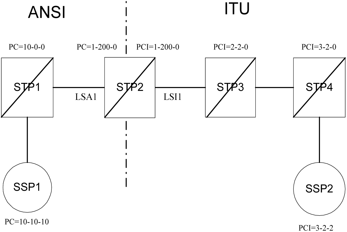
To obtain these measurement reports via the EAGLE interface, the value "gtwy" must be specified for the type parameter for the rept-meas command. For the rept-meas:type=gtwy command, support for STP, LNKSET, LSDESTNI and LSORIGNI as valid values for the type parameter is continued.
3.168 ITU International and National Spare Point Code (Release 34.0)
Description
The EAGLE allows a network operator to use the same Point Codes across two networks (either ITU-I or ITU-N). The feature also enables both ITU spare and non-spare traffic to be routed over the same linkset. The EAGLE uses the MSU Network Indicator (NI) to differentiate the same point code of one network from the other. In accordance with the SS7 standard, unique Network Indicator values are defined for ITU-I, ITU-N, ITU-I Spare, and ITU-N Spare Point Code types.
The EAGLE currently provides full support for four types of point codes:
- ANSI, ITU-National (NI=10binary)
- ITU-National 24-bit
- ITU-International (NI=00 binary)
- ITU National Spare PCs (NI=11 binary) can be primarily supported via a combination of the following two items:
- Support for ITU-National Spare can be set on a per linkset basis using the linkset NIS parameter. If set, the EAGLE will allow receipt of messages with NI=11binary on the designated linkset and will force all outgoing messages on that linkset to have NI=11binary.
- The Duplicate Point Code routing feature, combined with the Multiple Point Code Support feature, can be used to create a separate routing group for a National Spare Point Code network.
While these two functions can be combined to support ITU National Spare Point Code routing, there are limitations described as follows:- The EAGLE cannot distinguish between messages with different network indicators received over the same linkset. For example, the EAGLE will route a message with DPC = 1-1-1 (NI=10binary) the same way as a message with DPC = 1-1-1 (NI=11binary).
- Forcing the user to use the Duplicate PC Routing feature requires that all linksets in the system be placed in one of the defined groups.
The Spare Point Code Support feature addresses the above limitations and provides a new PC sub type named Spare that supports both the ITU-N Spare and ITU-I Spare Point Code feature.
Additionally, this feature requires a single linkset to support multiple outgoing network indicators (e.g. 11 binary, 00 binary). In turn, messages are routed according to the Point Code on the outgoing node that corresponds to the associated network indicator.
Hardware Requirements
There is no new hardware for this release.
Limitations
- This feature does not allow the EAGLE to MTP convert between National and National Spare Point Codes. Likewise, this feature does not allow the EAGLE to MTP convert between International and International Spare Point Codes.
- In the destination table, an ITU-I alias and an ITU-I Spare alias cannot be defined for the same Point Code, likewise an ITU-N alias and an ITU-N Spare alias cannot be defined for the same point code.
- The feature is not supported on the SEAS interface. Spare point codes are only supported for ITU point codes, and SEAS only supports ANSI point codes. Any Private ANSI point code provisioned using the standard EAGLE 5 SAS command line interface is not displayed by the SEAS VFY- command.
- ITU National and ITU National Spare Point Code are implemented as separate network domains that can co-exist within the same STP.
- Spare point codes are not supported for IPGWI sockets using TALI protocols. The spare point code feature may not be enabled if any application sockets have been provisioned on IPGWI cards.
- The existing implementation of Gateway Screening does not support Group Code (Duplicate Point Codes). Gateway Screening will also not support PPCs.
- The Spare Point Code and PPC prefix value, s- and p- do not apply to domain type point codes for ANSI and ITU-N24.
- ITU-N and ITU-N24 Point Codes cannot co-exist as SID Destination True Point Codes and therefore ITU-N Spare and ITU-N24 Point Codes cannot coexist as SID Destination True Point Codes.
- A single STPOPTS value (cnvcgdi) will be used to control message handling for ITU-I and ITU-I Spare messages when the CgPA PC does not have a required alias.
- A single STPOPTS value (cnvcgdn) will be used to control message handling for ITU-N and ITU-N Spare messages when the CgPA PC does not have a required alias.
- The existing implementation of the SRVSEL command interface to the SRVSEL table does not provide a way to separate MSU traffic for different ITU National Group Code networks. Therefore no provision is made for the SRVSEL command to control the separation of ITU spare and non-spare traffic. The SRVSEL table applies to the EPAP based features G-FLEX, INP, G-PORT, SMS Prepaid, and IS-41 to GSM Migration. Likewise, no provision is made for the GTTSEL command interface to the GTTSEL table to allow separation of ITU spare and non-spare traffic for EGTT, VGTT and MGTT.
3.169 ITU MTP Restart (Release 26.0)
Description
ITU MTP restart is a network management feature. It enables a restarting signaling point to bring a sufficient number of signaling links into the available state, and to update its routing tables before user traffic is restarted to the newly available signaling point.
This feature enables operators to implement ITU MTP Restart throughout their networks.
A central part of the restart procedure is the exchange of network status information between the restarting MTP and the adjacent nodes. In order for the procedure to make sense, the network status should not change significantly during this information exchange. As a consequence, there is an overall restart time defined for the node whose MTP is restarting as well as for the adjacent nodes. During this time, all activities within the node whose MTP is restarting as well as the adjacent nodes should be completed. This requires that the time available is used in an efficient way.
As a basis of the restart procedure, it is assumed that most of the signaling points within the network are accessible. Thus at the beginning of the restart procedure, all concerned routes are considered to be allowed, and the update of the network status is performed by the exchange of transfer-prohibited (TFP) and/or transfer-restricted (TFR) messages. The MTP restart procedure uses the Traffic Restart Allowed (TRA) message that is defined in section 15 of Q.704.
When an adjacent node has finished sending all relevant TFP and/or TFR messages to the node with the restarting MTP, it finally sends a TRA message that indicates that all relevant routing information has been transferred. Thus, at the node with the restarting MTP, the number of received TRA messages is an indication of the completeness of the routing data.
When the restarting MTP has completed all actions or when the overall restart time is over, it sends TRA messages directly to all of its adjacent nodes accessible via a direct link set. These messages indicate that the restart procedure is terminated and User traffic should be started.
Refer to the Database Administration Manual - SS7 for current information on this feature.
Upgrade Considerations
ITU MTP Restart introduces four new timers into the EAGLE's Level 3 Timer Table (IT18, IT19, IT20, IT21). There now resides 24 extra bytes of padding in the Level 3 Timer structure. With each timer taking 4 bytes, the total number of bytes needed for the new timers is 16 bytes.
The Level 3 Timer provides plenty of space to house the four new timers. Therefore during upgrade, only a conversion function will be required to handle the new table. This will convert the old structures without the timers to the new structures with the new timers, and set the new timers to their default values.
Measurements
The measurement MTPRESTS will be pegged when EAGLE restarts. This is an existing peg count that was previously used by ANSI restart, and will now be used for ANSI Only Restarts, ITU Only Restarts, and Mixed ITU/ANSI Restarts.
Limitations
-
The EAGLE will delay bringing into service Linksets that are not Restart Capable (
mtprse=no) until after Restart is Complete. -
While it is desirable to bring one link per linkset into service first when performing a Full Restart, because of the EAGLE's distributed architecture there is no advantage to this. Thus the EAGLE tries to align all links.
-
The restarting node should stop T18 when sufficient links are available, and enough TRA messages have been received. The EAGLE will stop T18 when all activated restart capable links are available, and it has received TRAs on all restart-capable linksets.
-
If all ITU links fail, but the EAGLE still has ANSI links available, the EAGLE will not perform a Full MTP Restart. In a Mixed ANSI/ITU network, the EAGLE will only perform a Full restart if all links, both ITU and ANSI, fail.
-
TFPs received on a link before the link is available at Level 3 will not be processed.
3.170 ITU SLS Enhancements (Release 26.0)
Description
The ITU SLS Enhancements feature gives EAGLE customers the ability to modify the method the EAGLE distributes traffic across ITU SS7 links.
EAGLE uses the LSB of SLS to load share between linksets of a combined linkset. ITU-T ISUP messages use a SLS that is obtained from the lower 4 bits of the CIC field representing the circuit being used.
CIC selection can be determined based on an odd/even method where a SSP uses either all odd CICs, or all even CICs, to help prevent “glaring” (i.e., 2 SSP attempting to seize the same trunk at the same time). This causes the LSB of the SLS to be fixed; if the LSB is fixed, inadequate load sharing occurs for the SS7 network. This situation can also occur within a single linkset (international), since EAGLE also uses the SLS (containing a fixed LSB) to select a link within a linkset.
Refer to the Database Administration Manual - SS7 for current information on this feature.
Restrictions
When two linksets are used as a combined linkset, they should have the same Other CIC Bit and Rotated SLS Bit settings. This is not enforced in the EAGLE, and there is no warning mechanism for incorrectly provisioned linksets and routes
Upgrade Considerations
-
Default values “Bit Rotation” and “Other Bit” must be set in LS tables during upgrade from Release 25 to 26.
-
The Use Other CIC Bit feature bit must be set to disabled during the upgrade.
3.171 ITU TCAP LRN Query (Release 40.0)
The ITU TCAP LRN Query (LRNQT) feature provides LNP support to an ITU TCAP LRN query and response, using the local routing number (LRN) method to support number portability. The translation type (TT) value for this query is configurable on the EAGLE 5 ISS.
3.171.1 Feature Control Requirements
The LRNQT feature has the following feature control requirements:
- FAK for part number 893-0263-01
- An LNP quantity feature that is greater than or equal to 24 Million must be turned on before the LRNQT feature can be enabled.
- A temporary FAK cannot be used to enable the feature.
- The feature cannot be turned off after it has been turned on.
- The feature must be turned on before any provisioning can occur.
3.172 ITUN-ANSI SMS Conversion (Release 37.0)
Description
The ITUN-ANSI SMS Conversion feature performs SMS address conversion for Registration Notification, SMS Request Return Result, and SMS Notification messages crossing the ITUN-ANSI network boundary to determine the destination point code in the destination network.
A FAK is required to enable the ITUN-ANSI SMS Conversion feature.
The ITUN-ANSI SMS Conversion feature modifies the SMS Address parameter in the TCAP/IS41 layer of the Registration Notification, SMS Request Return Result, and SMS Notification messages that cross the ITUN-ANSI network boundary. These messages are called identified messages and are modified per the destination network type. The SMS Address parameter in the identified messages must contain an ANSI or ITU-N point code value to enable the ITUN-ANSI SMS Conversion feature to process the messages.
Feature Control Requirements
The ITUN-ANSI SMS Conversion feature has the following feature control requirements:
- A FAK for part number 893-0153-01
- A temporary key cannot be used to enable the feature.
- After the feature has been turned on, it cannot be turned off.
Hardware Requirements
The ITUN-ANSI SMS Conversion feature requires DSM or TSM cards running the SCCP application
Limitations
The ITUN-ANSI SMS Conversion feature has the following limitations:
- ITU-I and ITUN-24 point codes are not supported.
- If DSM and TSM cards are down, the ITUN-ANSI SMS Conversion is not performed.
3.173 ITU-TFR Procedure (Release 26.1)
Currently, the EAGLE implements most, but not all, of the signaling route management capabilities defined in ITU-T recommendation Q.704, section 13. In particular, those capabilities defined as national options are not yet implemented.
The ITU TFR (International Telecommunication Union - Transfer Restricted) feature implements the transfer-restricted procedures defined in section 13.4 of Q.704Foot 1. The TFR procedure is used to redirect traffic away from a STP that is having problems routing traffic to a destination. When a STP determines that a destination is restricted, the STP will send, to its adjacent SPs, a TFR message containing an affected destination.
When a destination is restricted, the STP should not be used to route messages to the destination, even though it still has limited capability to do so. The TFR message is sent to the adjacent STPs to inform them of this condition.
The ITU TFR procedure can be enabled or disabled on a per ITU-N linkset basis (see ITU Gateway Measurements Enhancements (PR19536) (Release 26.05)). When the TFR procedure is enabled on a given linkset, TFR messages can be sent to the adjacent PC for the affected destinations.
Note:
The procedure does not apply to ITU-I linksets. The ANSI network employs its own similar version of the TFR procedure for ANSI linksets.
Upgrade Considerations
Default values for "ITU TFR Procedure" must be set in LS tables during upgrade to Release 26.1. Table 3-23 shows the tables requiring modifications during the upgrade process.
Table 3-23 Tables and Fields Affected by Upgrade
| Modified Tables | New Fields | Size | Value |
|---|---|---|---|
|
Linkset |
ITUTFR |
1 byte |
0 (off) |
New UIMs
This feature introduces a new UIM that is output in the event a TFR message is received on a ITU-N linkset that does not support the ITU TFR Procedure (parameter is OFF).
1233 MTP Invalid ITU TFR RCVD
When this occurs, the craftsperson should check if the itutfr parameter needs to be enabled for the linkset, or if the problem exists on an adjacent STP.
3.174 ITU/ANSI Conversion SLS Enhancement (Release 45.0)
The ITU/ANSI Conversion SLS Enhancement feature enhances the SLS Conversion algorithm to allow 4-bit ITU SLS to 8-bit ANSI SLS and 5-bit ANSI to 8-bit ITU SLS conversion. These conversions are supported for GT-routed messages.
3.175 J7 Feature (Release 45.1)
J7 Support Over SIGTRAN
The Eagle requires updates to be made in order to support the Japanese TTC (Telecommunication Technology Committee) standards, also known as J7. SIGTRAN specific implementation (SS7 networks) in Japan do not use standard ITU formats and procedures. The TTC has modified the ITU specifications to suit Japanese telecom signaling requirements.
Configurable J7 Point Code Format
- When the J7 feature is enabled, a new parameter is available in the STPOPTS table: PCN16FMT. This parameter has two values:
- 745 (UN-SNA-MNA format) (default)
- 547 (MNA-SNA-UN format)
Eagle displays command input, output, and UAM/UIMs for the ITUN16 point codes in the format specified by PCN16FMT when the J7 feature is enabled.
Extended J7 Requirements
- Feature is supported over M3UA/M2PA links only - the linkset configured for ITUN16 APC cannot have DS0, E1/T1 or ATM links.
- Eagle sets "Network Indicator" field to 0 for MSUs destined toward ITUN16 point code (
dpc=itun16). - ITUN16 linksets' default
sltsetuses a test pattern of 1177 as per JT-Q707. - Feature adds new point code type ITUN16 to support the 16 bit point code and MTP3 routing label formats used in Japanese networks.
- Feature adds support for JT-Q704/JT-Q707 procedures and messaging.
- Feature adds a new default Signalling Link Test set (sltset 3) for ITUN16 linksets for TTC SRT/SRA messaging.
- ITUN16 point code type is mutually exclusive with ANSI and ITUN24 point code types; thus, the Eagle node can support ITUN16 or ANSI/ITUN24 types but not both at the same time.
3.176 J7/TTC for J1-LSL Low Speed Link Support (Release 46.0)
The J7/TTC for J1-LSL Low Speed Link Support feature provides Japanese TTC MTP1/MTP2 variant support for Low Speed Links E1/T1 56kb/s and 64kb/s.
3.177 KSR Terminal Feature (Release 20.0)
The Keyboard Send Receive (KSR) feature enhances the EAGLE's dial-up administration functions by allowing faster throughput, since the control characters associated with the VT320 mode of terminal operation need not be transmitted.
The command used to modify the terminal configurations has a new parameter added to enable the KSR feature.
Footnote Legend
Footnote 1: ITU-T Recommendation Q.704, SS7 - Signalling network functions and messages, ITU-T, July 1996.