A ExAP or LSMS Network Integration
This chapter provides network integration information for Multi-Purpose Server (MPS) systems and Oracle Communications LSMS (Local Service Management Systems).
A.1 Introduction
The MPS platform can be configured as an Oracle Communications EAGLE LNP Application Processor (ELAP) or EAGLE Application Processor (EPAP) server. The MPS platform is an ELAP/EPAP system based on the E5-APP-B card platform.
The MPS provides an interface between the customer provisioning network and the EAGLE Service Module (SM) cards. As the customer’s data is updated, the MPS stores the data and updates the SM cards. An MPS is usually co-located with an EAGLE. If you need to install an MPS at a distance from the EAGLE, contact your My Oracle Support (MOS) for assistance.
The LSMS uses a NAS to backup system and application logs, as well as databases. The E5-APP-B NAS has a two-drive storage in RAID configuration to save the LSMS logs and database. The NAS is initially configured through the primary LSMS using tty serial terminal.
A.2 Network Overview
ExAP Network Connections
Figure A-1, Figure A-4 and their corresponding tables Table A-1 and Table A-2, respectively, illustrate the networks and how they are connected.
All networks, except the provisioning network, use internal connections in the MPS. Only the provisioning network connects to the customer’s network. All networks use TCP/IP and UDP/IP as the transport protocol.
- The provisioning network uses the Ethernet interface that typically connects to an external wide area network (WAN). This interface provides connectivity to the remote MPS system, an LSMS, or to a customer-provided provisioning system.
- The main SM Network uses the Ethernet interface that connects to the primary network port on all SM cards. This network has sufficient capacity to support up to 32 ( for EPAP, 18 for ELAP) SMs. The primary port on all SM cards runs at 1G.
Figure A-1 EPAP Network Connections
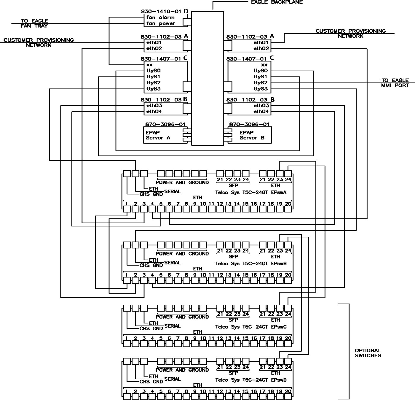
A. Adapter installed in the Upper position, odd slot
B. Adapter installed in the Lower position, odd slot
C. Adapter installed in the Lower and Upper position, even slot
D. Adapter installed on EAGLE backplane fan Connector (Power and Alarm)
Table A-1 EPAP Interconnect Table
| Cable Part Number | To | From |
|---|---|---|
| 830-1173-68 CAT 5 Crossover | Switch A port 1 | Switch B port 1 |
| 830-1173-68 CAT 5 Crossover | Switch A port 2 | Switch B port 2 |
| 830-1220-XX Serial Roll Over | Card / Server A, (P3) 830-1407-XX | Card /Server B, (P4) 830-1407-XX |
| 830-1220-XX Serial Roll Over | Card /Server A, (P4) 830-1407-XX | Card /Server B, (P3) 830-1407-XX |
| 830-1220-XX Serial Roll Over | Card /Server A, (P6) 830-1407-XX | Switch A Console Port |
| 830-1220-XX Serial Roll Over | Card /Server B, (P6) 830-14070-XX | Switch B Console Port |
| 830-1174-XX CAT 5 Straight | Card /Server A Port A (P2) 830-1102-03 | Customer Provisioning Network ETH01 |
| 830-1174-XX CAT 5 Straight | Card /Server B Port A (P2) 830-1102-03 | Customer Provisioning Network ETH01 |
| 830-1174-XX CAT 5 Straight | Card /Server A Port A (P3) 830-1102-03 | Switch A Port 3 ETH02 |
| 830-1174-XX CAT 5 Straight | Card /Server B Port A (P3) 830-1102-03 | Switch A Port 4 ETH02 |
| 830-1174-XX CAT 5 Straight | Card /Server A Port B (P2) 830-1102-03 | Switch B Port 3 ETH03 |
| 830-1174-XX CAT 5 Straight | Card /Server B Port B (P2) 830-1102-03 | Switch B Port 4 ETH03 |
| 830-1174-XX CAT 5 Straight | Card /Server A Port B (P3) 830-1102-03 | Switch A Port 5 ETH04 |
| 830-1174-XX CAT 5 Straight | Card /Server B Port B (P3) 830-1102-03 | Switch A Port 6 ETH04 |
| 830-1173-68 Optional | Switch A port 23 (CAT 5) Crossover | Switch C port 23 |
| 830-1173-68 Optional | Switch A port 24 (CAT 5) Crossover | Switch C port 24 |
| 830-1173-68 Optional | Switch B port 23 (CAT 5) Crossover | Switch D port 23 |
| 830-1173-68 Optional | Switch B port 24 (CAT 5) Crossover | Switch D port 24 |
| 830-1413-XX | Card Server A (P2) 830-1407-XX | EAGLE Backplane Fan Connector (J2 B) 830-1410-XX |
| 830-1413-XX | Card Server B (P2) 830-1407-XX | EAGLE Backplane Fan Connector (J3 A) 830-1410-XX |
| 830-1212-XX | Card Server B (P5) | EAGLE MMI Port Optional Cable, requires adapter 830-1423-XX |
The Synchronization Network uses the Ethernet interface that is on private LAN segment. This interface provides direct connectivity between MPS A and MPS B.
Figure A-2 Sync Network Redundancy (Eth04 used for Sync Network) Interconnectivity
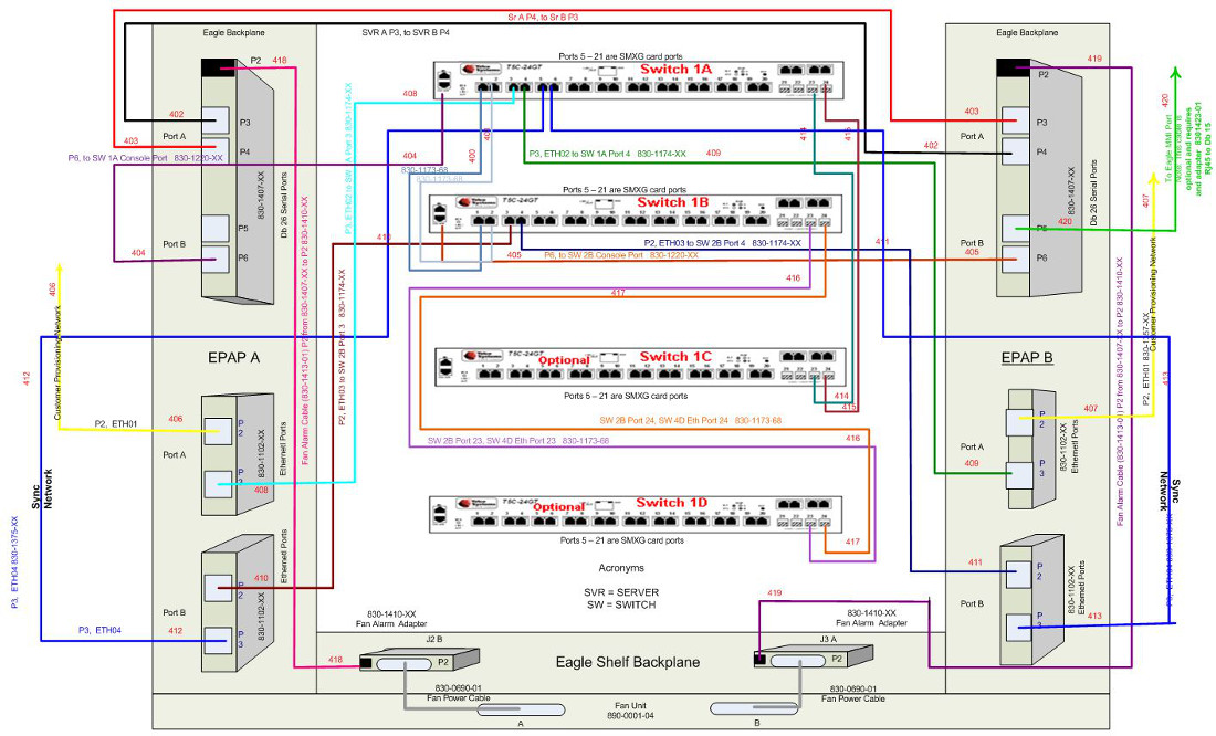
The backup SM Network uses the Ethernet interface that connects to the backup network port on all SM cards. This network has sufficient capacity to support up to 32 ( for EPAP, 18 for ELAP) SMs. The backup port on all SM cards runs at 1G.
Figure A-3 Default (Eth04 Used for Backup Provisioning Network) Interconnectivity
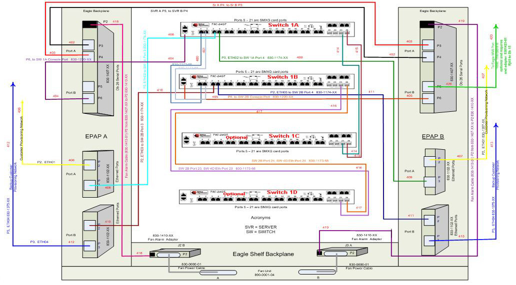
Figure A-4 ELAP Network Connections
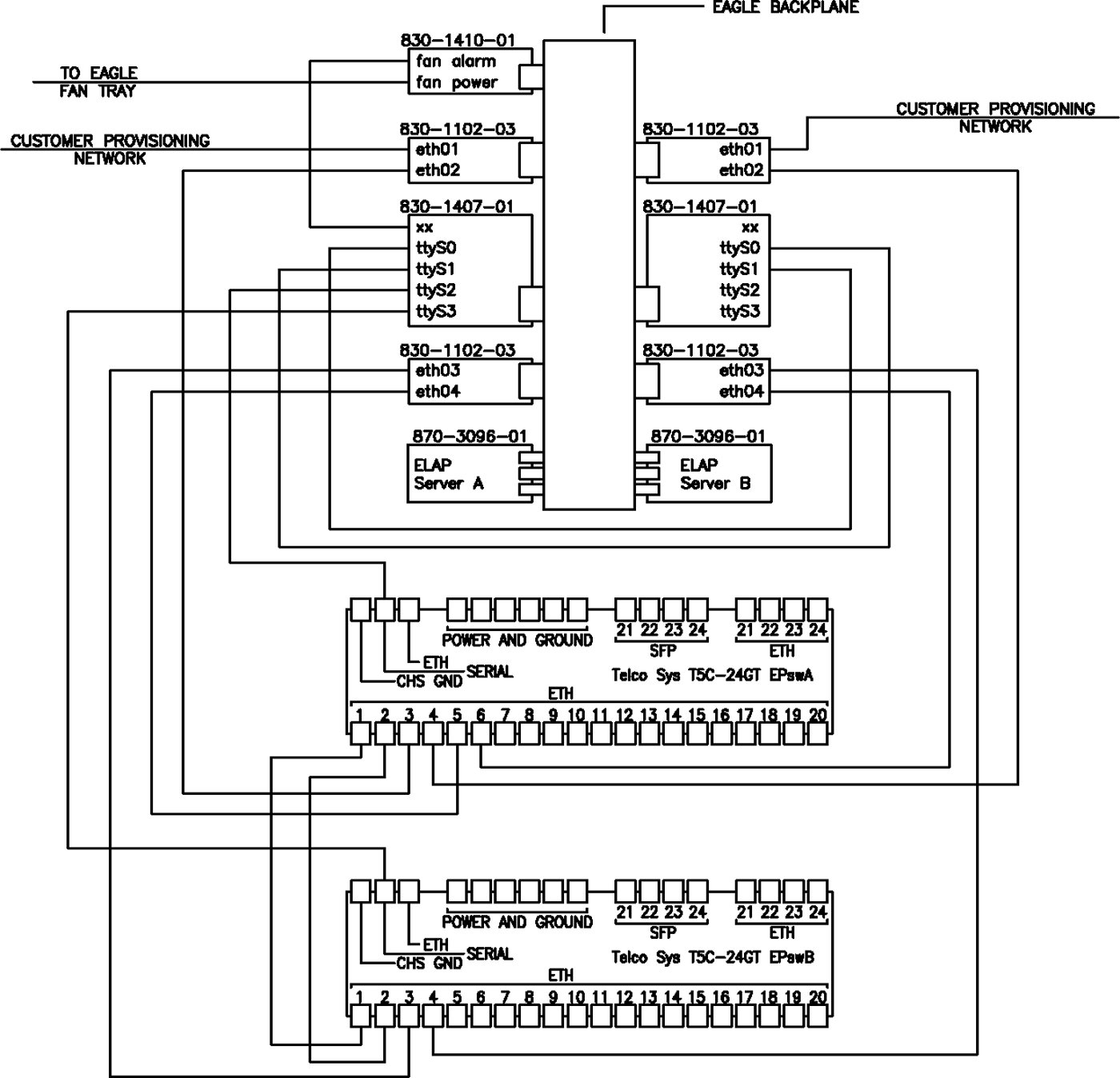
Table A-2 ELAP Interconnect Table
| Cable Part Number | To | From |
|---|---|---|
| 830-1173-68 CAT 5 Crossover | Switch A port 1 | Switch B port 1 |
| 830-1173-68 CAT 5 Crossover | Switch A port 2 | Switch B port 2 |
| 830-1220-XX Serial Roll Over | Card / Server A, (P3) 830-1407-XX TTYS0 | Card /Server B, (P4) 830-1407-XX TTYS1 |
| 830-1220-XX Serial Roll Over | Card /Server A, (P4) 830-1407-XX TTYS1 | Card /Server B, (P3) 830-1407-XX TTYS0 |
| 830-1220-XX Serial Roll Over | Card /Server A, (P5) 830-1407-XX TTYS2 | Switch A Console Port |
| 830-1220-XX Serial Roll Over | Card /Server A, (P6) 830-14070-XX Server A TTYS3 | Switch B Console Port |
| 830-1174-XX CAT 5 Straight | Card /Server A Port A (P2) 830-1102-03 ETH01 | Customer Provisioning Network ETH01 |
| 830-1174-XX CAT 5 Straight | Card /Server B Port A (P3) 830-1102-03 ETH02 | Switch A Port 3 ETH02 |
| 830-1174-XX CAT 5 Straight | Card /Server A Port A (P3) 830-1102-03 ETH02 | Switch A Port 4 ETH02 |
| 830-1174-XX CAT 5 Straight | Card /Server B Port A (P2) 830-1102-03 ETH03 | Switch B Port 3 ETH03 |
| 830-1174-XX CAT 5 Straight | Card /Server A Port B (P3) 830-1102-03 ETH04 | Switch A Port 5 ETH04 |
| 830-1174-XX CAT 5 Straight | Card /Server B Port B (P2) 830-1102-03 ETH01 | Customer Provisioning Network ETH01 |
| 830-1174-XX CAT 5 Straight | Card /Server A Port B (P2) 830-1102-03 ETH03 | Switch B Port 4 ETH03 |
| 830-1174-XX CAT 5 Straight | Card /Server B Port B (P3) 830-1102-03 ETH04 | Switch A Port 6 ETH04 |
| 830-1413-XX | Card Server A (P2) 830-1407-XX | EAGLE Backplane Fan Connector (J2 B) 830-1410-XX |
LSMS Network Connections
The Local Service Management System (LSMS) uses a NAS to backup system and application logs, as well as databases. The customer has the option of a Single Subnet configuration or Segmented configuration. The following figures and tables illustrate the different networks and how they are connected.
The LSMS Installation Kit includes a System Serial Number Label that should be applied to the frame's consolidated label. Refer to the "Label Application Instructions" that are included in LSMS Installation Kit for details.
Figure A-5 LSMS and NAS Single Subnet Connections
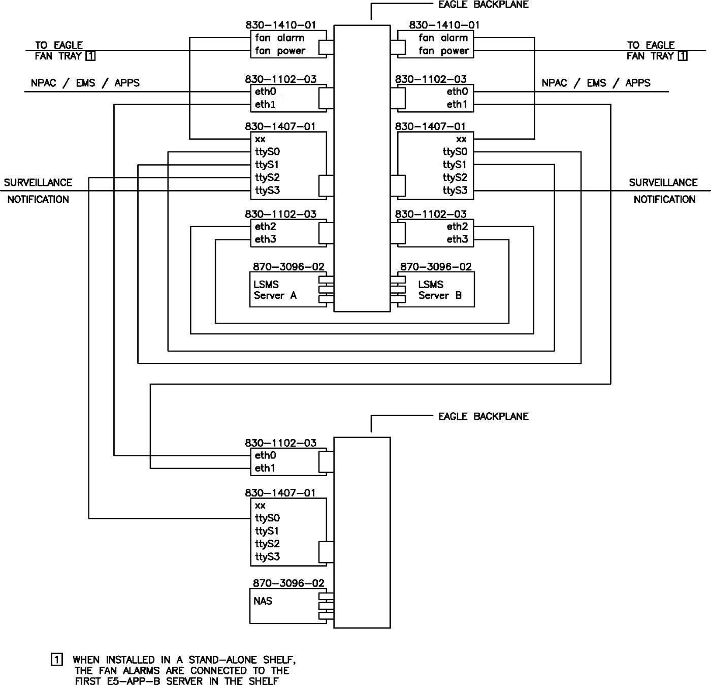
Table A-3 LSMS Single Subnet Interconnect Table
| Cable Part Number | To | From |
|---|---|---|
| 830-1174-XX CAT 5 Straight | Card /Server A Port A (P2)/ETH0 830-1102-03 | Customer Provisioning Network |
| 830-1174-XX CAT 5 Straight | Card /Server B Port A (P2)/ETH0 830-1102-03 | Customer Provisioning Network |
| 830-1174-XX CAT 5 Straight | Card /Server A Port A (P3) / ETH1 830-1102-03 | Card /NAS Port A (P2) / ETH0 830-1102-03 |
| 830-1174-XX CAT 5 Straight | Card /Server B Port A (P3) / ETH1 830-1102-03 | Card /NAS Port A (P3) / ETH1 830-1102-03 |
| 830-1174-XX CAT 5 Straight | Card /Server A Port B (P2) / ETH2 830-1102-03 | Card /Server B Port B (P2) / ETH2 830-1102-03 |
| 830-1174-XX CAT 5 Straight | Card /Server A Port B (P3) / ETH3 830-1102-03 | Card /Server B Port B (P3) / ETH3 830-1102-03 |
| 830-1220-XX Serial Roll Over | Card Server A (P3) 830-1407-XX | Card /Server B, (P4) 830-1407-XX |
| 830-1220-XX Serial Roll Over | Card Server A (P4) 830-1407-XX | Card /Server B, (P3) 830-1407-XX |
| 830-1220-XX Serial Roll Over | Card Server A (P5) 830-1407-XX | Card /NAS, (P3) 830-1407-XX |
| 830-1220-XX Serial Roll Over | Card Server A (P6) 830-1407-XX | Surveillance Notification |
| 830-1220-XX Serial Roll Over | Card Server B (P6) 830-1407-XX | Surveillance Notification |
| 830-1413-XX | Card Server A (P2) 830-1407-XX | EAGLE Backplane Fan Connector (J2 B) 830-1410-XX (P6) |
| 830-1413-XX | Card Server B (P2) 830-1407-XX | EAGLE Backplane Fan Connector (J3 B) 830-1410-XX (P6) |
Figure A-6 LSMS and NAS Segmented Connections
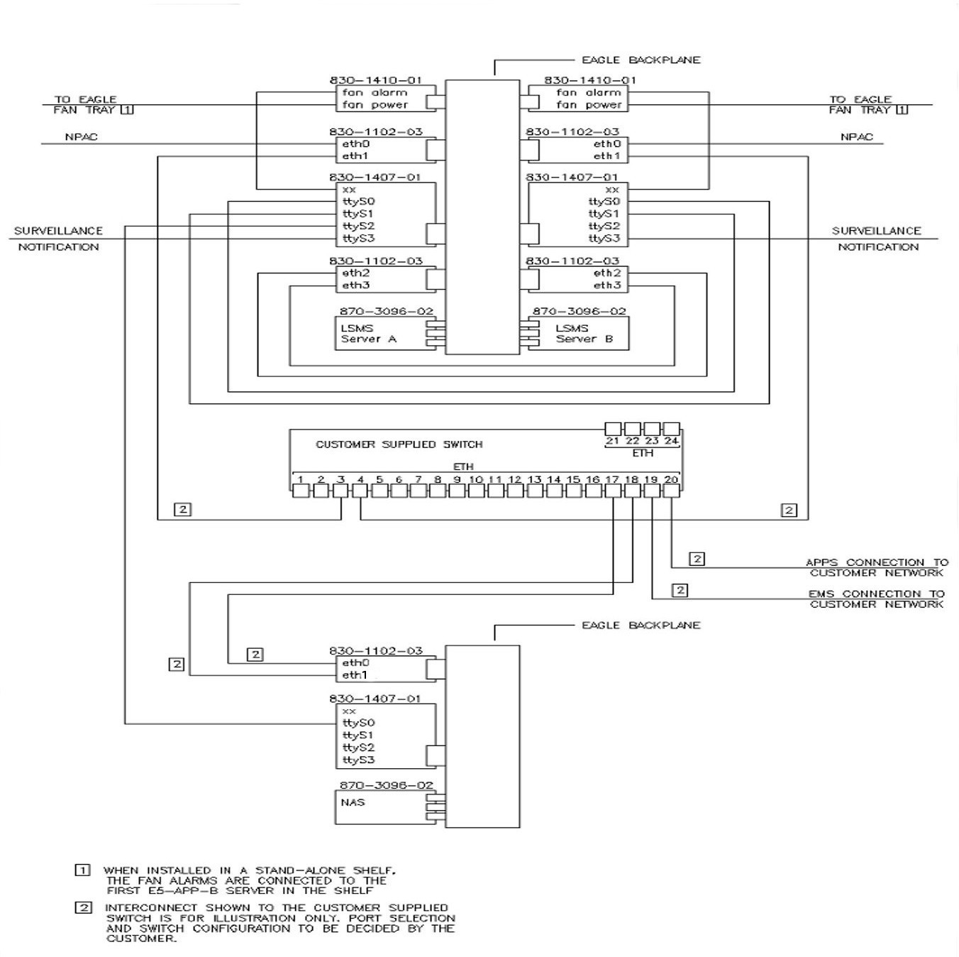
Table A-4 LSMS Segmented Interconnect Table
| Cable Part Number | To | From |
|---|---|---|
| 830-1174-XX CAT 5 Straight | Card /Server A Port A (P2) 830-1102-03 | NPAC |
| 830-1174-XX CAT 5 Straight | Card /Server B Port A (P2) 830-1102-03 | NPAC |
| 830-1174-XX CAT 5 Straight | Card /Server A Port A (P3) / ETH1 830-1102-03 | Customer Supplied Switch |
| 830-1174-XX CAT 5 Straight | Card /Server B Port A (P3) / ETH1 830-1102-03 | Customer Supplied Switch |
| 830-1174-XX CAT 5 Straight | Customer Supplied Switch | Card /NAS Port A (P2) / ETH0 830-1102-03 |
| 830-1174-XX CAT 5 Straight | Customer Supplied Switch | Card /NAS Port A (P3) / ETH3 830-1102-03 |
| 830-1174-XX CAT 5 Straight | Customer Supplied Switch | APPS |
| 830-1174-XX CAT 5 Straight | Customer Supplied Switch | EMS |
| 830-1174-XX CAT 5 Straight | Card /Server A Port B (P2) / ETH2 830-1102-03 | Card /Server B Port B (P2) 830-1102-03 |
| 830-1174-XX CAT 5 Straight | Card /Server A Port B (P3) / ETH3 830-1102-03 | Card /Server B Port B (P3) / ETH3 830-1102-03 |
| 830-1220-XX Serial Roll Over | Card Server A (P3) 830-1407-XX | Card /Server B, (P4)
830-1407-XX |
| 830-1220-XX Serial Roll Over | Card Server A (P4) 830-1407-XX | Card /Server B, (P3)
830-1407-XX |
| 830-1220-XX Serial Roll Over | Card Server A (P5) 830-1407-XX | Card /NAS, (P3)
830-1407-XX |
| 830-1220-XX Serial Roll Over | Card Server A (P6) 830-1407-XX | Surveillance Notification |
| 830-1220-XX Serial Roll Over | Card Server B (P6) 830-1407-XX | Surveillance Notification |
| 830-1413-XX | Card Server A (P2) 830-1407-XX | EAGLE Backplane Fan Connector (J2 B) 830-1410-XX (P6) |
| 830-1413-XX | Card Server B (P2) 830-1407-XX | EAGLE Backplane Fan Connector (J3 B) 830-1410-XX (P6) |
A.4 Network Configuration
SM and Sync Network addresses are configured to default values at ExAP or LSMS initialization and should not need to be changed. If they need to be changed for any reason, refer to sections “Network Connection” and “Configuration Menu” in Administration and LNP Feature Activation for ELAP, or Administration Guide for EPAP.
The provisioning network addresses are configured using the ExAP or LSMS user interface configuration menu; refer to “Configuration Menu” in Administration and LNP Feature Activation for ELAP or Administration Guide for EPAP.
A.5 Firewall and Router Filtering Considerations
If a firewall is installed in the provisioning network between the MPS systems or between the MPS system(s) and the provisioning system, it must be configured to allow selected traffic to pass.
For firewall protocol filtering for the various interfaces, see Administration Guide for EPAP, Administration and LNP Feature Activation for ELAP or Installation and Upgrade Guide for LSMS.