B IMF Network Integration
This chapter provides network integration information for the Integrated Message Feeder (IMF) system.
B.1 Introduction
Users have the ability to install the E5-APP-B card IMF System in an existing EAGLE frame. The E5-APP-B cards can be installed into any open slots. The single or dual switches can be installed into an open shelf location.
B.2 Network Overview
Network Connections
There are two kinds of network connections: Single Switch and Dual Switch. Table B-1 and Table B-2 illustrate the networks and how they are connected.
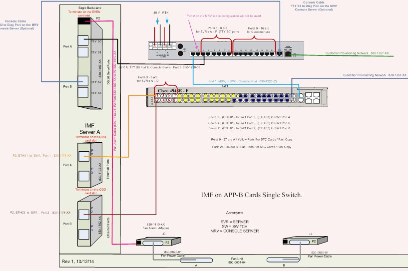
Table B-1 Single Switch Cabling Chart
| Cable Part Number | To | From |
|---|---|---|
| 830-1220-XX Serial Roll Over | Server A, TTY S2 Port, 830-1407-XX | Console Server Diag Port (Optional) |
| 830-1220-XX Serial Roll Over | Server A, TTY S0 Port, 830-1407-XX | Console Server, Port 3 |
| 830-1413-XX Fan Alarm Cable | Card/Server A, (P2) 830-1407-XX | EAGLE Backplane Fan Connector (J3), 830-1410-XX |
| 830-1174-XX CAT 5 Straight | Card/Server A Port A (P2) ETH01, 830-1102-XX | Switch 1, Port 1 |
| 830-1174-XX CAT 5 Straight | Card/Server A Port B (P2) ETH03, 830-1102-XX | Switch 1, Port 2 |
| 830-1220-XX Serial Roll Over | Switch 1 Console Port | Console Server, Port 1 |
| 830-1357-XX CAT 5 Straight | Console Server, Ethernet Port | Customer Provisioning Network |
| 830-1357-XX CAT 5 Straight | Switch 1, Port 47 | Customer Provisioning Network |
| Cabling for Servers B, C, D, E, F | ||
| 830-1174-XX CAT 5 Straight | Card/Server B Port A (P2) ETH01, 830-1102-XX | Switch 1, Port 3 |
| 830-1174-XX CAT 5 Straight | Card/Server B Port B (P2) ETH03, 830-1102-XX | Switch 1, Port 4 |
| 830-1174-XX CAT 5 Straight | Card/Server C Port A (P2) ETH01, 830-1102-XX | Switch 1, Port 5 |
| 830-1174-XX CAT 5 Straight | Card/Server C Port B (P2) ETH03, 830-1102-XX | Switch 1, Port 6 |
| 830-1174-XX CAT 5 Straight | Card/Server D Port A (P2) ETH01, 830-1102-XX | Switch 1, Port 7 |
| 830-1174-XX CAT 5 Straight | Card/Server D Port B (P2) ETH03, 830-1102-XX | Switch 1, Port 8 |
| STC Cards
(E5-ENET-B)
(2) 830-1174-XX cables per card. (2) 830-1102-XX cable adapters per card. Adapters will be plugged onto each card on the backplane (Port A&B) Cables will plug into the (P3) port on each adapter. |
||
| Fast Copy
(E5-ENET-B)
(2) 830-1174-XX cables per card. Cables will plug into the (P2) port on both existing adapters. |
||
| For the STC or Fast-Copy cards, the A Port of each card will be plugged into the Yellow switch ports (ports 9-27), and the B ports on the Blue ports (ports 28-46) in the single switch configuration. | ||
Figure B-1 IMF Interconnect Single Switch Configuration
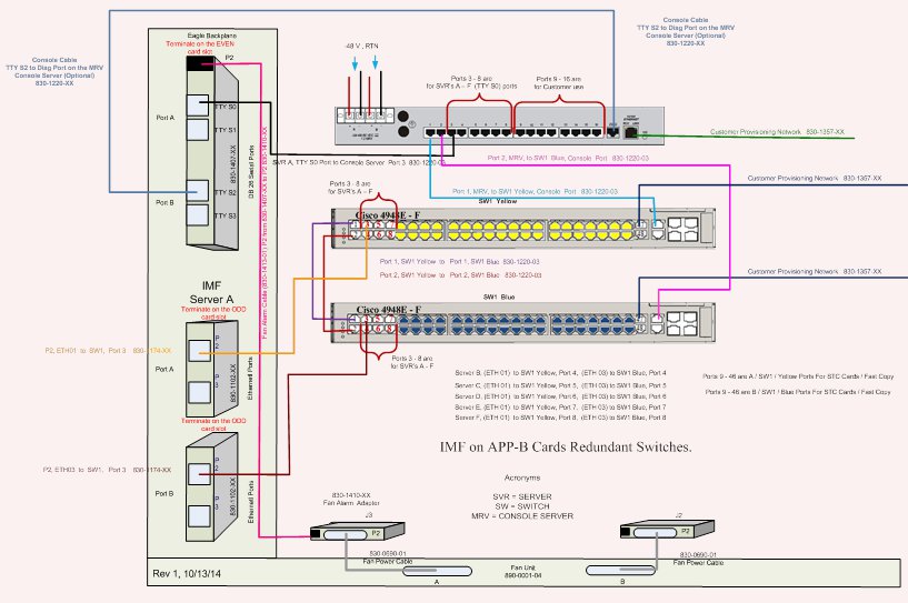
IMF Dual Switch Configuration
Table B-2 Dual Switch Cabling Chart
| Cable Part Number | To | From |
|---|---|---|
| 830-1220-XX Serial Roll Over | Server A, TTY S2 Port, 830-1407-XX | Console Server Diag Port (Optional) |
| 830-1220-XX Serial Roll Over | Server A, TTY S0 Port, 830-1407-XX | Console Server, Port 3 |
| 830-1220-XX Serial Roll Over | SW1 Yellow Port 1 | SW1 Blue, Port 1 |
| 830-1220-XX Serial Roll Over | SW1 Yellow Port 2 | SW1 Blue, Port 2 |
| 830-1413-XX Fan Alarm Cable | Card/Server A, (P2) 830-1407-XX | EAGLE Backplane Fan Connector (J3), 830-1410-XX |
| 830-1174-XX CAT 5 Straight | Card/Server A Port A (P2) ETH01, 830-1102-XX | SW1 Yellow, Port 3 |
| 830-1174-XX CAT 5 Straight | Card/Server A Port B (P2) ETH03, 830-1102-XX | SW1 Blue, Port 3 |
| 830-1220-XX Serial Roll Over | SW1 Yellow, Console Port | Console Server, Port 1 |
| 830-1220-XX Serial Roll Over | SW1 Blue, Console Port | Console Server, Port 2 |
| 830-1357-XX CAT 5 Straight | Console Server, Ethernet Port | Customer Provisioning Network |
| 830-1357-XX CAT 5 Straight | SW1 Yellow, Port 47 | Customer Provisioning Network |
| 830-1357-XX CAT 5 Straight | SW1 Blue, Port 47 | Customer Provisioning Network |
| Cabling for Servers B, C, D, E, F | ||
| 830-1174-XX CAT 5 Straight | Card/Server B Port A (P2) ETH01, 830-1102-XX | SW1 Yellow, Port 4 |
| 830-1174-XX CAT 5 Straight | Card/Server B Port B (P2) ETH03, 830-1102-XX | SW1 Blue, Port 4 |
| 830-1174-XX CAT 5 Straight | Card/Server C Port A (P2) ETH01, 830-1102-XX | SW1 Yellow, Port 5 |
| 830-1174-XX CAT 5 Straight | Card/Server C Port B (P2) ETH03, 830-1102-XX | SW1 Blue, Port 5 |
| 830-1174-XX CAT 5 Straight | Card/Server D Port A (P2) ETH01, 830-1102-XX | SW1 Yellow, Port 6 |
| 830-1174-XX CAT 5 Straight | Card/Server D Port B (P2) ETH03, 830-1102-XX | SW1 Blue, Port 6 |
| 830-1174-XX CAT 5 Straight | Card/Server E Port A (P2) ETH01, 830-1102-XX | SW1 Yellow, Port 7 |
| 830-1174-XX CAT 5 Straight | Card/Server E Port B (P2) ETH03, 830-1102-XX | SW1 Blue, Port 7 |
| 830-1174-XX CAT 5 Straight | Card/Server F Port A (P2) ETH01, 830-1102-XX | SW1 Yellow, Port 8 |
| 830-1174-XX CAT 5 Straight | Card/Server F Port B (P2) ETH03, 830-1102-XX | SW1 Blue, Port 8 |
| STC Cards
(E5-ENET-B)
(2) 830-1174-XX cables per card. (2) 830-1102-XX cable adapters per card. Adapters will be plugged onto each card on the backplane (Port A&B) Cables will plug into the (P3) port on each adapter. |
||
| Fast Copy
(E5-ENET-B)
(2) 830-1174-XX cables per card. Cables will plug into the (P2) port on both existing adapters. |
||
| The A Port of each card will be plugged into the Yellow switch ports, and the B Port of each card will be plugged into the Blue switch ports. | ||
Figure B-2 IMF Interconnect Dual Switch Configuration