2 Safety and Pre-Installation Requirements
This chapter lists general safety instructions that readers should be familiar with and site requirements that should be verified before installing Oracle Communications E5-APP-B cards into an EAGLE shelf.
2.1 Introduction
This chapter presents general safety considerations to be kept in mind when installing or replacing Oracle Communications products, a listing of regulatory compliance statements and certifications that Oracle Communications products support, and site requirements for installing Oracle Communications products.
2.2 Safety Information
Safety icons and text are used throughout Oracle Communications guides to warn the reader of the potential of personal injury, service interruption, and equipment damage.
Before beginning any procedure described in this guide, ensure that you are familiar with each of the following safety admonishments. Additional safety admonishments may be included, or repeated, for specific procedures.
topple:
Always read and understand instructions completely before working on, moving, raising or lowering the frame, any portion of the frame, or attachments to the frame or equipment.topple:
Never try to unpack any frame from the shipping container without at least two people to steady any movement of the frame and related components. At least two people are required to safely move and position any frame.topple:
Never pull out the shelf of any frame that is not anchored properly. Some frames are required to be attached to overhead ladder racks before shelves are extended.DANGER:
No commercially AC powered equipment may be used or placed within 7 ft. of –48V equipment. AC powered equipment within 7 ft. of –48V equipment may create a shock or current loop that can be severely hazardous to personnel and equipment.DANGER:
Do not wear metal, chains, rings, watches, or jewelry or carry exposed metal, keys or tools in pockets when working on system equipment or other related electrostatic-sensitive components. Always wear a wrist strap or other electrostatic protection when handling printed circuit boards and other electrostatic-sensitive devices.warning:
Do not leave or allow unused metal objects, such as screws or washers, to remain anywhere within the equipment. Remove all unused material from the equipmentwarning:
Do not allow any metal shavings to remain in the equipment area. Metal Shavings may result from over tightened screws or bolts. These small metal particles are hazardous to electronic equipment. Be careful not to over tighten screws or bolts.warning:
Do not use tie wraps on or above the top traverse arms on a frame. Always trim tie wrap flush and turn the trimmed tie wrap to the rear of the cable.Caution:
All personnel associated with the installation of these systems must adhere to all safety precautions and use required protection equipment, to avoid the possibility of injury to personnel, service degradation, and/or service interruption.Caution:
These systems have redundant power supplies to allow service during normal maintenance. When repairs require a total power disconnect, both input supply sources must be disconnected. This causes service interruption and takes down the systems.Caution:
This equipment has a connection between the earthed conductor of the DC supply circuit and the earthing conductor.Caution:
The Branch Circuit Overcurrent Protection shall be rated minimum -48V, maximum 60A.Caution:
Equipment is to be installed in restricted access areas in accordance with articles 110-16, 110-17, and 110-18 of the National Electric Code, ANSI/NFPA 70.Caution:
A readily accessible disconnect device that is suitable, approved, and rated shall be incorporated in the field wiring.Caution:
Connect to a reliably grounded SELV source which is reliably earthed and electrically isolated from the AC source.Caution:
Use only listed closed loop connectors for connection to the supply.Note:
Use a minimum of 26 AWG telecommunications line cord for connection to the modem.2.3 Regulatory Compliance and Certification
Oracle Communications products are tested to meet the following regulatory standards:
- Network Equipment Building System (NEBS) level 3 as listed in Telcordia SR-3580.
- Applicable Telcordia Electromagnetic Compatibility and Electrical Safety requirements in GR-1089-CORE.
- Applicable Physical Protection requirements in GR-63-CORE.
- Relevant directives and harmonized standards in support of the products Compliance European (CE) mark required in Europe. Figure 2-1 shows the mark used to indicate this compliance.
Figure 2-1 European Directives CE Mark

- Relevant standards in ElectroMagnetic Compatibility (EMC) directive 2004/108/EC.
- Relevant standards in Safety directive 2006/95/EC, supported by Certified Body (CB) Test Certificates issued by the National Certification Body as tested to IEC 60950 with national differences for participating countries .
- Underwriters Laboratories (UL) listed under UL File E200146 for USA and c-UL for Canada. Figure 2-2 shows the mark used to indicate this compliance.
Figure 2-2 Combined UL Mark for the United States and Canada

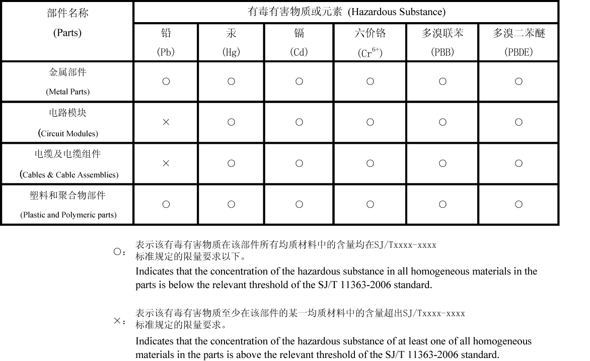
- Relevent standards in SJ/T 11363-2006 for limits of certain hazardous substances.
Figure 2-3 Hazardous Substances
2.4 Pre-Installation Site Requirements
Before installing E5-APP-B cards into an EAGLE shelf, make sure that the requirements described in both of the following sections have been met.
2.4.1 Generic Site Requirements
Ensure that the site where the product will be installed conforms to the specifications listed in the following sections. These specifications are standard telephony industry requirements for equipment installation.
Fire Protection
Local fire protection codes must be satisfied in the equipment room where the system is to be located.
Environmental Requirements
Oracle Communications products are designed for environments that have temperature and humidity controls. Temperature and humidity controls must be activated as quickly as possible for equipment to operate at an optimum level.
When temperature and humidity controls fail, the equipment has been tested to operate within the following ranges:
-
-
5˚ C to 40˚ C (41˚ F to 104˚ F) for normal operation
-
-5˚ C to 50˚ C (23˚ F to 122˚ F) for no more than 96 hours in duration and at elevations less than 1800 meters
-
-5˚ C to 50˚ C (23˚ F to 122˚ F) for storing the product
-
-
-
5% to 85% non-condensing for normal operation
-
5% to 90% non-condensing (but not to exceed 0.024 kilograms of water per kilogram of dry air) for no more than 96 hours in duration and at elevations less than 1800 meters
-
Oracle Communications products are tested to operate at an elevations within the following range:
-
Minimum: 60 meters below sea level at ambient temperature of 30˚ C (86˚ F)
-
Maximum: 4000 meters above sea level at ambient temperature of 40˚ C (104˚ F)
HVAC Requirements
Oracle Communications products are designed to bring cool air in from the bottom front and exit heated air out the top rear of the installed equipment.
The required HVAC (Heating, Ventilation, and Air Conditioning) capacity depends on the installed equipment. To calculate needed HVAC capacity, determine the total wattage of the installed equipment and use the following formula:
BTUs/hr. = watts x 3.413
The amount of power required by frame components is found at: DC_PowerReqmts.pdf.
The E5-APP-B card must be installed in a fully populated EAGLE shelf with a fan tray and air management cards, if necessary.
Lighting
Adequate lighting should be provided in the room where the equipment is to be located. Lighting fixtures must be far enough from the equipment and cables to prevent heat damage and to allow safe access to equipment and cables.
Earthquake Resistance
All Oracle Communications system configurations are designed to assure that the system remains operational during and after an earthquake, even when the system is located on the upper floors of a zone 4 central office.
Space Requirements
Provide space as described in Generic Site Requirements. These space requirements provide for Oracle Communications equipment installed in a 23-inch heavy-duty frame, which measures 7 feet high. Separator panels and end panels add to the width of multiple frame systems.
Table 2-1 Space Requirements
| Building Area | Dimensions | Notes |
|---|---|---|
|
Halls |
4.5 feet wide by 8 feet tall (1.4 meters wide by 2.4 meters tall) |
To provide a clear, uncluttered route for moving equipment between the loading/receiving dock and the planned system location |
|
Frame location |
30 inches wide by 24 inches deep (76.2 cm wide by 60.96 cm deep) |
Floor area recommended for one Oracle Communications frame (multiply by the number of frames listed on the Initial Sales Order) Total area per frame = 720 square inches (5.0 square feet) (0.465 square meters) |
|
Side aisles |
4 feet (1.2 meters) |
To allow maneuvering frames into place and provide ample work space around the equipment |
|
Front and rear access |
3 feet 6 inches (107 cm) |
From walls or other frames |
|
Side access |
12 inches (31 cm) |
From walls or other frames |
In addition, when planning the installation, be sure to take into account spare hardware storage, modems, terminals, printers, cross connect panels, and all other items that might require space in a system.
Floor Loading
Oracle Communications products installed in heavy-duty control or extension frames are designed for installation on raised or solid floors, which are recommended to have a distributed load capacity of no less than 100 pounds per square foot (504 kg/m2) and a maximum weight of EAGLE 5 ISS 850 lbs (386 kg).
Use the following equation to calculate the floor loading:
Distributed floor capacity = Total equipment weight/floor area
2.4.2 Grounding and Power Requirements
Before installing E5-APP-B cards into an EAGLE shelf, make sure that the grounding and power requirements in the appropriate following sections have been met.
Grounding Requirements
Oracle Communications systems operate as digital isolated ground plane systems in a central office environment and require a single connection to the central office ground window. The system’s ground cables must provide the sole grounding connection between the entire system and the central office grounding.
warning:
Always install an isolator pad between the frame and ground. Oracle Communications frames are shipped with isolator pads to completely isolate the frames from ground. If a non-Oracle Communications frame is used, an isolator pad must be provided.The system can use three types of grounding paths:
-
Battery return
The battery return grounding path is the return path for all –48VDC loads in the system. This path is isolated from other system grounds and connects to the rest of the central office through the –48VDC return connections located on the breaker panels of each frame.
-
Logic Ground
Some system types require connection to a logic ground. The logic ground path provides a common voltage reference point between all circuit boards of a system. Each connection terminates to the system ground. The logic ground path is shown on your system’s interconnect drawing. The logic ground path does not carry current.
-
Frame/shelf ground
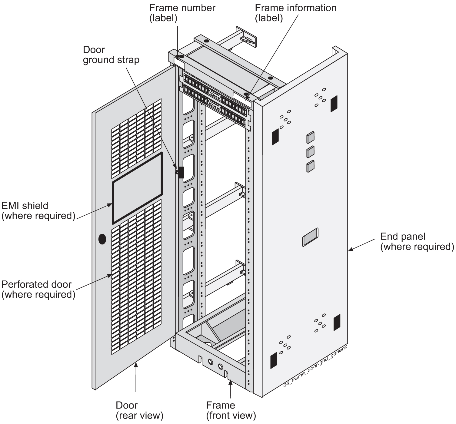
The frame/chassis ground path provides a low impedance connection for all metal parts of the entire system, including the frame, doors, shelves, and end panels. Each frame/chassis connection within the system lineup terminates to the frame and connects to the main ground by way of Htaps, #6 American Wire Gauge (AWG) to 1/0 cable.
Note:
The frame/chassis ground path does not carry current.For products installed in a frame, the doors installed are grounded to the frame through a two-hole lug ground wire and through a screw-down latch. Figure 2-4 shows a cutaway view example of an open frame door showing the door ground strap.
Figure 2-4 Door Grounding Strap Placement
EAGLE Shelf Power Requirements
Note:
EAGLE cannot provision two E5-APP-B cards running the same application in slots with the same power sources in different frames unless the force=yes parameter is used.