A.2 CISCO SWITCH CONFIGURATION
Note: Contact My Oracle Support atleast 48 hours before the scheduled start of the switch configuration process, to obtain the Enable secret key.
Table A-2 CISCO SWITCH CONFIGURATION
| STEP # | This procedure Configures the Cisco Switches on an Installed APPB ELAP Server Pair. Check off (✓) each step as it is completed. Boxes have been provided for this purpose under each step number.If this procedure fails, contact My Oracle Supportand ask for ASSISTANCE. | |
|---|---|---|
|
1. 1. ☐ |
Make the cross-over cable connections. |
NOTE: THIS IS IMPORTANT CONNECT the cross-over cable from Port 1 of Switch1A to Port 1 of Switch1B. DISCONNECT the cross-over cable from Port 2 of Switch1A to Port 2 of Switch1B. Similarly while Configuring Switch1C and Switch1D Disconnect the cable from port 24 and connect back post configuration done. Please make a note that the switch configuration should only be attempted by a skilled technician and not all. All uplinks should be removed while switch configuration. There should not be any loop in the switches during their configuration. Switch1B must be configured first. NOTE: the following should be the sequence of switch configuration. Switch1B > Switch1A > Switch1C > Switch1D Make sure to enable and start tftp service by using following commands if not started earlier :- |
|
2. ☐ |
Do minicom to enter the cisco switch console. Command – “minicom switch1A” for the console cable connected to MPS-A and for console cable connected to MPS-B use “minicom switch1B”. |
|
|
3. 3. ☐ |
MPS X: Do not enter in the initial config dialog in the freshly connected cisco switch. |
Autoinstall will terminate if any input is detected on console
|
|
4. 4. ☐ |
MPS X: Enter an Enable secret key :- NOTE: Please note that this key is predetermined. If the key to be entered here is not known contact My Oracle support for assistance |
|
|
5. 5. ☐ |
MPS X: Press 0 and enter |
|
|
6. 6. ☐ |
MPS X: Initial configuration building done. |
|
|
7. 7. ☐ |
MPS X: Write “enable” and provide the password set in step 4 |
|
|
8. 8. ☐ |
MPS X: Once the switch is enabled to take configuration > sign changes to the # sign |
|
|
9. 9. ☐ |
MPS X: Write command – “Configure terminal with no logging enabled” |
|
|
10. 9. ☐ |
MPS X: Exit from the minicom |
Ctrl+A and then Press Z. This will exit the minicom console and you will come back to the server terminal. |
|
11. 11 ☐ |
MPS B: Navigate to the Network Configuration Menu. |
On the platcfg Main Menu, select Network Configuration and press [ENTER]. 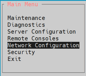 |
|
12. 11 ☐ |
MPS B: Navigate to the Configure Switch menu |
On the Network Configuration menu, select Configure Switch and press [ENTER]. 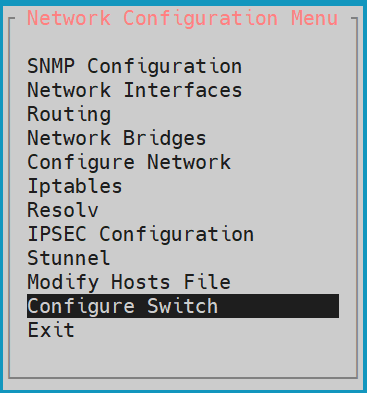 |
|
13. 13 ☐ |
MPS B: Select Switch1B. |
On the Select Switch Menu, select Switch1B – Second Switch in Frame 1 and press [ENTER]. 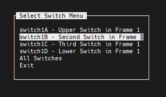 |
|
14. 14 ☐ |
MPS B: Confirm Switch 1B Configuration. |
Select Yes and press [ENTER] to configure Switch 1B. 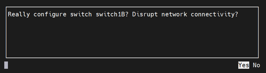 |
|
15. ☐ |
MPS B: Switch Configuration Screen. |
Configuring the switch takes about 10 minutes, once completed press any key to continue and then click Exit.  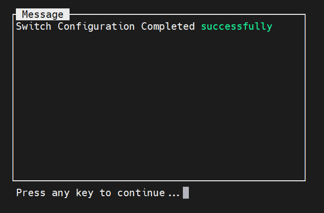 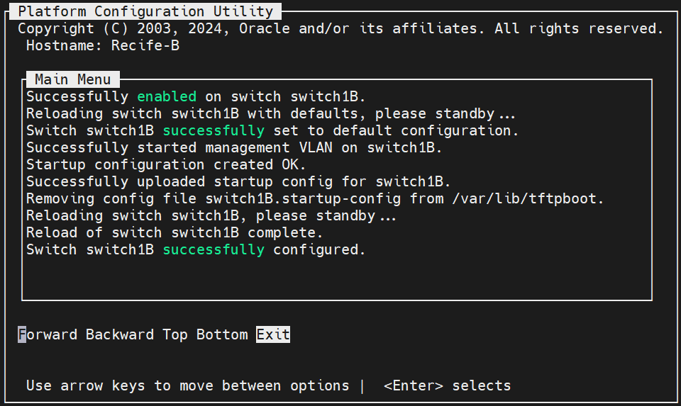 |
|
16. 14. ☐ |
MPS X: Similarly need to configure all other connected cisco switches. |
Use the steps mentioned from step 2 - 15. Make sure to select the proper switch as per the switch location for eg Switch1A,switch1C etc. NOTE: the following should be the sequence of switch configuration. Switch1B > Switch1A > Switch1C > Switch1D |
|
17. 15. ☐ |
Connect the cross-over cable from Port 2 of Switch1A to Port 2 of Switch1B. |
 |
|
18. 16. ☐ |
Ping to Confirm connectivity. Note: Ip address 192.168.2.1 associated with Switch1A , ip address 192.168.2.2 associated with Switch1B , ip address 192.168.2.3 with Switch1C and ip address 192.168.2.4 with Switch1D. |
Ping from all the newly connected switches to the mentioned IP address (192.168.2.1, 192.168.2.2, 192.168.2.3, 192.168.2.4, 192.168.2.100, 192.168.2.200), till you see an 100% success rate. |
|
19. 17. ☐ |
Procedure complete. |
Procedure is complete. |