3.5.1 Procedure 11 Switch Configuration
Table 3-15 Procedure 11 Switch Configuration
| STEP # | This procedure Configures the Switches of a newly installed ELAP Server Pair. Check off (✓ )each step as it is completed. Boxes have been provided for this purpose under each step number. IF THIS PROCEDURE FAILS, CONTACT THE ORACLE TECHNICAL SERVICES AND ASK FOR ASSISTANCE. | |
|---|---|---|
|
1. ☐ |
Make the cross- over cable connections. |
NOTE: THIS IS IMPORTANT CONNECT the LAG cable from Port 1 of Switch1A to Port 1 of Switch1B. DISCONNECT the LAG cable from Port 2 of Switch1A to Port 2 of Switch1B.
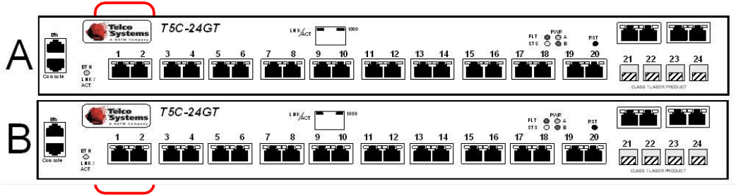 NOTE: The switch configuration should only be attempted by a skilled technician. All uplinks should be removed while switch configuration. There should not be any loop in the switches during their configuration. |
|
2. ☐ |
MPS A: Console login. |
Login using serial console.
|
|
3. ☐ |
MPS A: Start services for switch configuration |
Change the startup information for tftp:
Change the startup information for xinetd:
Start xinetd:
Start and Enable tftp service:
Check if both xinetd and tftp are up and running:
|
|
4. ☐ |
MPS A: Verify the bond0 configuration. |
Verify that the eth03 is the default primary port of the bond0:
|
|
5. ☐ |
MPS A: Set the permissions for BiNOS- T5CL3_24G- G_v8.6.R6.2.bin |
|
|
6. ☐ |
MPS A: Start platcfg utility. |
|
|
7. ☐ |
MPS A: Navigate to the Network Configuration Menu. |
On the platcfg Main Menu, select Network Configuration and press [ENTER]. 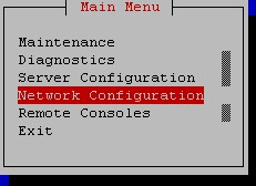 |
|
8. ☐ |
MPS A: Navigate to the Configure Switch Menu. |
On the Network Configuration menu, select Configure Switch and press [ENTER]. 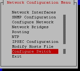 |
|
9. ☐ |
MPS A: Select to configure “switch1B – Lower Switch in Frame 1” and press Enter. |
On the Select Switch Menu, select “switch1B – Lower Switch in Frame 1” and press [ENTER]. 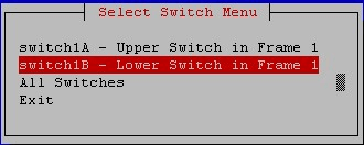 |
|
10. ☐ |
MPS A: Confirm Switch Configuration. |
Select Yes and press [ENTER] to configure Switch 1B. 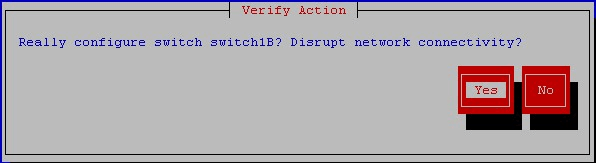 |
|
11. ☐ |
MPS A: Switch Configuration Screen. |
Configuring the switch takes about 10 minutes, once complete press [ENTER] to continue. 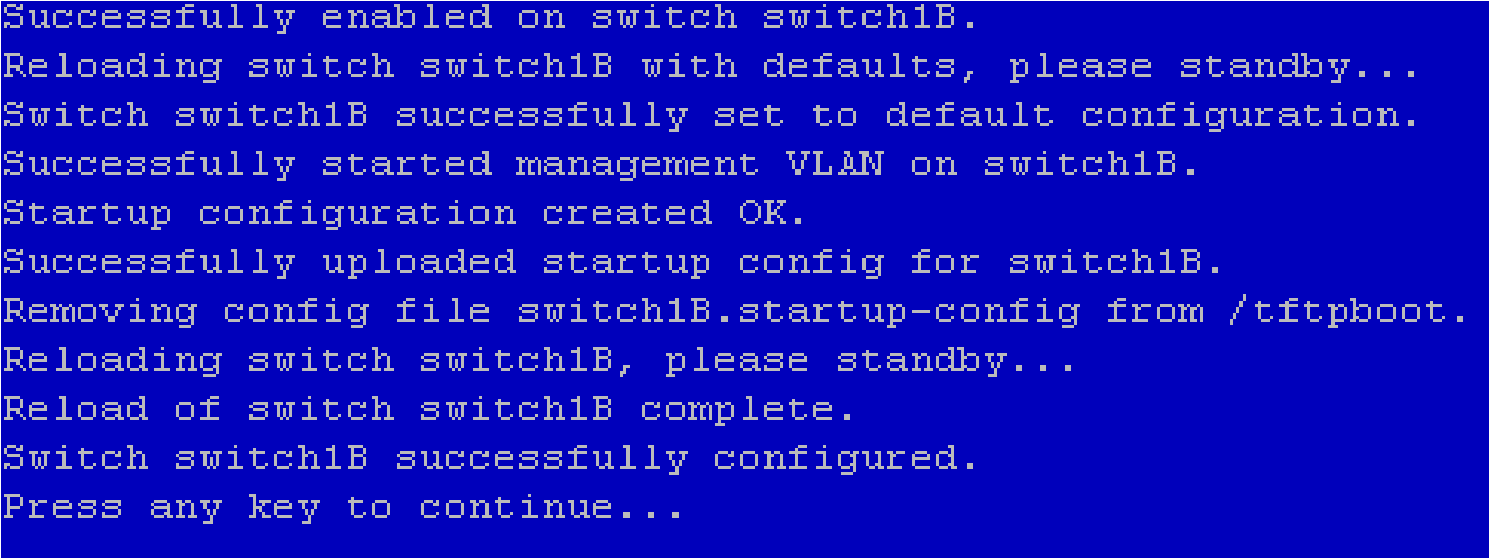 |
|
12. ☐ |
MPS A: Switch Configuration completion screen. |
The switch configuration completion screen is displayed. Press [ENTER] to continue. 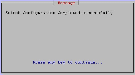 |
|
13. ☐ |
MPS A: Select to configure “switch1A – Upper Switch in Frame 1” and press Enter. |
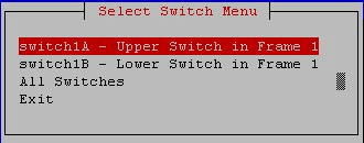 On the Select Switch Menu, select “switch1A – Upper Switch in Frame 1” and press [ENTER]. |
|
14. ☐ |
MPS A: Confirm Switch Configuration. |
Select Yes and press [ENTER] to configure Switch 1A. 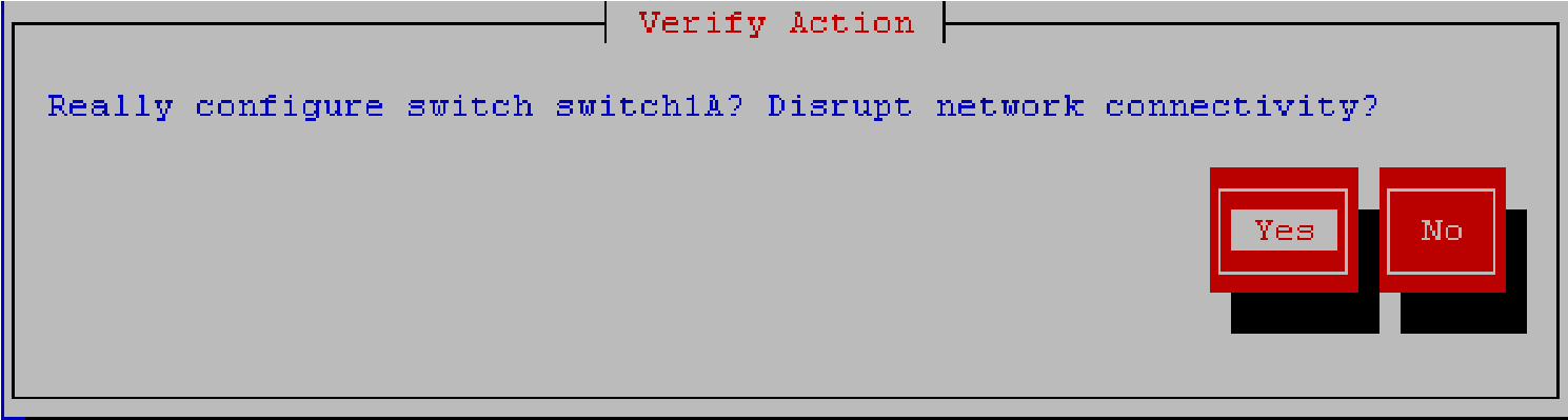 |
|
15. ☐ |
MPS A: Switch Configuration Screen. |
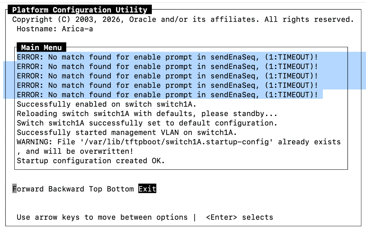 Configuring the switch takes about 10 minutes. Once complete, press [ENTER] to continue. |
|
16. ☐ |
MPS A: Switch Configuration completion screen. |
The switch configuration completion screen is displayed. Press [ENTER] to continue. |
|
17. ☐ |
MPS A: Exit out of platcfg. |
|
|
18. ☐ |
MPS A: Connect the cross-over cable from Port 2 of Switch1A to Port 2 of Switch1B at this time. |
Make sure that the LAG cable is connected from Port 1 of Switch1A to Port 1 of Switch1B. CONNECT the LAG cable from Port 2 of Switch1A to Port 2 of Switch1B. 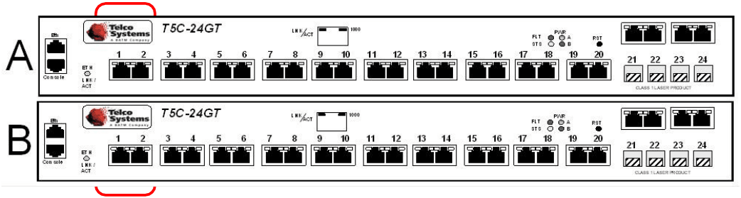 |
|
19. ☐ |
MPS A: Stop services after switch configuration. |
Change the startup information for tftp: |
|
20. ☐ |
Procedure complete. |
This procedure is complete. |