3 Customizing the Administration Client GUI
This chapter provides an overview of customizing the Oracle Communications Offline Mediation Controller Administration Client GUI.
DCNodeConfigGUI and Related Classes
The Administration Client GUI displays configuration panels for all nodes available in the system. Node developers must provide a class that displays configuration information specific to their node.
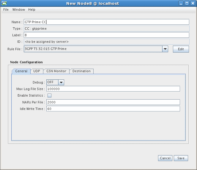
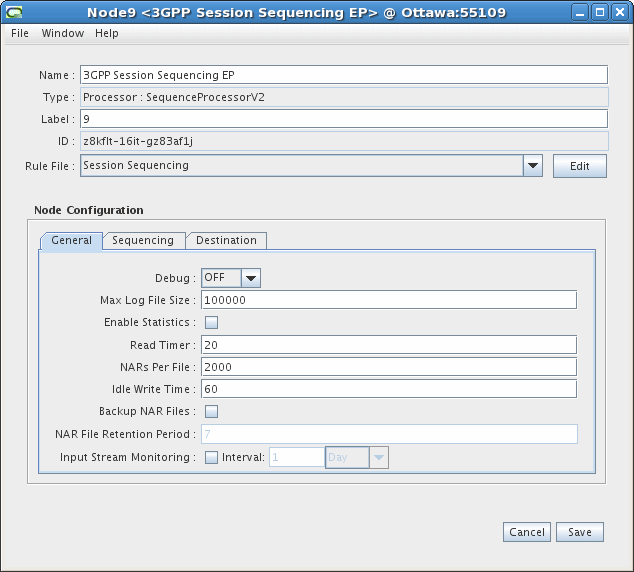
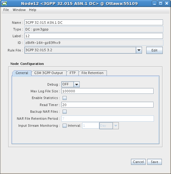
The base DCNodeConfigGUI classes provide the basic configuration tab panel, and the components on the General tab that are applicable for a particular node type. For CC and Processor nodes, a Destinations tab is provided which allows the user to select the nodes that will receive data from the node being configured.
The images below show the contents of the General tab for a Wireless CC, EP and DC node.
Offline Mediation Controller provides the basic panel layout, which includes the Node identification fields at the top and the configuration tab in the lower half of the screen.
New configuration GUI classes should be derived from the appropriate DCNodeConfigGUI class, and at least the following three methods should be overridden:
-
setDefaults() - provides appropriate default values for the configuration items being introduced. The defaultValue() method is used to set these individual values.
-
extendConfigGUI() - this is where any new tab panels are defined.
-
getNodeSpecificConfigData() - this method is responsible for getting the values from the text fields (or other components) and setting them in the DCNodeConfigData (nodeData) object, which will contain all of the valid configuration information for the node.
The allFieldsValid() method is called when the user selects the “Save" button. The default implementation always returns true. If any input verification is desired, that checking should be performed here.
The DCNodeConfigGUI base class provides some methods for creating basic components and panels:
-
makeTextField() and makeNumericTextField() create JTextField objects with the supplied parameters.
-
makeNumericTextField() provides simple input verification to ensure that the user has entered a numeric value. A minimum and maximum value can also be specified. If a minimum and maximum value are specified, these values will be enforced. If the user enters a value below the minimum, the minimum value will be displayed, conversely, if the user enters a value above the maximum, the maximum value will be displayed.
-
makePanel() accepts a Vector of labels and a Vector of components, and creates a JPanel that contains those items in the order in which they appear in the Vector. The addPanel() method then adds the panel to the tabbed pane in the GUI.
DCNodeConfigGUI Class Hierarchy
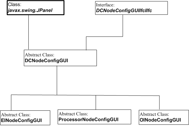
Figure 3-4 shows the DCNodeConfigGUI class hierarchy.
Figure 3-4 DCNodeConfigGUI Class Hierarchy

Description of "Figure 3-4 DCNodeConfigGUI Class Hierarchy"
Node Template Definitions and Groups
Rules files are the NPL files that will be used by the node (more specifically by the NPLFieldProcessor). These files are stored in the Offline Mediation Controller installation area in the “rules" sub-directory in a directory structure based on the node's major and minor type.
Node template files are used by the system to determine what nodes are available and how to display those nodes in the GUI tree view and Node Creation Wizard. These files are stored in the “config/template" directory.
There are two files the system uses to describe what a node is. The first, the nodeTemplateDef.xml file, defines the name of the node and other properties, such as the NPL files and the node class. The second file, nodeGroupDef.xml, defines the hierarchy of the nodes in the GUI. The system files cannot be modified but can be extended by creating a customized version in the OMC_Home/customization directory.
The nodeTemplateDef.xml File
The nodeTemplateDef.xml file defines node template elements. Each node template defines a single node in the system. For example, the following defines an Aggregation Processor node called Sample Node 001 with one NPL file.
<nodetemplate id="Access#AP#Testing001">
    <name>Sample Node 001</name>
    <property name="Solution">access</property>
    <rule id="aggr_csg_radius_correlation.npl">
        <name>Sample node correlation</name>
        <nplfile>sample_node_correlation.npl</nplfile>
    </rule>
    <nodeclass>com.nt.udc.aggregator.AggregatorNode</nodeclass>
</nodetemplate>
There are a large number of nodes already defined by the system nodeTemplateDef.xml file. This can be found in OMC_Home/config/nodeTemplateDefs. These definitions should never be changed, but they can be extended by adding new NPL files in the customized nodeTemplateDef.xml file. For example, if Sample Node 001 was defined in the system node templates and it was to be extended with a second NPL file called “sample_node_test.npl", the nodeTemplateDef.xml file in the customization directory would appear as follows:
<?xml version="1.0"?>
<nodetemplateset version="1.0">
    <nodetemplate id="Access#AP#Testing001">
        <rule id="sample_node_test.npl">
<name>Sample Node Test</name>
            <nplfile>sample_node_test.npl</nplfile>
        </rule>
    </nodetemplate>
</nodetemplateset>
Ensure you place the customized nodeTemplateDef.xml in OMC_Home/customization/nodeTemplateDefs. It can contain any number of node templates, that either add NPL files to existing system templates or define new nodes. Each rule element defines a single NPL file for the node. The id attribute of the rule should be a unique identifier for that NPL file. In general, the filename is used, although this does not have to be the case. Notice that the NPL files do not have any path specified. The system searches for the NPL files in the following manner:
-
Construct the abstract location of the NPL file as follows:
<MarketSegment>/<BasicNodeType>/<NodeSpec>/<Filename>
-
Search in OMC_Home/customization.
-
If you do not find the file, search in OMC_Home/rules.
The <MarketSegment> is defined by the first token of the nodeTemplate ID attribute (tokens are separated by a #).
In the example given above, the market segment is “Access". If the node ID was “Wireless#EP#FileEnhancer", the market segment would be “Wireless".
The <BasicNodeType> and <NodeSpec> can be determined by editing a node of that type in the GUI. The “type" field will give the both the <BasicNodeType> and <NodeSpec> separated by a colon.
In the previous example, the type field would display “Processor : Aggregator". So the location of the system defined NPL file for this node would be:
OMC_Home/rules/Access/Processor/Aggregator/sample_node_test.npl
If it were customized in sample_node_customized.npl, the location would be:
OMC_Home/customization/Access/Processor/Aggregator/sample_node_test.npl
Node templates have two other properties defined in the XML, a Solution property and a node class. The node class is the actual Java type that is instantiated by the system when creating a node of this type. The Solution property is the market segment used in licensing. Each node must have a valid Solution. If you are creating a new node template, the Solution should be set to CartridgeKit.
Only rule files listed in the node template definition will be shown in the GUI. Therefore to add a new NPL file, you must copy it into the appropriate directory and add it to the node template definition.
The nodeGroupDef.xml File
The nodeGroupDef.xml file defines the hierarchy of nodes for the GUI to use in its tree view and the Node Creation Wizard. This file has two elements in it, the nodetemplategroup and the nodetemplate. The nodetemplategroup elements define the groupings and the nodetemplate elements define the leaf nodes. Each nodetemplategroup contains a name and either a list nodetemplategroups or a list of nodetemplates. Each nodetemplate is an empty element and has an ID that references an existing nodetemplate in the nodeTemplateDef.xml file. The nodeGroupDef.xml file can be extended by adding various nodetemplategroups and nodetemplates to a nodeGroupDef.xml file in the customization directory.
For example, if the following was the system nodeGroupDef.xml file:
<?xml version="1.0" standalone="yes"?>
<nodetemplategroup>
    <name>root</name>
    <nodetemplategroup>
        <name>Wireless</name>
        <nodetemplategroup>
            <name>Collection Cartridge (CC)</name>
            <nodetemplate id="Access#AP#SessionCorrelation"/>
            <nodetemplate id="Access#AP#CsgRadiusCorrelation"/>
        </nodetemplategroup>
    </nodetemplategroup>
</nodetemplategroup>
This could be extended by creating the following nodeGroupDef.xml file in the customization directory.
<?xml version="1.0" standalone="yes"?>

<nodetemplategroup>
    <name>root</name>
    <nodetemplategroup>
        <name>Wireless</name>
        <nodetemplategroup>
            <name>Collection Cartridge (CC)</name>
            <nodetemplate id="Access#AP#Test001"/>
        </nodetemplategroup>
    </nodetemplategroup>
</nodetemplategroup>
Creating a node and rule file
To create a customized node, you must access the node type you want to use as a template and create a new rule file. To access the node type templates, go to the Cartridge Kit market segment in the Offline Mediation Controller Administration GUI.
Use the following procedure to create a customized node with a new NPL rule file.
Select the node type template to build on
-
In the Administration GUI, go to the Nodes on Mediation Host section and click the New button.
-
Select the Cartridge Kit market segment and click Next.
-
Select the Node Type and click Next.
-
Select a node and click Finish.
The node configuration window appears.
Create and save the new NPL rule file
-
In the node configuration window, ensure “New" is selected in the Rule File drop-down list and then click the Edit button.
-
Use the template that appears in the NPL Editor window to create your new NPL rule file.
-
Select File and Save to open the Save As... dialog box. Type in the name of the Display Name. Type in the Rule File Name and ensure the file name ends with “.npl".
Click Save.
-
Exit the NPL Editor by selecting File>Exit.
-
Ensure the new rule file is in the list.
-
Configure the information required in the various window tabs.
-
Click Save.


