2 About Configuring Nodes and Node Chains
You configure node chains in Oracle Communications Offline Mediation Controller by using the Administration Client application.
Topics in this document:
About Creating Node Chains
Before you can configure node chains, you need to install and configure the Offline Mediation Controller components.
-
Start the Offline Mediation Controller components:
-
Oracle Universal Directory
-
One or more node managers
-
The administration server
-
Administration Client
For information, see "Starting and Stopping Offline Mediation Controller" in Offline Mediation Controller System Administrator's Guide.
-
-
In Administration Client, create mediation hosts for each instance of a node manager. To create a mediation host, you assign the host name and port number of a node manager. After a mediation host is created, you can create nodes and node chains.
-
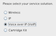
When you create a new node on the mediation host, Administration Client presents a series of choices that enable you to select a node for your solution. First, you select the solution type:
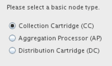
Then, you select the node type:
Depending on the solution type and node type, you then select a node specialization:
Figure 2-3 Selecting a Node Specialization
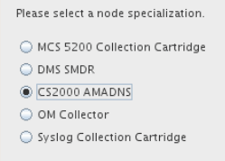
Description of "Figure 2-3 Selecting a Node Specialization" -
Each node requires configuration and might require you to edit the rule file. All configurations and editing of rule files are performed in Administration Client.
-
When all nodes are created and configured, create a node chain by doing the following:
-
Create the CC, EP, AP, and DC nodes as necessary.
-
Specify the order of the nodes in the node chain by dragging and dropping connection lines from the output of one node to the input of another node.
-
In the CC node, set up a method for Offline Mediation Controller to receive input from an external system.
-
In the DC node, set up a destination for Offline Mediation Controller to send data to.
-
-
After the nodes are configured and connected, start the node chain.
About Node Configuration
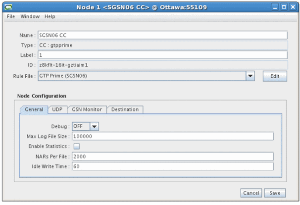
To configure nodes in Administration Client, choose the type of node that you want and then edit the configuration in a dialog box. Each node can have different configuration options depending on the node functionality. For example, CC nodes can include file input configuration, and DC nodes have no configuration for destination nodes.
Figure 2-4 shows a node configuration dialog box.
In this figure:
-
All nodes include an option to select a rule file and edit it.
-
All nodes include a General tab, which specifies administration parameters, such as log file configuration. Each type of node can have different requirements, so the options vary. For example, some nodes raise an alarm if no input is received in a specified amount of time.
-
CC, EP, and AP nodes include a Destination tab. This tab lists the nodes that the node connects to. You use the Destination tab to specify the type of routing to use, such as multicast or round robin. See "About Distributed Node Chains".
-
All other tabs in a node configuration depend on the node functionality. For example, in Figure 2-4, the node needs to use User Datagram Protocol (UDP) to get data, so the UDP tab configures the UDP connection.
For information about the options in each dialog box tab, see Offline Mediation Controller Online Help.
About Configuring EC and AP Nodes
In addition to general and destination configurations, EC nodes and AP nodes typically include node-specific configuration parameters. For example:
-
The duplicate check EP node uses a De-Duplication tab to configure options such as where to store the files that hold duplicate records, the number of records per file, and so on.
-
The record recycling EP node uses a Database Info tab to configure the connection information required to send records to a database.
-
The session aggregation AP node uses an Aggregator tab to specify how often to send aggregated records to the next node in the node chain.
About Editing Rule Files
You edit rule files when you configure nodes in Administration Client. You open the rule file, edit it, and perform a test compilation. If compilation fails, you can edit it again. When compilation succeeds, save the file.
Rule files define the functionality that a node carries out. For example:
-
The rule file for a CC node contains that mapping and normalizing rules that translate incoming data into a NAR.
-
The rule for a DC node contains that rules that transform a NAR into the output needed by the target system.
-
The rule file for an EP node contains functions that manipulate data.
In many cases, a node has a pre-configured rule file that does not need editing. In some cases, a node can include multiple rule files that you can choose from, such as to specify a different output. In some cases, you need to select a rule file and edit it.
Editing a rule file can be as simple as providing a value in a name-value pair. For example, the following entry in a rule file specifies the field to use when checking for duplicate records:
DUP_CHECK_KEYS "calling_number session_id seq_no";
You can also use Java hooks to implement more complex mappings and configurations. For example, this Java hook implements a JDBC connection:
Config {
JDBCDriver "oracle.jdbc.driver.OracleDriver";
JDBCUrl "jdbc:oracle:thin:@%DBHOST%:%DBPORT%:%DBSID%";
}
Java hooks are provided by each cartridge. For example, the Oracle CDR Format Cartridge includes many Java hooks to validate input.
For more information about using Java hooks with NPL, see "Java hooks" in Offline Mediation Controller Cartridge Development Kit NPL Reference Guide.
About Node Routing
You can use various types of routing in a node chain to process NARs in different ways and implement load balancing. You can use:
-
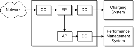
Multicast routing to branch a node chain and send all of the NAR files to both branches. Figure 2-5 shows a node chain with one input and two outputs. In this configuration, the EP node sends all of the NAR files to two different nodes: one for output to a charging system, and one to an aggregation processor that sends the NARs to a performance management system.
Figure 2-5 Node Chain With Multicast Routing
Description of "Figure 2-5 Node Chain With Multicast Routing" -
Directed routing to send NAR files to different branches. For example, you can branch a node chain based on the value of a field in the NAR. Figure 2-6 shows a node chain that implements an additional aggregation step for only some of the NAR files.
You can improve performance by creating multiple instances of the same processing node. You can then route NAR files to different instances to process the files in parallel. Figure 2-7 shows a CC node configured to send NAR files to one of three different EP nodes.
Figure 2-7 Distributing NAR Files to Multiple Instances of the Same EP Node

Description of "Figure 2-7 Distributing NAR Files to Multiple Instances of the Same EP Node"
To send NAR files to different nodes as shown in Figure 2-7, you can use:
-
Round robin routing, which rotates to which node the NAR file is sent.
-
Modulus routing, which sends the NAR file to a node based on a field value in the NAR.
See Offline Mediation Controller Online Help for information about configuring NAR file routing.
You configure NAR routing in two places:
-
In the Destination tab when you configure the node. For example, you can choose multicast or round robin routing. Figure 2-8 shows a node configured to use multicast routing for one destination node, but no routing for the other nodes.
Figure 2-8 Routing Configured in the Destination Tab

Description of "Figure 2-8 Routing Configured in the Destination Tab" -
When you drag and drop a connection from one node to another. If routing is enabled for the destination node, you enter the routing method. For example, to configure distributed routing, you specify the conditions that enable the NAR file to be sent to the destination node.
About Distributed Node Chains
You can manage performance by configuring node chains on multiple mediation hosts.
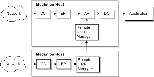
Figure 2-9 shows a node chain that runs on two mediation hosts. This node chain receives input from two devices, but outputs to one application. The Remote Data Manager sends the output NAR of an EP node on one mediation host to the input of the AP node in the other mediation host.
Figure 2-9 Running a Node Chain on Two Mediation Hosts
Description of "Figure 2-9 Running a Node Chain on Two Mediation Hosts"
You can run multiple instances of Offline Mediation Controller by running multiple pairs of administration server primary and backup servers. If you do, you can send NAR files from the DC node in one instance of Offline Mediation Controller to the CC node in another instance. Figure 2-10 shows node chains connected across administration servers.
Figure 2-10 Connecting Node Chains on Different Administration Servers

Description of "Figure 2-10 Connecting Node Chains on Different Administration Servers"
