20 Working with Capabilities Cartridges (Cloud Native Only)
This chapter describes the guidelines, limitations and restrictions for generating Design Studio workspace content as a capabilities cartridge.
About Capabilities Cartridges
A capabilities cartridge is a packaging concept. It is not a new cartridge type but instead relates to the way a set of OSM cartridge content is packaged for delivery into the dynamic design process.
About Dynamic Cartridge Assembly (Cloud Native Only)in OSM Concepts provides an overview of the Dynamic Cartridge Assembly feature. You need to understand this feature to understand how a capabilities cartridge fits within OSM.
About OSM Participant provides an overview of the steps that you need to take in both Solution Designer, and OSM to use Capabilities Cartridges. You need to understand the way this exchange functions to use a capabilities cartridge.
You should have a good working knowledge about writing OSM orchestration cartridges as context for the information in this chapter.
About Capabilities Cartridges Restrictions
- You can use only TMF cartridges to generate a capabilities cartridge CPAR file.
- It must host a TMF 622 specification.TMF 641 is not yet supported for capabilities cartridge development.
- The OSM target server version in Design Studio must be 8.0 or later.
- Only a single capabilities cartridge can be delivered to dynamic design. Multiple versions of the capabilities cartridge (as identified by the Solution name) are allowed. For example, multiple COM solutions are not allowed, but multiple versions of a single COM solution is possible.
User Workflow in Design Studio
For background information about user journeys, refer to About Dynamic Cartridge Assembly (Cloud Native Only) in OSM Concepts.
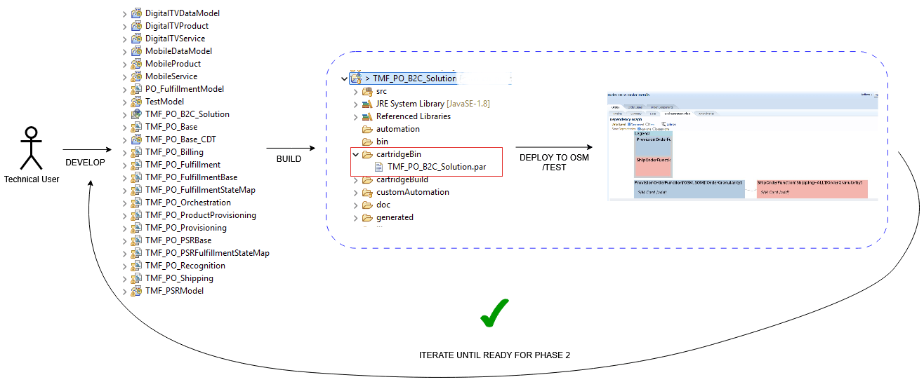
The following image shows the traditional design journey for developing and deploying cartridges using Design Studio and OSM.
Figure 20-2 Phase 1 of Dynamic Design Journey
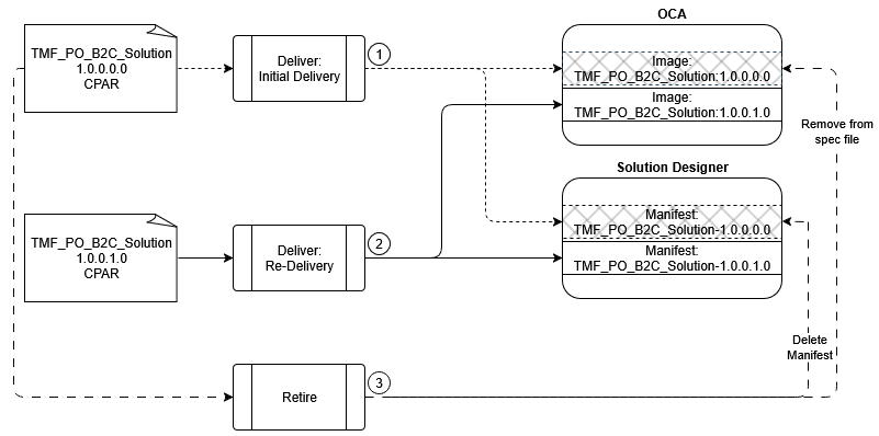
Capabilities Cartridge Lifecycle
All lifecycle stages must be managed in a coordinated manner between the OSM Cartridge Assembler (OCA) microservice and Solution Designer. Any changes or updates that you make in one application must also be reflected through a corresponding update in the other application. This synchronization ensures that both systems remain aligned, reducing the risk of inconsistencies and operational errors.
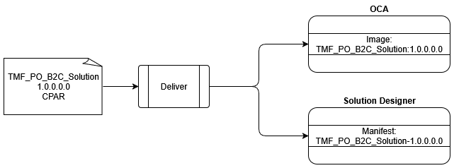
Creating and Delivering the CPAR
- A CPAR archive that is used to create an image that is loaded into the OSM Cartridge Assembler Microservice. For more information about this, refer to Container Images in the OSM Cloud Native Deployment Guide.
- A manifest file that is extracted from the archive to import into Solution Designer.
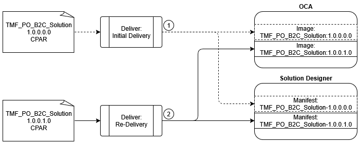
Updating and Re-Delivering the Capabilities Cartridge
- Only OCA, such as an XQuery change
- Only SCD, such as the OSM entity descriptions
- Both applications, such as adding, removing or updating the OSM capabilities. For example, introducing new or changed fulfillment patterns, fulfillment functions or fulfillment systems
Regardless of its type, you need to exclusively re-deliver any change you make through Design Studio. You need to ensure that all Design Studio content is being maintained under source control to ensure deliverable artifacts can be reliably and repeatedly generated. This approach promotes consistency, traceability, and reproducibility in your deployment process.
To further enhance traceability, Oracle strongly recommends that when you are making changes to the capabilities cartridge produced by Design Studio, you also change the version.
Figure 20-4 Updating and Re-Delivering the CPAR
Retiring a Capabilities Cartridge
Note:
Solution Designer does not support retirement of a manifest once it has been released to production.Capabilities Cartridge Content
This section describes some limitations and conventions when packaging content as a capabilities cartridge.
Design Studio Workspace
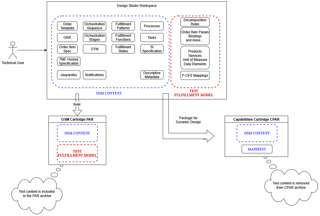
A Design Studio workspace can be organized in such a way that it can support both a traditional build (PAR) or capabilities cartridge generation (CPAR). While PAR files can be deployed to OSM and take effect immediately (allowing OSM to process orders), a CPAR file needs to be delivered differently. A CPAR file cannot process orders - it needs to be part of the dynamic cartridge process first.
In order to be compatible with the dynamic cartridge assembly process that takes place in the OCA microservice, the capabilities cartridge must adhere to the restrictions and conventions outlined in this chapter. OSM delivers a reference sample inside the OSM SDK that can be built as a capabilities cartridge. It aligns to the correct design studio workspace setup, and follows the guidelines outlined here.
Capabilities Cartridge Conventions
Fulfillment Model
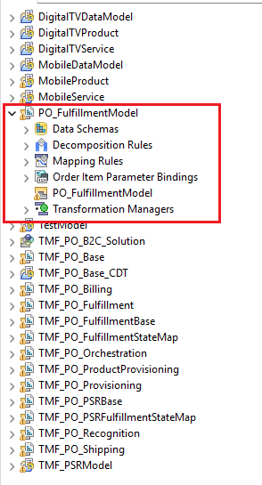
A single component cartridge must hold the fulfillment model. In the reference sample, this is PO_FulfillmentModel.
Note:
This does not apply to items in the resources (such as XQueries) directory.Order Recognition Rule
The cartridge version changes every time you publish from Solution Designer. Therefore, you need to set the Target Order Version as default in the Order Recognition Rule.
XML Catalogs
Any XML catalog that references the resources held in the fulfillment model cartridge (PO_FulfillmentModel), needs to use default in the re-write string instead of a version number as this will be updated with each publish from Solution Designer.
<!-- Support ParameterBinding -->

<rewriteURI uriStartString="http://oracle.communications.orchestration.com/tmf-api/productOrderingManagement/%{TMF622_VERSION}/productOrder/parameterBinding" rewritePrefix="osmmodel:///PO_FulfillmentModel/default/resources/parameterBinding"/>
Automation Concurrency Map
<targetPlugins>
  <cartridgeNamespace>TMF_PO_B2C_Solution</cartridgeNamespace>
  <pluginSelector>.[cartridgeNamespace="TMF_PO_B2C_Solution"][implement/script/url="http://oracle.communications.orchestration.com/tmf-api/productOrderingManagement/%{TMF622_VERSION}/productOrder/provisioning/componentInteraction/4.1.0.1.0/serviceOrderStateChangeReceiver.xquery"]</pluginSelector>
</targetPlugins>
Relationship Types
The Relationship Type entity is not configurable in Solution Designer. However you can use the associations Primary and Auxiliary in the product to service relationship.
These entities are still defined in the capabilities cartridge instead of being test content, because of the action configuration these entities carry. Refer to Mapping Rules for more details.
- You must create a relationship called Primary.
- You must create a relationship called Auxiliary. Design Studio will enforce this when the capabilities cartridge is generated.
- You must not create any additional relationship types.
Provider Function
If you use OTM, the provider function must have the two relationship types defined - Primary and Auxiliary, with Primary set as the default.
Description Fields
While description fields on various objects in Design Studio are optional, it is strongly recommended that you populate these fields with care. The description is a means of communicating information from the technical user in Design Studio to the business modeler in Solution Designer.
The descriptions should capture meaningful details for the following entities in Design Studio:
- All order components (functions, systems, granularities)
- Fulfillment patterns
You can provide an overall description to summarize the entire cartridge as part of the Capabilities Cartridge wizard. All of these descriptions will be visible to the business modeler in Solution Designer in order to guide them on the nature of these entities and any other relevant aspects, such as functional assumptions made by the technical user.
Fulfillment Pattern Property on the Order Item Specification
Product definitions are pruned from the capabilities cartridge during generation. Due to this, Design Studio cannot populate the productSpecMapping.xml file with mapping details. Prior to OSM 7.5.0, this file was used to determine the correct fulfillment pattern for the inbound line item.
Note:
See the "How to Simplify the Fulfillment Pattern Property on an OSM Order Item Specification (Doc ID 3000040.1)" KM article on My Oracle Support for more information on simplifying the fulfillment pattern property on an OSM Order Item Specification.In the capabilities cartridge, you need to populate the fulfillment pattern property with the incoming product specification name instead of the fulfillment pattern name. This simplified mapping defined in the capabilities cartridge will be coupled with the compatible OSM metadata during dynamic assembly so that OSM can resolve the correct pattern to use.
Transformed Order Item Properties
You need to create the following properties on the transformed order item so that they can be populated by the cartridge assembly process. These values are needed by the automation plugin constructing the TMF 641 service order.
- ServiceSpecificationId
- ServiceSpecificationName
Order Component Organization
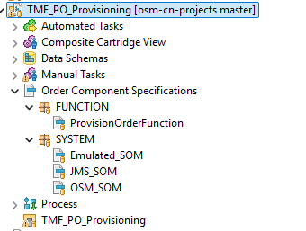
OSM uses cartridge boundaries to create the correct function to system hierarchy. This is used to construct a graphical fulfillment pattern display in Solution Designer. A functional cartridge must therefore contain order components representing the function and all applicable fulfillment systems.
Configurability Limitations
In the dynamic design journey, Solution Designer has ownership for some entity definitions but it does not provide the same level of OSM specific configurability which can be seen in Design Studio. This is necessary to provide a simpler and more streamlined experience for the modeler, but the cartridge developer needs to be aware of the impact this may have on the fulfillment logic in the capabilities cartridge.
General Restrictions
- You must use a single cartridge to hold the fulfillment model.
- You must use three stage orchestration which includes decomposition to function, to system, and to granularity.
- You cannot use structured data elements on catalog entities (product or service entities).
Mapping Rules
The limitations in this area are:
- The mapping options for individual attribute mappings support copy value, value map and unit of measure. There is no equivalent for advanced mapping in Solution Designer.
- You cannot map order item properties (from source to target). Refer to Transformed Order Item Properties for a detailed explanation.
- The primary relationship is used to drive order item selection. This is set during dynamic assembly and cannot be changed in Design Studio or Solution Designer
- You cannot configure action codes directly. These come from the action codes defined in the capabilities cartridge and cannot be restricted in Design Studio or Solution Designer
- You cannot configure action mappings directly. These are driven from the relationship action map. This is set during dynamic assembly and cannot be changed, however the relationship type and its action map can be defined in Design Studio
- You cannot configure fulfillment state filters directly. These come from the order component that uses the provider function and cannot be restricted in Design Studio or Solution Designer
- All mappings support bi-directional mapping. This is set during dynamic assembly and cannot be changed in Design Studio or Solution Designer
Transformation Sequence
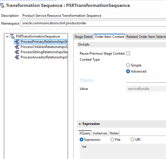
The transformation sequence editor allows you to define the order item context for the Primary Relationship stage. Design Studio enforces this configuration even though the context can be driven from similar configuration in the mapping rule.
You need to provide the configuration that Design Studio needs to generate a capabilities cartridge successfully and without any build errors. At the same time you need to ensure that the configuration you provide does not conflict with what is applied during dynamic cartridge assembly.
In the editor, select Advanced as the context type, and for the expression use 'na'. The following image shows sample Tranformation Sequence configuration.
Decomposition and Routing Rules
Routing rules in Solution Designer get translated into decomposition rules in OSM. The following limitations apply to routing rule configuration:
- There is no means to limit the applicability of a routing rule to a fulfillment pattern or a set of fulfillment patterns.
- The conditions on a routing rule apply equally to the rules controlling the second and third stage of decomposition. You cannot configure a condition that applies to the function stage to the system stage differently than it applies to the system stage to granularity stage.
- Cartridge assembly enforces that only a single routing rule can reference a fulfillment function. You cannot have two rules that both target the same function.
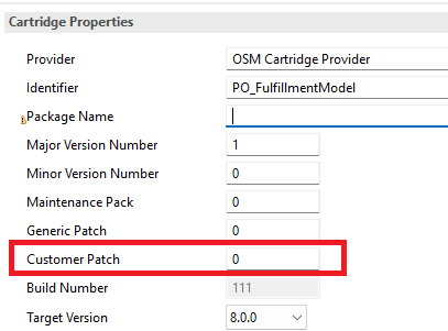
Cartridge Versioning
Note:
Any changes you make to the customer patch value for the fulfillment model and solution cartridges in the Design Studio workspace will not be preserved.Figure 20-8 Customer Patch Value in Cartridge Versioning
DataTypes for Product and Service Attributes
- string
- boolean
- int
- long
Solution Designer supports more data types (including structured data) but these are not permitted by dynamic cartridge assembly. You need to ensure that the cartridge logic relies only on the supported data types so that your orders process successfully.
Transformed Order Item Properties
You can define a set of general properties in the Order Item Specification editor in Design Studio. These values are populated based on the mappings on the Product (PS) - Service (CFS) mapping and not by any configuration applied on the Order Item Specification editor.
Since Solution Designer does not expose OSM specific configurability for PS-CFS mappings, you cannot map the order item properties.
For an automation plugin to correctly generate a TMF 641 order, it needs access to data about the CFS that is not defined as a service characteristic.
To bridge this gap, dynamic assembly provides the following property mappings for primary PS-CFS relationships:
- ServiceSpecificationName: This should be created as an order item property. It will then be populated automatically from the CFS ID defined in Solution Designer.
- ServiceSpecificationId : This should be created as an order item property. It will then be populated automatically from the CFS Name defined in Solution Designer.
- The property that is declared as the Order Item ID Property will be populated with a random UUID.
- The property that is declared as the Fulfillment Pattern Mapping Property will be copied from the source fulfillment pattern and needs to be populated for successful cartridge deployment.
Capabilities Cartridge Test Scaffolding
Test data is created in Design Studio and is required during the traditional design journey, outlined in User Workflow in Design Studio when the re-usable OSM capabilities are being validated through the traditional build and deploy cycle.
Fulfillment Model
- PSR (Product, Service, Resource) Entities
- Products
- Services
- Data Elements
- Unit of Measure Converters
- OSM Entities
- Mapping Rules
- Decomposition Rules
OSM Enrichment Data
- Order Item Parameter Bindings
- Transformation Manager
- Product to Fulfillment Pattern Mappings
Figure 20-9 Test Data During Design Journeys
Cartridge Guidelines for Test Data
The cartridges must cleanly separate the re-usable entities (the capabilities cartridge) from the test data. The test data is defined across different cartridges depending on the type of data it holds such as OSM entity, OSM enrichment or PSR (Product, Service, Resource).
OSM Test Content
You must define OSM entities and OSM enrichment data in a single OSM cartridge. This cartridge will be specified as the Fulfillment Model Cartridge during the generation of the capabilities cartridge.
Figure 20-10 Sample Fulfillment Model Cartridge
Conceptual Model Test Content
Note:
For more information about Conceptual Models, refer to Working with Conceptual Models.The reference sample workspace contains Product and Service definitions for Mobile and Digital TV domains and the PO_FulfillmentModel acts as the container cartridge.
Additionally, unit of measure converters which are available in Solution Designer and conceptual fulfillment patterns which are only required in Design Studio, are defined in model projects and are contained in PO_FulfillmentModel.
Reusable Conceptual Model Content
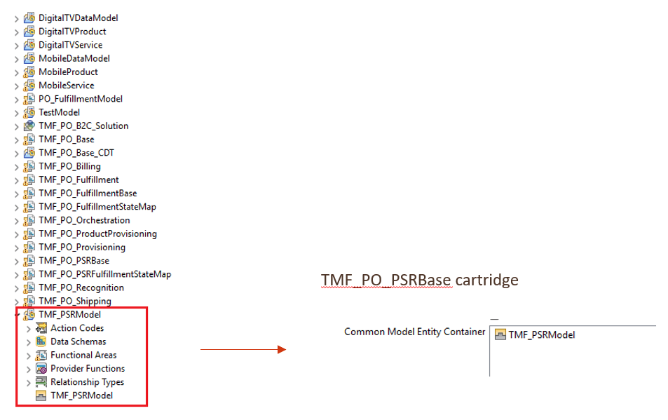
When order transformation is used in the fulfillment logic, then you must define several other conceptual entities. They are considered reusable content from a dynamic design perspective.
You must preserve these entities when building the cartridge. Therefore a separate OSM cartridge must act as the container for the associated metadata. In the reference sample workspace, the TMF_PO_PSRBase takes on this role.
Capabilities Cartridge Build
This section provides an overview of the process and the output that you get when building the capabilities cartridge.
Using the Capabilities Cartridge Wizard
When you are using the Capabilities Cartridge Wizard, you can select a set of order item properties for exposure in Solution Designer. You should restrict the properties selected to what needs to be exposed to correctly configure routing rules (OSM decomposition rules).
Properties that are created for the cartridge fulfillment logic do not need to be exposed to the business modeler and therefore should not be selected. Additionally, you must not select properties that use date, time or datetime as they are not supported by dynamic assembly.
About the CPAR File
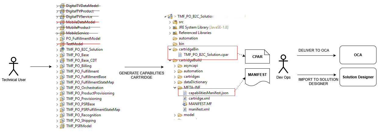
When you are using the Capabilities Cartridge Wizard, you need to designate a cartridge in the workspace as the fulfillment model cartridge. This will be the cartridge that contains the test data.
Based on the inputs you provide to the wizard, Design Studio strips the test content before packaging the CPAR archive. This stripped content includes everything in the /model directory.
The cartridge itself is still packaged in the CPAR and retains the following:
- Cartridge dependencies and model variables
- Everything in the /resources directory
- xmlCatalogs
Cartridge developers need to note that the pruning of test data is not selective, and any non-test data that gets defined in the fulfillment model will be lost when the CPAR is generated.
Capabilities Manifest Details
The capabilities manifest consists of 2 types of data:
- Entities that are exposed in Solution Designer and can be referenced when configuring a fulfillment model
- Metadata that is used internally by the dynamic assembly process
None of this data should be manipulated by a human user.
Table 20-1 Exposed Capabilities in Solution Designer
| Field | Description |
|---|---|
| description | Textual summary of the capabilities offered in the cartridge, to be used by modelers in Solution Designer. Usage summary entered in the Capabilities Cartridge Wizard. |
| orderItemSpecification/property | List of order item specification properties selected in the Capabilities Cartridge Wizard. These are available for use in routing rule conditions in Solution Designer. |
| orderComponents | Order components are grouped according to their
classification into functions, systems, or granularities.The
Product configuration in each orchestration stage drives
the classification (only leaf components).
|
| fulfillmentMode | The standard fulfillment mode for TMF orders - deliver. This is informational in Solution Designer. |
| fulfillmentPattern | List of fulfillment patterns and their orchestration plan details. Products are mapped to these patterns in Solution Designer. |
| component | List of order components that are part of the orchestration plan of a fulfillment pattern. These are used to build a graphical representation of the pattern in Solution Designer. |
| transition | List of transition dependencies for the order components in a fulfillment pattern. These are used to build a graphical representation of the pattern in Solution Designer. |
For more information, refer to Packaging and Deploying a Capabilities Cartridge in Design Studio Modeling OSM Orchestration.
