Understanding the Main Page - Full Operations User Type
The primary page for performing work is made up of four tabs, which are described in the following sections:
Understanding the Tasks Tab
The Tasks tab provides a listing of any events that you are assigned to. The general event details are listed in a row that expands to reveal available actions when selected.
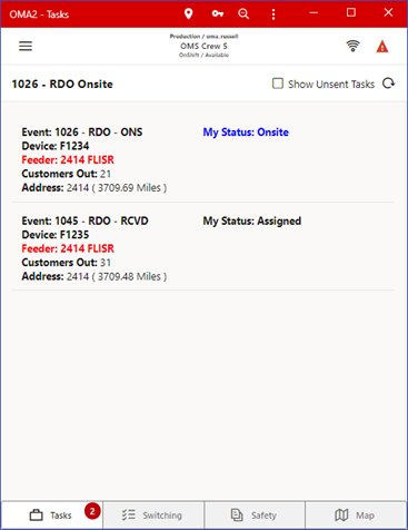
The Show Unsent Tasks check box will allow you to show or hide tasks that have been assigned to your crew but not sent to your device. This is possible if NMS has the Two-Step Crew Assignment rule enabled.
Tap on a task to display a list of relevant actions.
Depending on the state of your task (for example, Assigned, En Route, Onsite), you may have the following options.
• A Show in Map icon ( ), when tapped, will open the map panel and focus the map on the task.
), when tapped, will open the map panel and focus the map on the task.• A Get Directions icon ( ), when tapped, will open the devices native navigation app to assist you in driving to the task location.
), when tapped, will open the devices native navigation app to assist you in driving to the task location.• An En Route icon( ), when tapped, will flag that you are en route to the event.
), when tapped, will flag that you are en route to the event.• An On Site icon ( ), when tapped, will flag that you are on site for the event.
), when tapped, will flag that you are on site for the event.• An Assign or Suspend icon ( ), when tapped, will change your status back to Assigned or Suspended for the event.
), when tapped, will change your status back to Assigned or Suspended for the event.• A Reject Task icon ( ), when tapped, will remove the task from your list of Tasks.
), when tapped, will remove the task from your list of Tasks.• A Read icon ( ), when tapped, will transition the event to the Crew Read (CRD) state.
), when tapped, will transition the event to the Crew Read (CRD) state.• A Send to Crew icon ( ), when tapped, will send the event to your crew.
), when tapped, will send the event to your crew.• An Event Info icon ( ), when tapped, will open the Event Info page and allow you to review and update the event. See “Understanding the Event Details Page - Full Operations User Type” for more information.
), when tapped, will open the Event Info page and allow you to review and update the event. See “Understanding the Event Details Page - Full Operations User Type” for more information.• A Damage Reports icon ( ), when tapped, will open a new panel with a list of damage reports associated with the event and allow you to open them.
), when tapped, will open a new panel with a list of damage reports associated with the event and allow you to open them.• A Work Queue icon ( ), when tapped, will open Select Work Queues dialog box, which allows you to assign the task to the selected work queues. You may also enter an optional comment.
), when tapped, will open Select Work Queues dialog box, which allows you to assign the task to the selected work queues. You may also enter an optional comment.• A Real Outage icon ( ), when tapped, will confirm the probable outage as a real outage and will open the device in the model.
), when tapped, will confirm the probable outage as a real outage and will open the device in the model.• A Confirm Outages icon ( ), when tapped, will open a panel with a list of customers associated with the outage and allow you to mark them as confirmed service outages or confirmed secondary outages.
), when tapped, will open a panel with a list of customers associated with the outage and allow you to mark them as confirmed service outages or confirmed secondary outages.• A More selection icon () allows you to create a switching sheet as a copy of an existing template sheet identified by a Template ID (see “Understanding the Template ID Field”).
Note: The switching sheet copy options are configuration dependent and based on the templates saved by an Administration user.
Understanding the Switching Tab - Full Operations User Type
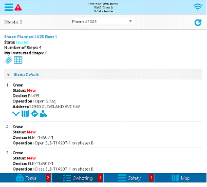
The Switching tab provides a drop-down list that allows you to select from any switching sheets that are assigned to the crew. The pane below the drop‑down list displays the switching sheet name, its state (New, Issued, instructed, and so on), and the number of instructed steps. The Switching tab also includes a number of sheets in the upper left-hand corner. This same number can be found on the Switching tab.
Buttons
• The Switch Sheet Report icon ( ), when tapped, will bring up the Switching Sheet Report Options panel, allowing you to select the content of the Switching Sheet report to generate and to initiate the report generation. After the server generates the report, it will be brought up in the device's native PDF file viewing application.
), when tapped, will bring up the Switching Sheet Report Options panel, allowing you to select the content of the Switching Sheet report to generate and to initiate the report generation. After the server generates the report, it will be brought up in the device's native PDF file viewing application.• The Attachments icon ( ), when tapped, will bring up the Switching Sheet Attachments panel. It will display any existing switching sheet attachments, which you may open and view with a device application. You also may add attachments using the following options.
), when tapped, will bring up the Switching Sheet Attachments panel. It will display any existing switching sheet attachments, which you may open and view with a device application. You also may add attachments using the following options.• A camera icon ( ), when tapped, will bring up the device camera application and allow you to take a photo and attach it to the switching sheet.
), when tapped, will bring up the device camera application and allow you to take a photo and attach it to the switching sheet.• A Search icon ( ), when tapped, will bring up a file selection panel and allow you to attach a file.
), when tapped, will bring up a file selection panel and allow you to attach a file.• The Complete Switching Sheet icon ( ) will appear if you have permission to complete switching sheets and all the steps of the switching sheet are in a terminal state.
) will appear if you have permission to complete switching sheets and all the steps of the switching sheet are in a terminal state.Steps
The steps are grouped within a block step that can be expanded or collapsed by clicking the icons displayed to the far left of the block row’s name.
When shown, each step will have a step number to the far left along with the following fields:
• The Crew field displays all of the crews that are currently assigned to this step.
• The Status field displays the current state of the step. This includes, but is not limited to New, Instructed, and Completed. For a full list of step states, see “Switching Sheet States”.
• The Device field displays the device alias referenced in the step.
• The Operation displays the description of the switching action. When the switching action is associated to a safety document, then the safety document type and number will be displayed in this field after the switching description.
• The Address displays the address of the device referenced in this step. This field is only visible when the switching step card is selected. To the right of the address is an address edit icon (), that, when tapped, will bring up an Enter or Change Step Address panel that allows you to change the address. This icon will only be visible if your crew has been assigned to the step.
), that, when tapped, will bring up an Enter or Change Step Address panel that allows you to change the address. This icon will only be visible if your crew has been assigned to the step.• The External ID displays the external id (if one exists) of the tag referenced in the step. To the right of the External ID field, is an edit icon (), that, when tapped, will bring up an Enter or Change Step External ID panel that allows you to edit the ID. The icon is visible only if your crew has been assigned to the step. You cannot edit the ID if the step is completed.
), that, when tapped, will bring up an Enter or Change Step External ID panel that allows you to edit the ID. The icon is visible only if your crew has been assigned to the step. You cannot edit the ID if the step is completed.When the switching step card is selected, a set of available icons will be shown for that step. Not all the icons will be shown at the same time and some will be dependent on the state of the step. Below is the list of available icons.
• The Show/Hide Child Steps icons (, ) expand or collapse additional switching step cards pertaining to an aggregate step. These icons will only be shown when an aggregate step is highlighted. Note: The child steps cannot be individually selected, instructed or executed and are only there for display purposes.
• The map icon (), when tapped will take you to the OMA map panel and center the map on the step’s location.
), when tapped will take you to the OMA map panel and center the map on the step’s location.• The navigation icon (), when tapped will open the device's native navigation application to assist you in driving to the switching step’s location.
), when tapped will open the device's native navigation application to assist you in driving to the switching step’s location.• Users with permission to self-instruct switching steps will see a self-assign icon () for steps that have not been instructed or assigned to a different crew. When selected, it will instruct the step.
) for steps that have not been instructed or assigned to a different crew. When selected, it will instruct the step.• If a step is in the New or Uninstructed state, a Ready for Instruct icon ( ) will appear and allow the OMA user to notify the NMS operator they are ready to be instructed. This will appear on the NMS Switching Step row. If the step already has been marked as Ready for Instruct, a Not Ready for Instruct icon (
 ) will appear and allow the OMA user to clear a previous notification of ready for instruct.
) will appear and allow the OMA user to notify the NMS operator they are ready to be instructed. This will appear on the NMS Switching Step row. If the step already has been marked as Ready for Instruct, a Not Ready for Instruct icon () will appear and allow the OMA user to clear a previous notification of ready for instruct.• If the step has been instructed to be complete, three extra icons will be shown:
• A Step Complete icon ( ).
).
).• A Step Abort icon ( ).
).
).• A Step Fail icon ( ).
).
).• For steps that have been instructed, you will see an un-instruct icon ( ) that allows you to un-instruct the step.
) that allows you to un-instruct the step.When any of the step state transition icons are tapped, an Enter or Change Step Information panel will appear and allow you to enter updated step Details, Date/Time or Comments. After clicking the save icon ( ) on the Enter or Change Step Information panel, the server will be notified and if applicable, the step’s operation will be applied to the NMS model. The step data entered and the state of the step will be broadcast to any NMS users that may be monitoring the switching steps at that time.
) on the Enter or Change Step Information panel, the server will be notified and if applicable, the step’s operation will be applied to the NMS model. The step data entered and the state of the step will be broadcast to any NMS users that may be monitoring the switching steps at that time.Understanding the Safety Tab - Full Operations User Type
The Safety tab displays a list of Safety documents assigned to your crew. Each assigned Safety document, when selected, will provide options specific to the type and state of the Safety document.
You have the option to view the Safety document and execute the steps to place it. You may also unissue the Safety document or release it.
• The Unissue icon ( ) is used to place an issued safety document into an Unissued state to be updated.
) is used to place an issued safety document into an Unissued state to be updated.• The Release icon ( ) releases an issued safety document so it may be assigned to another crew.
) releases an issued safety document so it may be assigned to another crew. Understanding the Map Tab - Full Operations User Type
The Map enables you to view and interact with a real-time view of the electrical network. It provides additional situational awareness as you record device operations, confirm switching steps, work with damage assessments, and so forth.
Navigating the Map
There are several tools and user interactions that enable you to navigate the Map.
Panning and Zooming
• On touch enabled devices, move your finger across the Map to pan the map. Use the pinch gesture to zoom in or out.
• On mouse-enabled devices, click and hold the left mouse button to pan - use the mouse wheel to zoom in and out.
Back and Forward Buttons
Tap the Back ( ) and Forward (
 ) icons to quickly navigate to previously viewed parts of the network.
) and Forward () icons to quickly navigate to previously viewed parts of the network. Track
Tap the Track button ( ) to focus the Map on your current GPS location.
) to focus the Map on your current GPS location.Map Search
Tap the Search icon () to search for devices, locations or other network objects
) to search for devices, locations or other network objects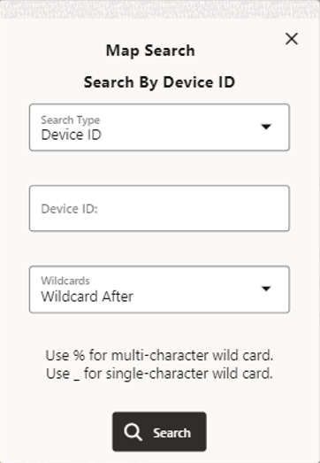
Based on your configuration, the Search Type drop-down list allows you to select the type of information to search for (such as Device ID, Customer Name, Account ID, and so on).
Note: The selected search type will populate the Search By title dialog box (for example, Search By Device ID in the screen capture above).
You may use a wild card search when you aren't sure of the value to search on. For example, in the NMS OPAL model, searching for F12% with Wildcard After selected, will return a Device ID Search Results panel with multiple potential matches.
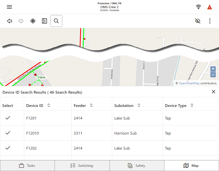
With the Search Results panel displayed, you may:
• Tap a row to focus on the device.
• Tap the check mark selection icon () to set the map focus on the search item and close the search results panel.
Showing and Hiding Layers of Information
Tap to display the Hide/Display panel. Options here show and hide different layers of information.
Hide/Display
• Landbase: Toggle the visibility of the Landbase (if one is selected in the Settings panel)
• Secondary: Toggles the visibility of the Secondary network.
• Structures: Toggles the visibility of structures such as poles
• Non-Main Asset DA: Toggles the visibility of non-main asset damage report symbols.
• Customer Calls: Toggles the visibility of the customer call locations.
Annotations
• Conductor Current Phase Markers: Toggles the visibility of phase indicators on conductors.
• Device Labels: Toggles the visibility of device labels
• Device Nominal Phase Labels: Toggles the visibility of devices' nominal phase(s). If a device is in an abnormal state the background of the label is colored green (abnormally open) or red (abnormally closed).
• Conductor Nominal Phase Labels: Toggles the visibility of conductors' nominal phase(s). If a conductor is in an abnormal state the background of the label is colored green (abnormally de-energized) or red (abnormally energized).
• Conductor Feeder Labels: Toggles the visibility of conductor feeder labels.
• Flow Direction: Toggles the visibility of flow direction arrows.
Crew Types
• All
• Line
• Trouble
• Guide
• Service
• Eval
• Tree Crew
Conductor Highlight
• Assessed
• Predicted De-Energized
• Confirmed De-Energized
• Confirmed Degraded
Using the Options and Settings Menu
Tap ( ) to access Map Options and Settings menu.
) to access Map Options and Settings menu.Settings
Tap the gear icon ( ) to display the Settings panel. Options here enable you change visualization and behavior of the Map. Note that the Map updates as you adjust them:
) to display the Settings panel. Options here enable you change visualization and behavior of the Map. Note that the Map updates as you adjust them:• Landbase Source: Enables you to select different landbases, including an offline landbase.
• Landbase Opacity: Select the visual intensity of the landbase.
• Show Offline Landbase when Offline: Automatically switches to the downloaded offline landbase when you are offline. When you reconnect your selected online landbase will be automatically restored.
• Map Theme: The Map theme can be changed to support low-lit or well-lit working environments. The following options are available:
• Automatic (Follow Theme): Inherits the Light or Dark theme selected in the main OMA Setting dialog.
• Dark: Displays the dark Map theme regardless of the currently applied theme.
• Light: Displays the light Map theme regardless of the currently applied theme
• Symbol Scale: Select the preferred symbol size/scale (applies to devices and symbols)
• Big Symbols: When selected displays preconfigured symbols larger when zoomed out.
• Big Symbol Scale: Select the scale of big symbols, when they are displayed.
• Line Scale: Select the thickness of conductors.
• Text Scale: Select the size of text displayed in labels
• Condition Distance Scale: Select the distance at which conditions and outage symbols display from their associated device.
• Conductor Highlight Blur: Display conductor highlighting with sharp edges, or with blurred edges.
• Conductor Highlight Opacity: Select the intensity/opacity of the highlighting.
• Conductor Highlighting Scale: Select the thickness of conductor highlighting.
• Trace Outline Opacity: Select the intensity/opacity of traces.
• Trace Outline Scale: Select the thickness of traces.
• Feeder Highlight Opacity: Select the opacity/intensity of non-selected feeders, when Feeder Highlighting is applied.
• Conductor Dashing Mode: Conductor line styles can be applied to indicate phasing or overhead/underground
• Underground Cables: Display underground conductors with dashed lines.
• Phase Count Dashes: Display number of phases as dashes.
• None: Do not display underground cable dashing or phase count dashes.
• Rotate Device Symbols: Display device symbols in the same orientation or aligned with the network.
• Device Labels Always to the Right: When selected, displays device labels to the right of the device.
• Do Not Move Map When Panels Open: When selected, as Map panels are displayed the Map does not move to accommodate the panel.
• Inertial Panning: When selected, the Map exhibits "momentum" after panning with the mouse or finger.
• Smoothly Animate Between Positions: When selected, the Map smoothly pans and zooms between different positions; for example when clicking Back or Forward, when targeting on nearby events, or displaying the extent of a trace.
• Auto-reset to Default Selection Mode: When selected, returns to the default Map selection mode automatically after using one of the alternate selection modes or when performing a measure distance operation. If this is not selected, then the map will remain in the selected mode (for example, geographic location selection or measure distance mode) until you choose a different mode.
After changing settings in this panel, click OK to apply the changes, or click Defaults to restore the factory settings.
The changes you apply here will be saved on your device.
Map Updates
Checks for available map updates and allows you to download them.
View
Options available here provide different views of the electrical network:
• Color by Feeder: When selected, colors the network feeder by feeder.
• Color by Phase: When selected, colors the network by phase.
• Color by Nominal Voltage: When selected, colors the network by nominal voltage.
• Color Secondary by Fixed Color: When selected, all secondary network will show with the configured fixed secondary color.
• Color Secondary by State: When selected, secondary networks that have state related styles will be styled according to the state. Any secondary network that is in a nominal state will show the configured fixed secondary color.
• Color Secondary by State and Mode: Similar to the Color Secondary by State option, but the nominal state conductors will follow the Feeder/Phase/Voltage coloring mode, just like non-secondary conductors.
• Show Nominal Network State: When selected, displays the nominal state of devices and conductors.
• Declutter Symbols: When selected, declutters the network when zoomed out.
• Map Color Legend: Displays the Map Color Legend dialog, which illustrates the colors, highlights, and line styles for the different electrical states, phases, and voltages.
Selection Options
Options here provide different ways of accessing and selecting objects on the Map.
•  Open / Close the Selection Panel: When selected, the Selection Panel will slide out each time an object is selected in the Map.
Open / Close the Selection Panel: When selected, the Selection Panel will slide out each time an object is selected in the Map.•  Select Map Location: Enables you to tap on a location on the Map, and display its geographic co-ordinates.
Select Map Location: Enables you to tap on a location on the Map, and display its geographic co-ordinates.• Single Touch Action: Select map objects with single touch action
• Circle Action: Select map objects with circle action
• Box Action: Select map object with box action
• Polygon Action: Select map object with polygon action
•  Measure Distance: You can measure distances on the Map
Measure Distance: You can measure distances on the Map• Tap on the map to add a start position.
• Move to a different position and tap again to create a turning point. Repeat as necessary.
• Tap on the last point to complete the measurement. The distance is displayed in the top-right corner of the Map.
• Tap anywhere in the Map to remove the measurement.
• Clear Selection and Action: Clears the selected objects from the Selection List panel and the map.
GPS Location
Options here provide access to location and tracking information:
• Track Current Location: Tracks your current location on the Map
• GPS Location: Provides options to focus the Map on your desired location.
• Goto GPS Location: Focuses the Map on your GPS location.
Goto GPS Location: Focuses the Map on your GPS location.• Select Map Location: Focuses the Map on a selected location.
Select Map Location: Focuses the Map on a selected location.• Directions to Location: Opens the device's native navigation app to assist you in driving to the task location.
•  Add Damage Report for Location: Allows you to create a damage report at the selected location.
Add Damage Report for Location: Allows you to create a damage report at the selected location.Navigation
• Show Map Search: Displays the Map Search dialog
Show Map Search: Displays the Map Search dialog• Find Assessments: Lists all of your active patrol assessment conditions. From the Assessment panel, you can select an assessment condition and the Map will focus on the condition.
Find Assessments: Lists all of your active patrol assessment conditions. From the Assessment panel, you can select an assessment condition and the Map will focus on the condition.• Back: Navigate back to the previously viewed Map position Forward: Navigate forward to a previously viewed Map position.
Back: Navigate back to the previously viewed Map position Forward: Navigate forward to a previously viewed Map position.Understanding the Selection and Traces Panel
The Selection and Traces panel is displayed when you select one or more objects on the Map, or tap Selection Panel icon.
The panel has 2 tabs – Selection and Trace.
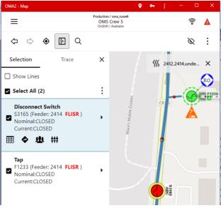
Selection Panel
This panel displays information about the selected object(s) in the Map. From here you can select the required object and perform actions on the object.
• Show Lines: When selected, selected conductors are displayed in the list of objects as well as devices and other assets
• Select All: Selects or deselects all items in the list
• Selection Options: Tap  to access Feeder Highlighting Options:
to access Feeder Highlighting Options:• For a selected device or conductor, tap Feeder Highlights ( ) then click Highlight Feeder. Other feeders will be displayed less prominently, but still be selectable (so you can highlight additional feeders).
) then click Highlight Feeder. Other feeders will be displayed less prominently, but still be selectable (so you can highlight additional feeders).• To remove or clear feeder highlighting, click to select the feeder then choose Unhighlight or Clear Highlighting. You can also clear highlighting from the Highlighting indicator displayed in the top-right of the Map.
Perform Actions on a Selected Object
Tap on an object in the list to display a list of actions.
Common actions are displayed as icons beneath the selected item:
Access to all related actions are available by tapping on the  icon:
icon:
icon: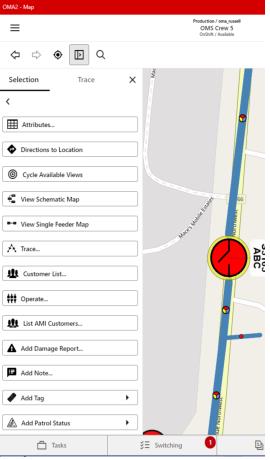
The potential list of actions is here:
• Attributes: Displays the Attribute List for the object.
• Directions to Location: Opens the devices native map/navigation system to the selected object
• Cycle Available Views: Focuses the map to an alternate view of the given object. Typically used to navigate the map between the geographic world and an internal view (substation).
• View Schematic Map: Focuses the Map on the object’s position in the schematic network view
• View Single Feeder Map: Focuses the Map on the object’s position in the Single Line network view
• Trace…: Switches to the Trace tab, which enables you to perform traces. See Traces, below
• Customer List: – Displays the list of customers downstream of the selected device.
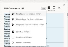
• AMI Customers: Displays a list of customers with smart meters.
• For a selected customer(s) you can send requests (ping) for meter information.
You can select all AMI customers in the list using the icon at the top of the dialog, and then choose the ping type from the icon:
• Operate: Enables you to operate the selected device:
• Select the phases to operate
• Enter the time the device was operated
• Select Assign to Me if you want to add a task to your list of tasks for this device operation.
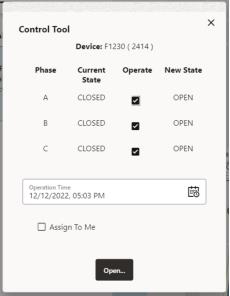
After tapping Open or Close, the Lookahead dialog is displayed:
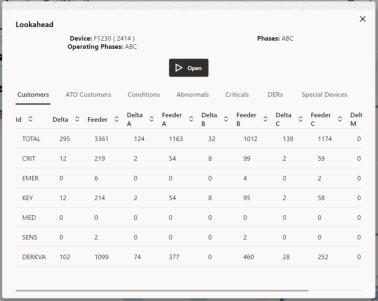
Visually verify the Customers and Conditions, then tap Open or Close to confirm the device operation.
• Add Damage Report: Enables you to create a damage assessment
• Add Note: Enables you to add a note to the Map
• Add Tag: Enables you to add different tag types, as per your configuration.
• Add Patrol Status: Enables you to add different patrolling conditions.
• Confirm Fault Location: Enables you to confirm a predicted fault location
• Mark Fault Incorrect: Enables you to confirm a predicted fault location as incorrect.
• Open Event: Opens the Event Details for the selected object.
• Open Patrol Event Details: Opens the Patrol Event Details
• Assign Event to me: Assigns the event to yourself
• Confirm Outage: Marks Probable Event as a Real Event
• Delete Condition: Delete Condition (tag, note, …)