Model Build Process
Model Build with a Preprocessor
In most cases, customers will place source data files into a designated directory and run the nms‑model‑build script. This script takes no arguments and builds whatever maps are recognized by the [project]‑maps‑to‑build script. When the build completes, any completed maps will have import files automatically placed in a designated directory. In some cases, models may be built directly from import files.
Customer Model Build Scripts
The following table describes the model build scripts.
Script | Description |
|---|---|
nms‑model‑build | Builds the maps recognized by [project]‑maps‑to‑build. Upon completion, the ${OPERATIONS_MODELS}/patches/done directory contains import files for the built maps. The script will check for a [project]‑model‑build script, if it exists, it will be called instead of running the rest of the nms‑model‑build script. Options -noprebuild -nopostbuild The parameters will cause the nms‑model‑build script to skip prebuild script execution or postbuild script execution. |
[project]‑model‑build | If a [project]‑model‑build script exists, it will be called by nms‑model‑build and will be used as the project configured script to run the model build process. Most projects will not use this script. |
[project]‑build‑map | Required for any model build process that has a model preprocessor. Takes a map name and generates an import file for that map. The resulting import file is placed in the $OPERATIONS_MODELS/patches directory. This script should preserve the .mp file time stamp if altered by any of its processing of the map data. See the OPAL‑build‑map as an example. |
nms‑build‑maps | This script takes multiple map prefixes as parameters. Any maps supplied will be built as a single model transaction. This is recommended when there is a model transaction involving multiple maps, especially if facilities are being transferred from one map to another. This script checks that there are no conflicting pending maps in separate work orders. Since this check takes a few seconds, it can be bypassed by setting the CES_PARAMETERS entry for 'NMS', 'CHECK_MAP_DEPENDENCIES' to 'false'. This does not run any ‑prebuild or ‑postbuild scripts. |
[project]‑maps‑to‑build | Required for all model build processes. Identifies and prints a list (single line, space separated) of all maps that are queued up to be built. Model .mb files in the patches directory should be included in the list of maps to build including the .mb extension. All other maps to build should be reported without extensions. The resulting list of maps may include the same map twice, once for a new map to be preprocessed and once for a map waiting to be applied from the patches directory. Use the OPAL‑maps‑to‑build as an example. |
[project]‑postbuild | Although not a required element of the model build, project-specific needs may call for an additional process after each model build. The additional process is carried out by the [project]‑postbuild script. It is run after the nms‑model‑build script builds a complete set of maps. Common reasons for this process include recalculations of control zones, a fresh extraction of the CUSTOMER_SUM table, or a recache of DDService. |
[project]‑prebuild | Although not a required element of the model build, project-specific needs may call for an additional process before each model build. The [project]‑prebuild script carries out the additional process. It is run before the nms‑model‑build script builds a complete set of maps. This process is rarely needed. |
Model Build with a Post-Processor
If a post-processor is needed for the model build, you should create and install the [project]‑postbuild script. If the post-processor requires patches to be applied to the model, it will build import files and put them in the patches directory. The nms‑build‑map script can be called with the ‑noVerify option to build each patch without user interaction.
Constructing the Model
To ensure correct model construction, complete these steps:
1. If a model build preprocessor is being used, make sure that the expected scripts are created and installed. These are [project]‑build‑map and [project]‑maps‑to‑build.
2. When new files are brought to the system, place them in the appropriate directory on the master server before initiating the model build.
• Import files should go into the ${OPERATIONS_MODELS}/patches directory.
• Preprocessor input files will probably go into a project-specific directory. An example of a commonly used directory is ${OPERATIONS_MODELS}/mp.
3. Log into the master server as the administrative user and initiate a model build by typing:
nms‑model‑build
Or, if you want to produce a build log, enter the following:
nms‑model‑build | tee model_build.$(date "+%Y%m%d.%H%M%S").log 2>&1
Result: Each import file will be processed, updating the Operating Model and Graphic Presentation files.
4. Wait for the user prompt before continuing further model build operations. This process may take some time.
5. Review the error output information contained in the errors directory.
The Model Build Preprocessor
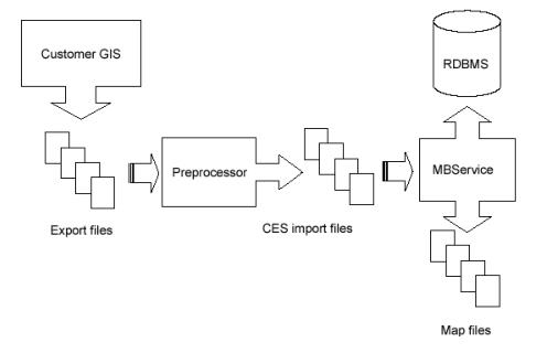
Oracle Utilities Network Management System obtains descriptions of the physical, electrical, and topological infrastructure from CAD, GIS and AM/FM systems through the model builder and associated preprocessors. The purpose of a preprocessor is to extract information from a source (GIS, CAD, AM/FM, etc.) and convert it to the neutral Oracle Utilities Network Management System import (.mb) format. From this format, it is processed by the model builder to determine and apply actual changes to the Oracle Utilities Network Management System operations model.
When the product is to be configured for a customer, there is a need to populate the corresponding Operations Model. Typically customers will have data stored within one or more forms: within a GIS, within a CAD product, in an RDBMS, or in flat files.
The information within these forms can either be directly extracted or preprocessed to a form which can be presented to the Model Build interface.
Model Build Basics
Model Build is a process of steps that will generate an operational topological representation of client’s existing GIS. A single segment of data (partition) passes through four stages during its incorporation into the Operations Model:
• Model Build (MB Service)
The following figure provides an overview of the model build process:
Extraction
The graphical representations of objects that will be modeled, along with the associated attributes, are grouped and exported into external files in a format that the preprocessor is capable of reading. It is at this stage that the partitioning of the model into geographic grids or schematic diagrams is typically determined. These partition file names must match the partition name, as identified within the file, with the requisite file extension.
Preprocessing
The preprocessor reads the files generated by the extraction process and constructs an Import file which models the extracted portion. The preprocessor tends to be a major development task, taking weeks or months to complete.
Model Build
The Model Build (or MB Service) parses the Import file, verifies basic model consistency, applies the contained changes to the Operations Model Database, and commits the changes as part of the final model.
Completed Operations Model
The completed model consists of new or updated partitions and new or revised entries within the core model database schema.
Model Preprocessor
The preprocessor reads (parses) the files generated by the extraction process and constructs an import file that accurately models the extracted portion. The end result of completing a preprocessor is a script that is capable of accepting customer source GIS data files and generating import files.
The Model Preprocessor can be broken into individual stages called: Parse, Post Parse, Cell Explosion, Post Explode, Topology Construction, Post Topology, and Model Build Import file generation.
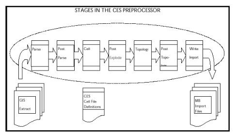 The following figure illustrates the stages in the preprocessor:
Parse Stage
The Parser reads the client GIS model from external files created by the Extraction process into a data structure known as an Entity Set. After this phase is completed, the resulting Entity Set will be a ‘skeleton’ for the complete model. The activities completed in this stage are not client specific; it will be more specific to a standard data file format (e.g., AutoCAD’s DXF format, Intergraph’s ISFF format, etc.). Each individual graphical object (e.g., point, line, or text) will be represented in an output file.
• Post Parse: Client specific processing that is used to accommodate any modification of the data that may be required prior to Cell Explosion.
• Cell Explosion: Cell explosion is the central phase of preprocessing. It is here that the conversion of the raw graphical objects to model objects is accomplished. The graphical objects are mapped to objects, which will appear in client’s final model.
• Post Explode: Allows for client specific processing after Cell Explosion.
• Topology Construction: The inter-device connectivity for all electrical objects is constructed in this stage. The connectivity can either be explicit (i.e. ‘To’ and ‘From’ node identifiers) or based on proximity.
• Post Topology: The final opportunity for client specific processing.
• Model Build Import File Generation
Cell Explosion
The central phase of preprocessing is the conversion of graphical objects into full-fledged model objects; this conversion from a graphical object to a model object can involve a wide range of operations. These operations are specified in a text file [client]_devices.cel, which is called the explosion definition file.
The operations that may be accomplished during this phase include the following:
• Handle Assignment: This requires that a graphical entity be mapped to a particular class of model objects (for example, switch, transformer, device annotation, road, water boundary, etc.) and that an index number, unique within that class, be assigned to this object.
• Attribute Manipulation: Attributes can be added, removed or renamed. They can also be assigned new values based upon combinations of other attribute values or the result of mathematical calculations.
• Expansion/Replacement of One Object by Multiple Objects: For example a transformer in the mapping system could be exploded into a transformer with a switch and a network protector.
• Creation of Aggregate Objects: One object may be used to represent a group of objects. For example, a recloser object may in fact represent the recloser along with a by-pass switch, a load switch, and a source switch. All of these component objects may be created and bundled into a single aggregate object during this phase.
• Elimination of Un-Necessary Objects: Any object not explicitly ‘matched’ during this phase will be eliminated; thus, this stage acts as a filter.
• Assignment of Core Properties: For example, phase, nominal status, NCG, and symbology can be assigned as default values for all devices.
• Daughter Object Creation: Creating new entities based upon information taken from an existing object.
• Classification of Objects as Background: Sets the location of an object to a background partition.
• Diagnostic Messaging: Aids in debugging or as a method to configure customer specific error messages with customer defined attributes.
Model objects have handles (class and index), attributes and aliases, geometry, and optionally aggregate object specification, all of which are supported through the explosion preprocessor.
To understand the cell definitions, which specify how an object is recognized and processed during cell explosion, one should understand two fundamental ideas:
1. "Parent" and "daughter" objects
2. String expansion.
Parent and Daughter Objects
Those objects, which enter the cell explosion process from the parser (or the post-parse processing) and which are recognized (or matched) by a definition, are considered to be "parent" objects (or, at least, potential parents); any new graphic objects created by the cell definition which matched the parent are considered "daughter" objects.
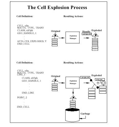
There are 4 outcomes for an object after cell explosion:
1. The parent object may pass through and be modified by cell explosion without giving rise to daughter objects.
2. The parent object may pass through cell explosion while giving rise to one or more daughter objects.
3. The parent object may be eliminated by cell explosion yet give rise to daughter objects, which survive and proceed to the succeeding stages.
4. The parent object may be eliminated by cell explosion and not give rise to daughter objects.
Note: Any object that has an attribute named "CES_EXPLODED" with a value of "Y" will pass through this process; all other objects are eliminated.
Commonly, if the parent gives rise to daughter objects, the parent dies, but transfers some of its attributes to the resulting daughters through use of the ATT keyword.
The following illustration depicts outcomes 1 and 2 for an object:
String Expansion
When assigning new attributes, you may want the values for these new attributes to be formed from existing attributes, either by simply copying an existing value, or by combining and/or transforming the old values. This process is accomplished by "string expansion" which replaces or expands an attribute name into the full string representing that attribute’s value. In cell definitions, enclosing an attribute name in square brackets indicates that you intend for this attribute name to be expanded; for example, the form "[FEEDER_ID]" will be replaced by the value of the FEEDER_ID attribute, such as "6992" (assuming that such an attribute exists for the matched object). In addition to this simple expansion, there are several specialized forms of string expansion that can be summarized as follows:
1. Substring
• Delimiter Based
Indicated by "<"or ">". This this form returns the substring before or after the first occurrence of the delimiting character. The delimiting character is the character immediately following the "<" or the ">".
For example, if TAG= "XYZ.553", then [<.[TAG]] returns the substring preceding the first period (".") in the TAG attribute value, in this case, "XYZ". Likewise, [>.[TAG]] returns the substring following the period, which would be "553".
Note: When nesting a simple expansion form (e.g., [TAG]) within a delimiter based expansion form; you can discard the inner square brackets. Thus, "[<.TAG]" is equivalent to "[<.[TAG]]".
• Position Based
Indicated by "@" -- this form returns the substring beginning and ending at the given character positions.
Using the example from above where TAG="XYZ.553", the notation [@(1:2)[TAG]] extracts the substring from the value of the TAG attribute, which begins with character position 1 (position 0 being the first character) and ends with character position 2. In other words, it extracts a two-character substring, beginning from the second position, returning the value "YZ".
Note: The character position can be specified relative to the end of the string by using the "$" character to represent the last position in the string. For example, "[@($-1:$)[TAG]]" returns the last two characters "53". Also note that a single character can be extracted by specifying the start and end positions as the same character, e.g., "[@(2:2)[TAG]]" returns the third character, "Z".
2. Codelist
These can be used to map or convert an input value into the corresponding output value.
• Basic Lookup Table:
To create the "lookup table", we use the CODE keyword. The format for the table is:
CODE, [listname] ,input value, outputvalue.
For example:
CODE, RANK_LIST, E, 1
CODE, RANK_LIST, R, 2
CODE, RANK_LIST, P, 4
Creates a lookup table with three entries or mappings.
(A default code, returned when the given input value is not in the table, can be defined for a list using the DEFAULT_CODE keyword; for example, DEFAULT_CODE, RANK_LIST, 1 means that any input value other than E, R or P results in the output of a "1".)
To actually look up or convert a value, we use the codelist form of string expansion, indicated by a "%".
[%RANK_LIST.[RANK_CODE]]
Will return "1" if the RANK_CODE attribute is "E"; "2" if the RANK_CODE is "R"; and "4" if the RANK_CODE is "P".
• Database Lookup:
This works the same as the basic lookup table but the entries are stored in a database table. There are 2 formats for database lookups:
• DBCODE
The table name (which also serves as the list name), the input column name, and the output column name are defined using the DBCODE keyword. The format for the DBCODE is:
DBCODE, [tablename], [input column], [output column]
For example:
DBCODE, feeder_ncg, feeder_name, ncg_id
Means that there exists a database table called "feeder_ncg" which has an input value column called "feeder_name" and an output value column "ncg_id".
• NAMED_DBCODE
NAMED_DBCODE is similar to DBCODE except it takes a list name that is different from the table name. It is used in cases where there is a need for 2 codelists based on the same database table but with different input and output columns. The format is:
NAMED_DBCODE, [listname], [tablename], [input column], [output column>]
A default code, returned when the given input value is not in the table, can be defined for a list using the DEFAULT_CODE keyword. For example, DEFAULT_CODE, feeder_ncg, 1 means that any input value other than what has been defined results in the output of a "1". Additionally, a special DEFAULT_CODE value can be assigned with the value specified as "--INTEGER_SEQUENTIAL--".
For example:
DBCODE, feeder_ncg, feeder_name, ncg_id
DEFAULT_CODE, feeder_ncg, --INTEGER_SEQUENTIAL--
DEFAULT_CODE, feeder_ncg, --INTEGER_SEQUENTIAL--
Means if a lookup into the table named feeder_ncg does not have a match, the default action will be to select the maximum value of ncg_ids in the table, add one to the ncg_id, and create a new record with the given feeder name and the incremental maximum ncg_id.
Accessing the table is the same as the basic lookup table mentioned above.
• Math Functions
Mathematical functions can be calculated by using the input value to access a "pseudo-codelist." "List name" has one of the following values:
MATH_SIN
MATH_COS
MATH_TAN
MATH_ASIN
MATH_ACOS
MATH_ATAN
MATH_LOG
MATH_LOG10
MATH_EXP
MATH_SQRT
MATH_CEIL (round up to next greatest number)
MATH_FLOOR (round down to next lowest number)
MATH_FABS (absolute value; for example, -4.5 becomes 4.5)
MATH_RPN (math function in reverse polish notation)
For example, to calculate the sine of an ANGLE attribute:
[%MATH_SIN.[ANGLE]]
• Coordinate Lookup:
The coordinates of an object can be accessed using a form that mimics a codelist lookup:
[%COORDINATE.FIRSTX] returns the first X coordinate of the object
[%COORDINATE.LASTX] returns the last X coordinate of the object
[%COORDINATE.FIRSTY] returns the first Y coordinate of the object
[%COORDINATE.LASTY] returns the last Y coordinate of the object
3. Default Value
A default value can be specified which will be returned if the result of string expansion would otherwise be an empty string. This is indicated by enclosing a default value between two caret symbols ("^").
For example: "[^PRIMARY^[PRI_CIRCUIT_ID]]" returns a value of "PRIMARY" in any case where the PRI_CIRCUIT_ID attribute is non-existent or empty.
If a default value is not specified, then a "String Expansion Error" message will occur.
4. Special Attributes
Some properties of an object can be accessed as if they were attributes by using one of the special names given below, preceded by a double dollar sign:
CLS (cell number)
IDX (index number)
X1 (1st or primary X coordinate)
Y1 (1st or primary Y coordinate)
Xn (subsequent X coordinate)
Yn (subsequent Y coordinate)
COORD_CNT (number of coordinates)
MAP_CLASS (class number of partition)
MAP_NAME (full name of partition)
CELL_NAME (cell name; the set of instructions for an object)
CLS_NAME (actual name of class rather than number)
For example, [$$CELL_NAME] returns the name of the "cell" within the cell definition file that was matched by the current object.
5. Handle Reference
One daughter object can access the class and index number of another daughter object by using the following two forms:
$<#>.CLS
$<#>.IDX
$<#>.IDX
For example, in daughter object #2, the class number of daughter #1 can be accessed by the form: "[$1.CLS]" and index number of daughter #1 can be accessed by the form: "[$1.IDX]".
Note: A common practical application of this form of string expansion is to assign the DEVICE_CLS and DEVICE_IDX attributes of a SND attached to its corresponding transformer.
Available Cell Explosion Keywords
This section provides descriptions, syntax, and examples for available cell explosion keywords.
Global (outside all cell definitions)
• CODE - Defines an entry in a code conversion lookup table. See String Expansion Section.
• DBCODE - Defines an entry in a database table. See String Expansion Section.
• DEFAULT_CODE - Sets default values for codelist. See String Expansion Section.
• INCLUDE - Reads definitions from another file.
INCLUDE, <name of file to include>
INCLUDE, /users/xyz/data/xyz_devices.cel
• NAMED_DBCODE - Allows for definitions of more than one codelist from a single database table.
• TEMPLATE - Uses a template definition.
• USE - Sets default values for an entity’s properties.
USE, [KEYWORD], [value]
USE, PHASE, abc
Shared (used by both parent objects & daughter graphic objects)
• ATT[n]: - Sets the value of an attribute. There is no limit on the number of ATT[n] records that can exist in the cell definitions. [n] is currently a placeholder, usually set to 0 (zero).
ATT[n], [att_name], [att_value]
ATT0, feeder, [@(9:12) [ACAD_layer]]
ATT0, riser, N
ATT0, riser, N
• ATTR_INDEX - The string that follows this keyword will be used to assign an index unique for an object of this object’s class; usually, the string will be formed by expansion of one or more attributes.
ATTR_INDEX, [n]
ATTR_INDEX,
• BND_HANDLE - Indicates that the index for this object should be provided by the boundary-node handle manager.
BND_HANDLE, 1
• CLASS - Sets the class of object to explicit value.
CLASS, <class name>
CLASS, Xfm
• DATT[n] - Dynamic attribute name. [n] is currently a placeholder, usually set to 0 (zero).
DATT[n], <att_name>, <att_value>
DATT1, [%LOCATION.[^0^[WITHIN_SITE_IPID]]],~
4901.[^0^[WITHIN_SITE_IPID]]
4901.[^0^[WITHIN_SITE_IPID]]
• DIAGRAM_ATT_<att_name> - Accesses the attribute of the diagram:
STRING, [DIAGRAM_ATT_TEXT]
HEIGHT, [%MATH_RPN.[DIAGRAM_ATT_Size] 0.4 *]
ANGLE, [DIAGRAM_ATT_ANGLE]
• GEO_HANDLE - Indicates that a unique index should be generated based upon the object’s class and geographical coordinates.
GEO_HANDLE, 1
• INDEX - Sets the index of object to an explicit value.
INDEX, <n>
INDEX, 533
• MARK_BGD - Marks an object as background and sets its location to the background partition.
MARK_BGD, 1
• MSG[n] (or MESSAGE[n]) - Prints a message to standard output when this definition is used, where [n] is either 0, 1, 2, or 3.
MSG[1|2|3], <message text>
MESSAGE[1|2|3], <message text>
MESSAGE[1|2|3], <message text>
MSG1, Warning: Found stray fuse
MSG2, Handle: [$$CLS] . [$$IDX]
MSG3, At (X,Y) of ([$$X1],[$$Y1])
MSG2, Handle: [$$CLS] . [$$IDX]
MSG3, At (X,Y) of ([$$X1],[$$Y1])
• NCG - Set the entity’s Network Control Group (NCG) property. (Program-style preprocessor only)
NCG, <n>
NCG, [@(9:12)[ACAD_layer]]
• NOMINAL_STATE - Sets the entity’s ‘NOMINAL_STATE’ property. The value can be an integer typically between 0 and 15 or the key words OPEN or CLOSED.
NOMINAL_STATE, [n]|OPEN|CLOSED
NOMINAL_STATE, CLOSED
• OPT_ATT[n] - Sets an optional value of an attribute. Will not report a string error message if the value fails on attribute expansion. [n] is currently a placeholder, usually set to 0 (zero).
OPT_ATT[n], [att_name], [att_value]
OPT_ATT1, From_Node_Bnd, [NODE1_BND]
• OPT_DATT[n] - Sets an optional dynamic attribute name. Will not report a string error message if the attribute name fails on attribute expansion. [n] is currently a placeholder, usually set to 0 (zero).
OPT_DATT[n]
OPT_DATT1, [%LOCATION.[^0^[WITHIN_SITE_IPID]]],~
4901.[^0^[WITHIN_SITE_IPID]]
4901.[^0^[WITHIN_SITE_IPID]]
• PHASE - Sets the entity’s ‘PHASE’ property (e.g., to ABC).
PHASE, [n]
PHASE, [%PHASE_LIST.[@(6:8)[ACAD_layer]]]
• STRING - Sets the value of the text string for this entity. (TEXT objects only)
STRING, [string]
STRING, [kVAr]
• SUB_BND - Indicates that this object is a substation boundary node and that its index should be assigned based upon the supplied string (usually the feeder or circuit identifier).
SUB_BND, 1
• SYM_ID - Sets the symbology-state-class to an explicit value, rather than its default value, which is the same as the class number.
SYM_ID, [n]
SYM_ID, 1304
• VOLTS - Sets the entity’s ‘VOLTS’ property. (Program-style preprocessor only)
VOLTS, [n]
VOLTS, [voltage] 1000 *
Parent Object ("explosionDef") Only
• AGGREGATE/_ POINT/_LINE/_TEXT - Creates a graphic object of the specified kind that becomes a component of the overall aggregate device. AGGREGATE and AGGREGATE_LINE require 2 coordinates; AGGREGATE_POINT and AGGREGATE_TEXT require one coordinate. All AGGREGATE definition types require an END_AGGREGATE. (Obsolete)
AGGREGATE, [n]
AGGREGATE, 4
AGGREGATE_ POINT, [n]
AGGREGATE_POINT, 1
AGGREGATE_ LINE, [n]
AGGREGATE_ LINE, 3
AGGREGATE_ TEXT, [n]
AGGREGATE_ TEXT, 2
• CELL - Begins the definition for one device type. The cell definition file can contain many sets of cell definitions. All CELL definitions require an END_CELL.
CELL, [name]
CELL, uxfm2
• END_CELL - Ends an explosion definition.
END_CELL
• END_AGGREGATE - Ends an aggregate definition.
END_AGGREGATE
• END_TEMP – Ends a template definition.
END_TEMP
• MATT[n] - Matching attribute of the object to explode. [n] is currently a placeholder, usually set to 0 (zero). There is no limit on the number of MATT[n] records a cell explosion definition may have, but for the explosion to occur, all must match.
MATT[n], [attribute name], [target attribute value]
MATTO, ACAD_objectType, INSERT
• POINT/LINE/TEXT - Creates a "daughter" graphic object of the specified kind. All POINT/LINE/TEXT definitions require an END_POINT/LINE/TEXT.
POINT, [n]
POINT, 3
LINE, [n]
LINE, 1
TEXT, [n]
TEXT, 5
• POINT/LINE/TEXT WHEN [condition] - Creates a "daughter" graphic object of the specified kind when the given condition is met. All POINT/LINE/TEXT definitions require an END_POINT/LINE/TEXT.
POINT WHEN [condition]
POINT WHEN
LINE WHEN [condition]
LINE WHEN
TEXT WHEN [condition]
TEXT WHEN
• POINT/LINE/TEXT FOR [variable] IN [List of Values] - Creates zero, one or multiple graphic objects of the specified kind, one object for each value in the supplied list. Use [variable] within the definition as if it were an attribute name. A special variable called "$$ICOUNT" can also be used to retrieve the number of the iteration. All POINT/LINE/TEXT definitions require an END_POINT/LINE/TEXT.
POINT FOR [variable] IN [list of values]
POINT FOR
LINE FOR [variable] IN [list of values]
LINE FOR
TEXT FOR [variable] IN [list of values]
TEXT FOR
• POINT/LINE/TEXT FOR [num-value] TIMES - Creates zero, one or multiple graphic objects of the specified kind; number of objects specified by <num-values>. ($$ICOUNT can be used just as for the previous form). All POINT/LINE/TEXT definitions require an END_POINT/LINE/TEXT.
POINT FOR [numeric value] TIMES
POINT FOR
LINE FOR [numeric value] TIMES
LINE FOR
TEXT FOR [numeric value] TIMES
TEXT FOR
• REQUEST_HANDLE - Indicates that the existing handle of this object should be replaced with one supplied by the Explosion manager’s "ExplodeHandle" class. (Primarily for ISFF)
REQUEST_HANDLE, 1
• RMV[n] - Removes an attribute. [n] is currently a placeholder, usually set to 0 (zero).
RMV[n]
RMV0, voltage
• RNA[n] - Renames an attribute. [n] is currently a placeholder, usually set to 0 (zero).
RNA[n], [att_name], [new_att_name]
RNA0, amp_content, amp_cont
• TEXT_SCALE - Specifies the scale factor for text. Used to allow the height of base text symbol to be used as a multiplier to the cell definition specified coordinates.
TEXT_SCALE, [n]
TEXT_SCALE, 1
for example with the TEXT_SCALE, 1 specified and the base text object has a specified height of 400 and the COORD1, 10, 30 is specified, the resulting coordinates will be 400x10, 400x30 or 4000, 12000.
• USE_REFERENCE - Indicates that the index for this object should be based upon its corresponding reference object. (ISFF only) (Obsolete). For example:
USE_REFERENCE, 1
causes the FRAMME RB_REFPRMRY and RB_REFSCNDRY linkages to be used instead of the normal RB_PRIMRY and RB_SECNDRY.
Component "Daughter" Object ("explosionGrObject") Only
• ABSOLUTE_COORDS - Indicates that coordinate values are specified in absolute, "real-world" numbers; this over-rides the default behavior which is for numbers used in COORD statements to be taken as relative to the insertion point of the parent object (i.e. this insertion point corresponds to COORD 0.0, 0.0).
ABSOLUTE_COORDS, 1
• ANGLE - Sets the text rotation for this entity. Horizontal is zero and the angle proceeds counter clockwise. (TEXT objects only)
ANGLE, [a]
ANGLE, 90
• COORD/COORD[n]- Sets relative/absolute coordinate of an object/endpoint.
COORD, [x], [y]
COORD, 1.0, 2.5
COORD[n], [x], [y]
COORD1, 0.0, 1.0
COORD2, 1.0, 2.0
COORD2, 1.0, 2.0
• COMPONENT[n] - Sets the aggregate sequence number and cell component number for a single component in the aggregate.
COMPONENT[n], [agg_seq_num], [cell_comp_num]
COMPONENT1, 1, 2
• END_AGGREGATE - Ends the definition of component graphic object.
END_AGGREGATE
• HEIGHT - Sets the text height for this entity. (TEXT objects only)
HEIGHT, <h>
HEIGHT, 2
• H_ORIENTATION - Sets the horizontal justification of text. Values can be LEFT, CENTER, or RIGHT, or 0, 1, or 2. Default is LEFT. (TEXT objects only)
H_ORIENTATION, [n]|LEFT|CENTER|RIGHT
H_ORIENTATION, LEFT
• USE_ROTATION - Indicates that the rotation property of the original entity should be used to set the rotation for the component graphic object.
USE_ROTATION, 1
• V_ORIENTATION - Sets the vertical justification of text. Values can be TOP, CENTER, or BOTTOM, or 0,1, or 2. Default is BOTTOM. (TEXT objects only)
V_ORIENTATION, [n]|TOP|CENTER|BOTTOM
V_ORIENTATION, 2
Special Attributes Set by Explode an Processed by mat2entityset.(script-preprocessor):
• Alias - Sets an alias for an attribute (both script- and program-style preprocessors).
ATT[n], ALIAS[dbtype], [value]
ATT0, ALIAS[OPS], [LOC_NUM]
• Diagram-id - Sets the Diagram Id.
ATT[n], DIAGRAM_ID, [value]
ATT1, DIAGRAM_ID, [IPID]
• Group – Sets the Group code.
ATT[n], CES_PP_GROUP|GROUP|Group|group, [value]
• Local
ATT[n], LOCAL|Local|local, [value]
• Locations (not to be confused with LOCATIONS)
ATTN[n],CES_LOCATION, [value]
ATT1, CES_LOCATION, 4901.[MID]
ATTN[n], CES_LOCATION_DEFINITION, [value]
ATT1, CES_LOCATION_DEFINITION, 4901.[MID]
ATT[n], CES_LOCATION_NAME, [value]
ATT1, CES_LOCATION_NAME, Pole [^?^[SUPPORT_NO]]
ATT[n], CES_LOCATION_DESC, [value]
ATT1, CES_LOCATION_DESC, Pole defined by support/switch:~
[^?^[SUPPORT_NO]]/[^?^[SWITCH_NAME]]
[^?^[SUPPORT_NO]]/[^?^[SWITCH_NAME]]
ATT[n], CES_LOCATION_REFERENCE, [value]
ATT1, CES_LOCATION_REFERENCE, [%COORDINATE.FIRSTX],~
[%COORDINATE.FIRSTY]
[%COORDINATE.FIRSTY]
Network Control Group
ATTN[n], NCG|Ncg|ncg, [value]
ATT1, NCG, [%feeder_ncg.[^UNKNOWN^[DISTRICT]]_ ~
[%ncg_volt.[^UNKNOWN^[VOLT_LEV]]]]
[%ncg_volt.[^UNKNOWN^[VOLT_LEV]]]]
• Rank
ATT[n], RANK|Rank|rank, [value]
ATT1, RANK, [%MATH_RPN.[%RANKU.[^NO^[URBAN]]]~ [%RANKLC.[^UNKNOWN^[LINE_CATEGORY]]] + ~ [%RANKV.[^0^[VOLT_LEV]] [^0^[VOLT_LEV]]] + ~ [%RANKB11.[^0^[VOLT_LEV]] [^UNKNOWN^[DISTRICT]]] + ~ [%RANKP.[^RYB^[PHASING]]] +]
• Physical Property
ATT[n], CES_PHYS_PROP|PHYS_PROP|Phys_Prop|phys_prop|physical_property, [value]
ATT0, CES_PHYS_PROP, [%MATH_RPN.[%PHYS_PROP.BACKBONE] [%PHYS_PROP.~ [^OH^[OH_UG]]] +]
• Topology Specific
ATT[n], From_Node, [value]
ATT1, From_Node, [FROM_NODE]
ATT[n], To_Node, [value]
ATT1, To_Node, [TO_NODE]
ATT[n], Unique_id, [value]
ATT1, Unique_Id, [FROM_NODE]_[TO_NODE]_FID
• Transition
ATT[n], TRANSITION_ID|Transition_ID|Transition_Id|transition_id, [value]
ATT1, TRANSITION_ID, 120
• Voltage
ATT[n], VOLTAGE|Voltage|voltage, [value]
ATT1, VOLTAGE, [%VOLTS.[^UNKNOWN^[OPERATING_VOLTAGE]]]
Format for the Explosion Definition File
Devices are recognized, or ‘matched’, and appropriate manipulations are made based upon the descriptions or definitions contained in an explosion definition text file.
The general format for a single cell definition is as follows:
CELL, [cell-name]
[match-criteria]
[ [parent-object-actions] ]
[ [daughter-object-actions] ]
END_CELL
Remember, any object that has an attribute named "CES_EXPLODED" with a value of "Y" will pass through the explosion process (ATTO, CES_EXPLODE, Y); all other objects are eliminated.
Syntax
Cell Definition
1. One statement per line (the ~ can be used to continue on more than one line).
2. Comments begin with # and must be on a line by themselves.
3. Lines begin with keywords (always upper case).
4. Commas separate keywords and values.
Value fields can be:
• Attribute substituted using the syntax [<att name>] where the value of the <att name> for the currently exploded object will be substituted in the value string. See the examples in the line definition above.
• Math functions in Reverse Polish Notation (RPN) with space delimitation. The keywords which support RPN automatically are:
• ANGLE
• HEIGHT
• H_ORIENTATION
• INDEX
• NCG
• NOMINAL_STATE
• SYMBOLOGY
• VOLTS
• V_ORIENTATION
For example, the following will be valid:
COORD, 100.0, 300.0
COORD, 100.0 [X_OFFSET] +, 300.0 [Y_OFFSET] +
COORD, [X_OFFSET], [Y_OFFSET]
COORD, 100.0 [X_OFFSET] +, 300.0 [Y_OFFSET] +
COORD, [X_OFFSET], [Y_OFFSET]
Math operators supported include +, -, *, /, % (modulus) and ^ (exponentiation).
During the Parse phase of the preprocessor, the customer’s raw data files are converted into an internal data structure known as an Entity Set wherein each individual graphical object is represented by an Entity object. Each Entity object is read into the cell file and is processed separately. When creating a cell definition file, to decrease processing time:
1. Place filter cells at the top of the file. For example, cells with nothing but match criteria that will not be exploded.
2. Place cells with most abundant objects near the top of the file. For example, if a file contains 20 switches, 10,000 text objects and 500 transformers, place the text objects first, transformers next, and finally the switches.
3. Place most restrictive criteria cells for objects above general. Overhead transformers should be placed above generic transformers in the cell definition file.
Match Criteria
1. Use keyword MATT[n].
2. Basic form: MATT[n],<attribute name>,<target attribute value>.
3. Attribute name can be replaced by a string expansion.
4. Can use alternation of target values separated by |.
MATTO,[ACAD_layer],15kv-Bus|24kv-Bus|161kv-Bus
5. Multiple match criteria are logically "AND" ed together. All MATT[n] must return true before that cell will be used. For example, for the following cell to be used for an Entity object, all 3 lines must return true:
CELL, 01XF1
MATTO, ACAD_objectType, INSERT
MATTO, ACAD_blockName, 01XF1
MATTO, [@(1:3) [ACAD_layer]], PRI
…
Conditional Expressions
These have the form:
( (Boolean-Expression) ? true value | false value )ATT0, ALIAS[OPS], ( ([location]) ? [location]|D:[ATTR] )
The supported syntax for Boolean expressions within cell-definition files is as follows:
<Expression> = <Expression> && <Expression>
<Expression> || <Expression>
!<Expression>
(Expression)
<String-Comparison>
<Numeric-Comparison>
<Term>
where
<String-Comparison> = <String> == <String>
<String> != <String>
<String> < <String>
<String> > <String>
<String> <= <String>
<String> >= <String>
where
<Numeric-Comparison> = <Number> .eq. <Number>
<Number> .ne. <Number>
<Number> .lt. <Number>
<Number> .le. <Number>
<Number> .gt. <Number>
<Number> .ge. <Number>
where
<Term> = <String> | <Number> | <Function-Call>
where
<String> = <Simple-String> | <Expand-Form>
where
<Simple-String> = double-quoted string of alphanumeric characters (e.g., "553").
<Expand-Form> = attribute or property name enclosed in square brackets (e.g., [att_name])
<Number>
<Function-Call> = name of a standard function with argument(s) enclosed in matched parentheses.
Note: At present no standard functions have been implemented, so this feature should not be used.)
Operators are evaluated in the following order, with top most operators processed first. The operators used are:
!
< > <= > >= .lt. .gt. .le. .ge.
== != .eq. .ne.
&&
||
Examples:
([Layer] .eq. 501)
(([ObjectType] != "Primary Conductor") && ( [FeederId] .ne. 6800 ))
( sin(Rotation) < 0.5 )
( ![UniqueId] )
Example of Cell Definitions
Transformer with Supply Node
CELL, OverheadTransformer
MATT0, CESMP_OBJ_CLASS, Transformer
MATT0, [OhUg], OH
MATT0, DIAGRAM_ID, Symbol
LINE, 1
ABSOLUTE_COORDS,1
COORD1,[$$X1],[$$Y1]
COORD2,[$$Xn],[$$Yn]
# Definition attributes
CLASS, xfm_oh
SYM_ID, 2060[%phase_num.[^ABC^[Phase]]]
ATTR_INDEX, [GUID]
ATT0, ALIAS[OPS], [DeviceId]
ATT0, ALIAS[GIS], [GisId]
NCG, [%feeder_ncg.[CESMP_MAPNAME]]
ATT0, NCG_FDR, [CESMP_MAPNAME]
# Topology definition
PHASE, [%phase_map.[^ABC^[Phase]]]
NOMINAL_STATE, [%status_lookup.[^CLOSED^[NominalStatus]]]
VOLTS, [%voltage.[^4160^[Voltage]]]
PHY_PROPERTIES, [ces_physical_property]
ATT0, From_Node, [_Connector0])
ATT0, To_Node, [_Connector0]_SND
RANK, [%phase_bit.[^ABC^[Phase]]]
[%voltage_bit.[%voltage.[^4160^[Voltage]]]] +
[%voltage_bit.[%voltage.[^4160^[Voltage]]]] +
# Attribute mapping
OPT_ATT0, facility_id, [GisId]
OPT_ATT0, device_name, [DeviceId]
OPT_ATT0, feeder_id_1, [FeederName]
OPT_ATT0, feeder_id_2, [FeederName2]
# Explode this object
ATT0, CES_EXPLODED, Y
END_LINE
POINT, 6
CLASS, SND
ATTR_INDEX, [GUID]
PHASE, [%phase_map.[Phase]]
SYM_ID, 994
NCG, [%feeder_ncg.[CESMP_MAPNAME]]
COORD, 0, -1
ATT0, Unique_Id, [_Connector0]_SND
ATT0, device_cls, [$1.CLS]
ATT0, device_idx, [$1.IDX]
ATT0, device_id, [DeviceId]
ATT0, feeder, [$$MAP_NAME]
ATT0, phases, [%phase_num.[Phase]]
ATT0, ncg, [%feeder_ncg.[CESMP_MAPNAME]]
ATT0, CES_EXPLODED, Y
END_POINT
END_CELL
Code Lookup Examples
This example shows how a lookup table can be used to convert the GIS phase to an NMS phase:
# CODE phase_map
#
CODE, phase_map, 1, A
CODE, phase_map, 2, B
CODE, phase_map, 4, C
CODE, phase_map, 3, AB
CODE, phase_map, 5, AC
CODE, phase_map, 6, BC
CODE, phase_map, 7, ABC
CODE, phase_map, A, A
CODE, phase_map, B, B
CODE, phase_map, C, C
CODE, phase_map, AB, AB
CODE, phase_map, BA, AB
CODE, phase_map, AC, AC
CODE, phase_map, CA, AC
CODE, phase_map, BC, BC
CODE, phase_map, CB, BC
CODE, phase_map, ABC, ABC
CODE, phase_map, CBA, ABC
CODE, phase_map, BCA, ABC
CODE, phase_map, BAC, ABC
CODE, phase_map, CAB, ABC
CODE, phase_map, Unknown, ABC
CODE, phase_map, Null, ABC
DEFAULT_CODE, phase_map, ABC
This example is for using a lookup table (codelist) that is stored in a database table.
# CODE feeder_ncg
#
DBCODE, feeder_ncg, feeder_name, ncg_id
DEFAULT_CODE, feeder_ncg, --INTEGER_SEQUENTIAL--
This example is for using a single lookup table (codelist) that is stored in a database table where you need multiple fields returned.
# CODE pf_capacitor_data_kvar_rating_a
#
NAMED_DBCODE, pf_capacitor_data_kvar_rating_a, pf_capacitor_data, catalog_id, kvar_rating_a
DEFAULT_CODE, pf_capacitor_data_kvar_rating_a, 0
#
# CODE pf_capacitor_data_kvar_rating_b
#
NAMED_DBCODE, pf_capacitor_data_kvar_rating_b, pf_capacitor_data, catalog_id, kvar_rating_b
DEFAULT_CODE, pf_capacitor_data_kvar_rating_b, 0
#
# CODE pf_capacitor_data_kvar_rating_c
#
NAMED_DBCODE, pf_capacitor_data_kvar_rating_c, pf_capacitor_data, catalog_id, kvar_rating_c
DEFAULT_CODE, pf_capacitor_data_kvar_rating_c, 0
Model Build Workbooks
The core model preprocessor configuration files are maintained and generated from the two workbooks, the Oracle NMS Distribution Modeling workbook and the Oracle DMS Power Flow Engineering Data workbook.
Distribution Modeling Workbook
The modeling workbook contains many tabs to map a customer’s GIS data to the standard NMS model. These tabs include device-mapping tabs, attribute-mapping tabs, and symbology mapping tabs. Mapping is accomplished by assigning each GIS object an NMS class based on specified criteria. Attributes associated with the GIS objects mapped are then also mapped to NMS attributes in their appropriate attributes tab. The mapping information entered into these tabs will be used by the NMS Model Config Generator to generate a set of customer specific model and preprocessor configuration files; this workbook is used as a container to store configuration.
The System Distribution Model workbook maintains configuration for the following files:
• Classes File
• Inheritance File
• Attribute Schema File
• Attribute Configuration File
• State Mapping File
• Voltage Symbology File
• Rank Configuration File
• Hide/Display File
• Declutter File
• Electrical Layer Objects File
• Landbase Layer Objects File
Model Configuration Files Generated by the NMS Model Config Generator
The NMS Model Config Generator is a stand alone application that is used to read the Distribution Modeling workbook, parse the contents, and generate the desired configuration files. Below is a list of all files that can be generated with a brief description. Notice that [project] indicates that the files generated pertain to a specific project configuration.
File | Description |
|---|---|
[project]_classes.dat | Contains all NMS classes being used in the current workbook mapping. |
[project]_inheritance.dat | Contains the inheritance structure of all classes being used in the current workbook mapping. This structure may include NMS required inheritance definitions. |
[project]_schema_attributes.sql | Contains the schema definition for all attributes in the NMS Model. Along with the schema definition, a view is also defined for each database table created. The view is created based on the display names provided in the attribute tabs. |
[project]_attributes.sql | Contains the attribute mapping specified in each of the attribute tabs. This mapping is used during model build time to insert the specified attribute mapping into the appropriate NMS model tables. |
[project]_ssm.sql | Contains a symbol to device mapping based on the nominal and current states of the device. |
[project]_devices.cel | Contains the actual mapping criteria definition for all electrical devices. The criteria are derived from the information in the mapping tabs. |
[project]_landbase.cel | Contains the actual mapping criteria definition for all landbase objects. |
[project]_declutter.sql | Contains the configuration that defines the level at which objects disappear and reappear in the Viewer. |
[project]_pf_symbology.sql | Contains the coloring information for each of the PF specific views available in the Viewer (e.g., View Currents, View Loading, etc). |
[project]_schema_attributes_view.sql | Contains the SQL view configuration for the different attribute tables. This configuration is used by the NMS Attribute Viewer. |
Mapping Tabs
There are ten object-mapping tabs in the workbook. These tabs are used to specify the GIS object and the exact criteria for a GIS object to map to the selected NMS class. Below is a list of all the mapping tabs with a brief description.
Workbook Tab | Description |
|---|---|
Core Nodes | This tab contains all NMS core nodes. These core nodes are used during CELL file generation. They will not be included in the classes and inheritance files. |
Devices | Intended for the mapping definition/criteria of all electrical objects (Switches, Transformers and other operable devices). |
Conductors | Intended for the mapping definition/criteria of all conductor objects. |
Customer & Service | Intended for the mapping definition/criteria of all electrical service devices. Such as point of service, generators and meters. |
Structures | Intended for the mapping of structure objects, such as manholes, poles and switchgear cabinets. |
Landbase | Intended for mapping of all background parcel data. |
Annotation | Used to map text objects from both the electrical and background layers to specific SPL classes. |
Mapping Syntax
To take advantage of the tools included in the workbook, the correct syntax must be used. The workbook is to be mapped using a simpler syntax than the CELL explosion language. When in doubt about specific syntax, you can always assume that if it conforms to the CELL explosion language, it will work for the workbook mapping.
Class Mapping Columns and Syntax
Column | Description |
|---|---|
Parent Class | This is a locked column and should only be modified by NMS model engineers. This column is used to define the inheritance lattice. The class in this column defines the parent for the child found in the next column "Class Name". Multiple parents can be defined for a single class using a comma "," to separate the class names. |
Class Name | This is a locked column and should only be modified by NMS model engineers. This column indicates the name of the class. |
Attribute Table | This is a locked column and should only be modified by NMS model engineers. This column indicates the table in which the attributes associated with this class will be stored. |
Class Number | This is a locked column and should only be modified by NMS model engineers. The number in this column indicates the class number of the NMS class. |
Index | This column is used to specify the index to be used during CELL file generation. The syntax for this column is CELL explosion language syntax. The CELL file generated will always use attribute index (ATTR_INDEX) to specify an index for a specific object using the data found in this column. Example: [ATT_TransformerOH.OBJECTID] |
Phase | The criteria specified in this column will be used during CELL file generation to specify a phase value to the device being processed. If this column is left blank, ABC phase will be used. Example: [ATT_TransformerOH.PHASES] |
Nominal Status | The criteria specified in this column will be used during CELL file generation to specify the nominal status of the device as it is being processed. If this column is left blank, CLOSED will be used. Example: [ATT_TransformerOH.NORMALLSTATE] |
NCG | The criteria in this column will be used during CELL file generation to indicate the network control group of the device being processed. Example: [%feeder_ncg.[ATT_TransformerOH.[CIRCUITID]] |
From_Node | The criteria in this column will be used during CELL file generation to indicate the topological from connection. Example: [OBJ_PORT_A] |
To_Node | The criteria in this column will be used during CELL file generation to indicate the topological to connection. Example: [OBJ_PORT_B] |
Physical Properties | The criteria in this column will be used during CELL file generation to specify the special characteristics of this device such as lateral or backbone. Example: [%phys_prop.[ATT_TransformerOH.PROPERTIES]] |
Rank | The criteria in this column will be used during CELL file generation to specify the rank to be used for hide display configuration. Example: [%rank_bit_mask.[OBJ_CLASS]] |
Capable Phases | The value in this pull down menu will be used during state mapping generation. It is used to indicate the possible phases a device can have. This information is important when generating the permutations needed for symbol mapping. |
Gang Operated | The value in this pull down menu will be used during the generation of the inheritance lattice. If gang operated is selected, the class it is set for will contain an additional parent of "gang_operated". |
Outage Stop Class | This value is not currently being used. |
Symbology Enumerator | The criteria in this column will be used during CELL file generation to specify the symbology ID for the device. Note that this field is limited to 5 digits. By convention, we use CCCEP for electrical objects, where CCC= class number, E=enumerator (1-9), and P= phase. Example: 1050[%phs_num.[ATT_TransfomerOH.PHASES]] |
Coordinate Definition | The criteria in this column will be used during CELL file generation. The CELL file generated will always use relative coordinates. If absolute coordinates are require, then the ABSOLUTE_COORDS, 1 key word must be specified. If this column is not populated then the following will be used: COORD1, 0, 0 COORD2, 0, 10 Example: ABSOLUTE_COORDS, 1 COORD1, [ATT_X1], [ATT_Y2] COORD2, [ATT_X2], [ATT_Y2] |
Add Text Mapping | The values in this column should only be added through the text-mapping window. The window starts by clicking on the column button ("Add Text Mapping"). Specify the row and column for the class the mapping is intended for. All information in the form is to be entered using CELL file syntax. The information entered for the text class mapped will be saved to the tab "Text Mapping". Multiple text classes can be added for each class. When a text class is mapped and saved from the text-mapping window, the text class used will be populated in the "Add Text Mapping" column. |
Alias Definition | The criteria in this column will be used during CELL file generation. Example: SW-[%sw_type.[ATT_Switch.FACILITY_TYPE]] |
Display Name | The value in this column must be unique to the workbook and must not contain any spaces. This value is used as the display name for the control tool title. |
GIS Object | The criteria in this column indicate the GIS object or feature class that will be used during the mapping in the CELL file (Example: MATT0, [ATT_TYPE], SWITCH). Multiple objects or GIS features can be separated by the "|" (OR) identifier. Example: SubstationDevices|CircuitBreaker |
GIS Attribute that qualifies extraction | The criteria in this column indicate the GIS attribute to test on during the mapping stage. Multiple attributes can be used. Multiple attributes will be "AND" ed together. To indicate that multiple attributes are to be tested, a new line must separate the attributes. The OR condition cannot be used. Example: (AND) SubstationDevices.SUBTYPE SubstationDevices.SCADACONTROLLED |
GIS Attribute criteria for extraction | The criteria in this column indicate the GIS attribute value that must be found for the expression to be true. Multiple values can be listed in an OR condition separated by the "|" character. For an AND condition, the values must be separated using a new line. The amount of new lines must match the number of new lines in the previous column. Example: CircuitBreaker SCADA Controlled |
Comments | This column is intended for any additional comments desired to better inform the customer or model engineer of what is desired. |
MP File Object | This column is not required. It is intended to provide more information about the object definition as found in the MP file. |
MP Qualifying Attributes | This column is not required. It is intended to provide more information about the attribute names as found in the MP file. |
Special Processing | This column is used to indicate that special processing exists for a particular device mapping. The "Special Processing" tab should be populated with the special CELL file criteria to be added to the mapping. The "Display Name" column is used to indicate the link to the "Special Processing" tab. |
Comments | This column is intended for any additional comments desired to better inform the customer or model engineer of what is desired. |
Note: The class will not be exported unless both the Index and GIS Object fields are populated.
Attribute Mapping Columns and Syntax
Column | Description |
|---|---|
Attribute | The NMS model attributes being mapped. This column is locked and should not be modified. |
Example Value | Example information, where appropriated. This column is locked. |
Data Type | The data type of the attribute being mapped. This column is locked and should only be changed by an NMS model engineer. |
Required / Recommended | Indicates if this attribute is required or recommended and indicates by which module the attribute is required or recommended. The color is used to indicate if it is required or recommended. |
Field Order | If the model configuration is set to generate the attribute view definitions with supporting tables (see the Tools tab in the workbook), this field will be used to configure if the attribute should be included. If set to NO_VIEW, the attribute will not be included in the associated attribute view definition; if blank, it will be included. |
Display Name | Specifies the name of the attribute, as it will be displayed in the Attribute Viewer. If one display name is set, it assumes all attributes will have a display name and uses the NMS attribute name if no display name is specified. Only attributes containing values will be displayed in the Attribute Viewer Tool. |
GIS Class | Indicates the name of the GIS object or feature. |
GIS Attribute | Indicates the name of the GIS attribute. This column is critical to correct attribute mapping in the CELL file. The prefix of ATT_ is not required for script style preprocessor as long as the "Use ATT_ Prefix" is selected in the "Tools" tab. Complex mapping should be done using lookups and/or conditional statements in CELL file syntax. |
Comment | Used to specify additional information that may be useful to the modeler or customer. |
MP File Objects | This column is not required. It is intended to provide additional information about the object as found in the MP file. |
MP Qualifying Attributes | This column is not required. It is intended to provide additional information about the attribute as found in the MP file. |
Special Processing | This column is not required. |
Comment | Used to specify additional information that may be useful to the modeler or customer. |
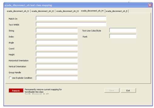
Text Mapping Window
The text-mapping window is to be used for text mapping when the text to be displayed is not included in the data as a separate object. This is true for most attribute based annotation GIS systems. The screen capture below is an example of how a text object can be created for a device class based on the value of an attribute.
Code Lookups
All code lookups to be used in the mapping of the workbook must be specified in their appropriate tab in the workbook. This information is to be entered by the NMS model engineer. Lookups can be database lookups by specifying them as db code lookups in the appropriate CELL file syntax.
Electrical Code Lookups | Contains lookups to be included in the Electrical Layer Objects Cell File. |
Landbase Code Lookups | Contains lookups to be included in the Landbase Layer Objects Cell File. |
Gas Code Lookups | Contains lookups to be included in the Gas Layer Objects Cell File. |
Code Lookups Example

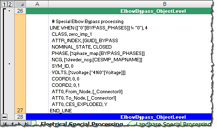
Special Processing Tabs
The Special Processing tabs are arranged according to the cell file they should be included in. A model engineer can use these tabs to add any special CELL file enhancement that cannot be fully generated by the workbook. This includes the addition of nodes such as FBD, FID, SRC, and SND nodes. There are two hooks for each CELL file block generated. One is at the device level, before the end of the first object’s END_LINE or END_POINT). The second is before the cellblock is over, before the END_CELL.
To specify that special processing is required, populate the Special Processing tab in the appropriate class-mapping tab with the display name of the class that requires special processing. The special processing to be used must be specified in a single cell at the appropriate level in the appropriate tab. The level at which this is added is indicated by the name of the special processing section. An example is provided below:
Electrical Special Processing | Special processing for all electrical objects found in sheets, "Devices", "Customer & Service", "Structures", "Annotation" and "Conductors". |
Landbase Code Lookups | Special processing for all land base classes found in sheet "Landbase". |
Gas Special Processing | Special processing for all gas mapping sheets. |
Special Processing Example
Adding an att_[*] Tab to the Model Workbook
When a project specific device type is not already defined in the model workbook, you need to add an att_[*] tab to the workbook. To add the att_[*] tab, complete the following steps.
1. Copy the attribute_template tab.
2. Rename the copied tab using this convention: att_[device/component to be modeled]. For example, street
3. Defined names will need to be placed in the new tab so the Model Config Generator Tool can identify the valid column positions.
4. The columns on the third row of the tab need to contain the defined names.
Note: Reference the other att tabs for examples.
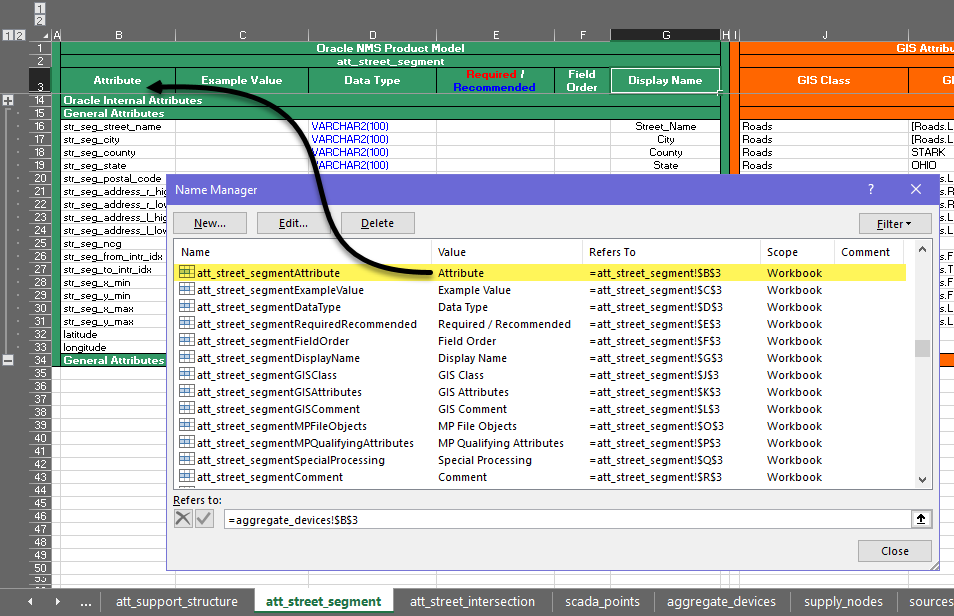
5. From the Excel Formulas ribbon, click Name Manager.
The Name Manager allows you to see and edit all defined names within the workbook.
6. Use the Name Manager to add defined names to each column in the new tab. The naming convention is the tab name concatenated with column name.
Note: Please use other att tabs as template when creating the new defined names. For example, in the screen capture below, the name of the tab is att_street_segment and the first defined name is a concatenation of the tab name and the value in cell B3 (Attribute), which results in a name of att_street_segmentAttribute.
7. Once the defined names have been created, configure the att_ tab as needed.
8. Use the Model Config Generator tool to generate the newly created configuration.
DMS Data Scripts
Project specific configuration needs to be set up during implementation to define which data files generated from the Power Flow Engineering Data Workbook should be loaded to the database during an NMS setup. This is done using a Korn Shell script that lists the DMS data SQL files that need to be loaded to the database and any ancillary configuration that may be needed by a project. The script needs to be project specific since device types present in the field will vary from customer to customer. You can use OPAL‑pf‑setup as a template for getting started; copy it to [project]‑pf‑setup. Lines can be added or removed, as needed.
A project specific version of [project]‑pf‑views.sql also needs to be created to specify configuration related to device limits and load profiles. There isn't a product version of this file since it will be unknown how load profiles will be configured or if temperature based limits will be used by a project; you can, however, use OPAL_schema_pf_views.sql as a template for getting started. Copy and rename it [project]_schema_pf_views.sql and then modify it to meet the project requirements. The main parts that need to be set up are related to the SQL view PF_DEVICE_LIMITS; if temperature based limits are to be used, this view will need to correspond to the number of temperature bands configured. If seasonal views are being used, the configuration will need to be based on the number of seasons configured.
Using the NMS Model Config Generator Tool
The Model Config Generator tool is used to generate model configuration files from a populated Distribution Modeling workbook. The tool is a standalone application that is responsible for reading the modeling workbook, parsing the contents, and generating the desired configuration files.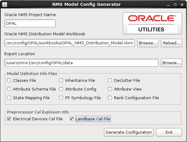
Generating Model Config Files
1. Make the appropriate changes to the Distribution Modeling Workbook.
2. After the changes are made, open the Model Config Generator Tool by using one of the following methods:
a. On Unix, launch the generator using the following script:
$NMS_BASE/bin/model‑config‑generator
b. To run on a Microsoft Windows PC, your first need to zip the NMS_BASE/bin/ModelConfigGenerator directory by running the following command on a Unix terminal:
zip -ry ModelConfigGenerator.zip $NMS_BASE/bin/ModelConfigGenerator
Then move the zip file to the PC, unzip the file, and then navigate to the ModelConfigGenerator directory, and double-click the ModelConfigGenerator.jar file to launch it (assuming Java is installed).
3. Enter the project name, if it is not populated.
4. Browse to the location of the modified Distribution Model Workbook. The tool will read the workbook into memory. Once fully loaded, the Export Location Browse... button will become sensitized.
Note: If a workbook has previously been opened and the path can still be reached, the tool will automatically select this path and load the workbook to expedite the process.
5. Browse to a location where you want to save the configuration files. Once the path is selected, the check boxes for the configuration files will become sensitized.
Note: If an export path has previously been set, and the path can still be reached, the tool will automatically select this location to expedite the process.
6. Select the files you wish to generate.
7. Click the Generate Configuration button. The Model Config Generator Tool will generate the desired configuration files and create reports for any errors encountered.
8. If updates are made to the workbook, click the Reload... button to force a reload of the newly populated data.
Model Build Process for Work Orders
When running the model build process, there can be multiple versions of a given map in the queue of maps to be processed. Map versions must be processed in the order they are submitted to the model build process. If an older version of a map cannot be committed to the model, the system must keep the newer version from being applied.
For single map (version) processing, this is generally not an issue since all the files to be preprocessed are put into one directory; however, when the maps to be processed are provided in model build directories (work orders), the maps that cannot be committed (blocked work orders) will become dependencies on any future map or work order that contains any map from the blocked work order.
Configuration of this feature is optional and will be enabled if you define MP_DIRECTORIES and MP_EXTENSIONS. MP_DIRECTORIES will be a list of directories where your model import files are located (export MP_DIRECTORIES=$NMS_HOME/data/mp). MP_EXTENSIONS will be a list of extensions for import files (export MP_EXTENSIONS=mp). If you have multiple extensions or directories, delimit them with either semicolons (;) or spaces.
To configure the preprocessor to support work_order directories, follow the example in OPAL‑build‑map and make special note of the use of the environment variable _wo_dir, which is set by the [project]‑build‑map script to support work order style multi-partition directory builds. This variable will identify the $OPERATIONS_MODELS/patches sub-directory to write the .mb files to.
Power Flow Engineering Data Workbook
The Power Flow Engineering Data Workbook is an Excel spreadsheet used to gather and manage data required by DMS applications that are not generally available within the GIS and Oracle Utilities Network Management System. The Power Flow Engineering Data Workbook maintains data required to run the Power Flow, Suggested Switching, Optimal Power Flow, Feeder Load Management, Fault Location Analysis, and Fault Location Isolation and Service Restoration applications.
The Power Flow Engineering Data Workbook defines the required data types, the data tables, and the table schemas. An MS Excel spreadsheet is used for each data type and its corresponding data table. Tabs (worksheets) in the Excel spreadsheet contain a description of the data table and the data table columns. Each data worksheet also contains one or more user-editable tables the user fills for each device type in the data model. The user simply edits the enterable table, adding a new row for each unique device type. The engineering data entered into these tabs will be used by the Power Flow Data Generator to generate a set of customer specific engineering data configuration files.
The Power Flow Engineering Data workbook contains tabs for the following device types:
• Equivalent Sources
• Power Transformer Impedance 2 Winding
• Power Transformer Impedance 3 Winding
• Power Transformer Tap Data
• Power Transformer Limits
• Switch Fuse Limits
• Customer Loads
• Customer Hourly Profiles
• Capacitor Banks
• Distributed Energy Resources
• Line Phase Impedances
• Line Sequence Impedances
• Overhead Line Construction
• Overhead Line Conductors
• Overhead Line Framing
Data Files Generated by the Power Flow Data Generator
The Power Flow Data Generator is a stand alone application that is used to generate the desired data files. Below is a list of all files that can be generated with a brief description. Note that [project] indicates that the files generated pertain to a specific project configuration. The file generated should be installed in the respective runtime SQL directory as well as the project configuration SQL directory.
Please note that for new DMS customers, some product SQL files may not run into the database properly until the below data SQL files are added to the project configuration. When initially setting up a new DMS data model, the SQL files below can be generated with no data such that the table schema’s can be run into the database during the initial nms‑setup.
Data file | Description |
|---|---|
~/sql/[project]_powerflowengineeringdata.xlsm | This is the latest checked-in version of the Power Flow Engineering Data workbook, to be used for generating the customer catalog data sql files. |
~/sql/[project]_pf_sources.sql | Contains data pertaining to equivalent source models for the source nodes in the network. |
~/sql/[project]_pf_line_catalog.sql | Impedance details of lines. |
~/sql/[project]_pf_line_limits.sql | Line limit details. |
~/sql/[project]_pf_switches.sql | Contains nominal ampacity data for switches. |
~/sql/[project]_pf_load_data.sql | Contains electrical characteristics of customer loads. |
~/sql/[project]_pf_xfmrtypes.sql | Contains electrical characteristics data for power, step and auto transformers. |
~/sql/[project]_pf_xfmrtaps.sql | Contains electrical characteristics data for power, step and auto transformers. |
~/sql/[project]_pf_xfmrlimits.sql | Contains multiple ratings/limits for branch flows based on seasons for transformers. |
~/sql/[project]_pf_capacitors.sql | Contains electrical characteristics of capacitors and reactors. |
~/sql/[project]_pf_hourly_load_profiles.sql | Contains profiles for load and distributed generation classes. For load profiles this may consist of Residential, Commercial, Industrial. For dist gen if may consist of PV:Sunny, PV:Cloudy. |
~/sql/[project]_pf_dist_gen_data.sql | Contains electrical characteristics of distributed generation devices. |
Using the NMS Power Flow Data Generator Tool
The Power Flow Data Generator tool is a tool used to generate engineering data files from a populated Power Flow Engineering Data workbook. The tool is a standalone application that is responsible for reading the workbook, parsing the contents, and generating the desired configuration files.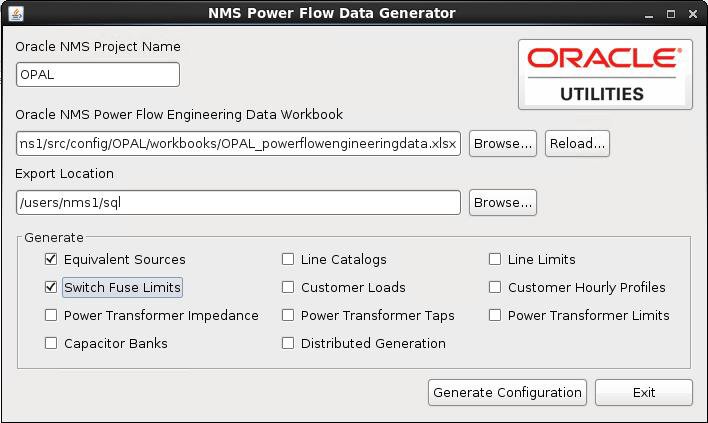
Generating Data Files
1. Make the appropriate changes to the Power Flow Engineering Data workbook.
2. After the changes are made, open the Power Flow Data Generator Tool by using one of the following methods:
a. On Unix, launch the generator with the following script:
$NMS_BASE/bin/powerflow‑data‑generator
b. To run on a Microsoft Windows PC, your first need to zip the NMS_BASE/bin/PowerFlowDataGenerator directory by running the following command on a Unix terminal:
zip -ry PowerFlowDataGenerator.zip $NMS_BASE/bin/PowerFlowDataGenerator
Then move the zip file to the PC, unzip the file, and then navigate to the PowerFlowDataGenerator directory, and double-click the PowerFlowDataGenerator.jar file to launch it (assuming Java is installed).
3. Enter the project name, if it is not populated.
4. Browse to the location of the modified Power Flow Engineering Data Workbook. The tool will read the workbook into memory. Once fully loaded, the Export Location field Browse... button will become sensitized.
Note: If a workbook has previously been opened and the path can still be reached, the tool will automatically select this path and load the workbook to expedite the process.
5. Browse to a location where you want to save the configuration files. Once the path is selected, the configuration file check boxes will become sensitized.
Note: If an export path has previously been set, and the path can still be reached, the tool will automatically select this location to expedite the process..
6. Select the files you wish to generate.
7. Click the Generate Configuration button to generate the configuration files. The Power Flow Data Generator Tool will generate the desired configuration files and create reports for any errors encountered.
8. If updates are made to the workbook, click the Reload... button to force a reload of the newly populated data.
Model and Power Engineering Workbook Locations
An example of these workbooks is included in the Oracle Utilities Network Management System Oracle Power and Light example model and configuration included with every release package. You can find these two workbooks in the $NMS_BASE/OPAL/workbooks directory of the Oracle Utilities Network Management System system.
Load Shed and Restoration
Feeder Load Groups Data Import
The Load Shed/Restoration application is driven by data in the LOAD_GROUPS and LOAD_GROUP_FEEDERS database tables. Those tables can be populated by any mechanism that is suitable for the business process and data sources being used by the project.
Care must be taken when updating the data in these tables because some columns (like last shed/restore times) are updated by the application. Therefore the import process must only update pertinent information in an existing entry. It is also advisable that the update be performed as part of the regular model build process and should be included in the post-build script.
A script (nms‑loadFeederLoadGroups) can be used to populate the tables with data from a CSV file. This script expects the CSV files at the path $OPERATIONS_MODELS/load_groups. The processed CSV files are moved to $OPERATIONS_MODELS/load_groups/parsed_CSVs sub directory and the errors are logged at $OPERATIONS_MODELS/load_groups/log sub directory.
The CSV file format is specified in the LOAD_GROUPS_CONFIG database table. This includes configuring information like number of columns, column positions and whether header present or not
The script can be run with following command line options:
nms‑loadFeederLoadGroups [-clean] [-v] [-debug]
-clean | This will delete all the data in load groups tables and load the groups from CSV file into these tables. |
-v | Turn on verbose output for application. |
-debug | This will turn on debug for assisting with issues in the adapter. If debug is turned on it will by default turn on verbose as well. |
The following assumptions apply:
1. The input CSV files are stored in the $OPERATIONS_MODELS/load_groups directory.
2. Once they have been processed, these files are moved to the $OPERATIONS_MODELS/load_groups/parsed_CSVs directory.
3. For duplicate feeder items within a single input file, the first item read will be used. In some instances theses duplicates may be flagged as errors and placed into the error log file.
4. Log files will be placed in the $OPERATIONS_MODELS/load_groups/logs directory.
5. When adapter is executed any old log files will be moved to the $NMS_HOME/data/load_groups/logs/old_log directory.
Log Files Generated
Load_Groups_Data_Errors_YYYYMMDD_HHMMSS.log: This file will contain any invalid data rows along with an error code from the below list.
• LG-001 # Too many fields
• LG-002 # Too few fields
• LG-003 # Invalid initial priority
• LG-004 # Invalid device type
• LG-005 # Invalid load
To run the import script run during nms‑setup, it should be included in [project]‑pf‑setup.
The OPAL configuration can be examined for examples of how this script is used. In OPAL, the scripts is called from a parent script (LoadOPALFeederLoadGroups).
The LoadOPALFeederLoadGroups script itself is called from OPAL‑pf‑setup and OPAL‑postbuild.
Critical Customer Types
The loadShedAffectedCustomerTypes SRS rule is used to specify the critical customer types for Load Shed and Restoration. Critical customers that are impacted by Feeder Groups is displayed to the operator. The critical customer types included in the counts are specified by this rule. Typical value for rule_value_1 is "egkmt".
If all critical customers should be considered, then leave the rule_value_1 blank.