Symbology
The Viewer displays all model objects and conditions as symbols, either vector symbols or raster symbols. This symbology system is made up of four types of symbols (with the indicated symbol identifier (SIN) range):
• Firm Symbols (30,000 - 99,999)
• Hard Symbols (100 - 2100)
• Soft, Pixmap, or Scalable Vector Graphics Symbols (2100 - 29,999)
Firm and Hard symbols are generally used for linear objects like conductors, roads, and boundaries. Soft, pixmap, and SVG symbols are generally used for devices (switches, transformers, shunt devices, etc.) and other "point" devices.
Firm Symbols
Firm symbols have an eight digit SIN based on the pattern: TTTLSDCC. Each digit defines an aspect of the 1D symbol that is drawn in the Viewer.
• TTT: line thickness. Zero = minimal width (1 pixel). Greater than zero = thickness in world coordinates (feet, meters, etc.)
• L: long dash length
• S: space length
• D: dash pattern
• CC: color code
Firm symbols are indicated by SINs ranging from 30000 to 99999.
L: Long Dash Length. The long dash length is the continuous part of the line between the spaces and short dashes, if any. This digit determines how many pixels the long dash will be. It must be 3 or greater to classify as a firm symbol.
S: Space Length. The space length is the gap between long dashes and short dashes. This digit defines the space’s pixel length as 2*S. An S value of zero results in a solid line even when the dash pattern is greater than zero.
S Value | Length (pixels) |
|---|---|
0 | 0 (No Space) |
1 | 2 |
2 | 4 |
3 | 6 |
4 | 8 |
5 | 10 |
6 | 12 |
7 | 14 |
8 | 16 |
9 | 18 |
D: Dash Pattern. The short dash pattern defines the number and size of short dashes in the line. There can be from zero to three short dashes in each line pattern. The short dashes can be one pixel points, space sized dashes or double space sized dashes.
D Value | Description | Sketch |
|---|---|---|
0 | No short dashes | __________________ |
1 | One point, one pixel | _______ . ________ |
2 | Two points, one pixel each | ______ . . _______ |
3 | Three points, one pixel each | _____ . . . ______ |
4 | One short dash, 1 * S | _______ _ ________ |
5 | Two short dashes, each 1 * S | ______ _ _ _______ |
6 | Three short dashes, each 1 * S | _____ _ _ _ ______ |
7 | One short dash, 2 * S | _______ __ _______ |
8 | Two short dashes, each 2 * S | ______ __ __ _____ |
9 | Three short dashes, each 2 * S | ____ __ __ __ ____ |
CC - Color Code. The line color is specified by a two digit color code.
Code | Name | RGB | Hex | |
|---|---|---|---|---|
00 |  | black | 0/0/0 | #000000 |
01 |  | white | 255/255/255 | #FFFFFF |
02 |  | red | 255/0/0 | #FF0000 |
03 |  | yellow | 255/255/0 | #FFFF00 |
04 |  | green | 0/255/0 | #00FF00 |
05 |  | cyan | 0/255/255 | #00FFFF |
06 |  | blue | 0/0/255 | #0000FF |
07 |  | magenta | 255/0/255 | #FF00FF |
08 |  | orange | 255/165/0 | #FFA500 |
09 |  | pink | 255/192/203 | #FFC0CB |
10 |  | tan | 210/180/140 | #D2B48C |
11 |  | gray | 190/190/190 | #BEBEBE |
12 |  | navy | 0/0/128 | #000080 |
13 |  | brown | 165/42/42 | #A52A2A |
14 |  | purple | 160/32/240 | #A020F0 |
15 |  | salmon | 250/128/114 | #FA8072 |
16 |  | grey10 | 26/26/26 | #1A1A1A |
17 |  | grey20 | 51/51/51 | #333333 |
18 |  | grey30 | 77/77/77 | #4D4D4D |
19 |  | grey40 | 102/102/102 | #666666 |
20 |  | grey50 | 127/127/127 | #7F7F7F |
21 |  | grey60 | 153/153/153 | #999999 |
22 |  | grey70 | 179/179/179 | #B3B3B3 |
23 |  | grey80 | 204/204/204 | #CCCCCC |
24 |  | grey90 | 229/229/229 | #E5E5E5 |
25 | | red1 | 255/0/0 | #FF0000 |
26 |  | red2 | 238/0/0 | #EE0000 |
27 |  | red3 | 205/0/0 | #CD0000 |
28 |  | red4 | 139/0/0 | #8B0000 |
29 |  | limegreen | 50/205/50 | #32CD32 |
30 |  | turquoise | 64/224/208 | #40E0D0 |
31 |  | violet | 238/130/238 | #EE82EE |
32 |  | violetred | 208/32/144 | #D02090 |
33 |  | deeppink | 255/20/147 | #FF1493 |
34 |  | aquamarine | 127/255/212 | #7FFFD4 |
35 |  | khaki | 240/230/140 | #F0E68C |
36 |  | goldenrod | 218/165/32 | #DAA520 |
37 |  | gold | 255/215/0 | #FFD700 |
38 |  | coral | 255/127/80 | #FF7F50 |
39 |  | maroon | 176/48/96 | #B03060 |
40 |  | wheat | 245/222/179 | #F5DEB3 |
41 |  | green3 | 0/205/0 | #00CD00 |
42 |  | green4 | 0/139/0 | #008B00 |
43 |  | coral2 | 238/106/80 | #EE6A50 |
44 |  | yellow1 | 255/255/0 | #FFFF00 |
45 |  | yellow2 | 238/238/0 | #EEEE00 |
46 |  | blue4 | 0/0/139 | #00008B |
47 | not used | |||
48 |  | orange1 | 255/165/0 | #FFA500 |
49 |  | orange2 | 238/154/0 | #EE9A00 |
50 |  | brown4 | 139/35/35 | #8B2323 |
51 |  | magenta1 | 255/0/255 | #FF00FF |
52 |  | magenta3 | 205/0/205 | #CD00CD |
53 |  | steelblue1 | 99/184/255 | #63B8FF |
54 |  | steelblue2 | 92/172/238 | #5CACEE |
55 |  | cyan4 | 0/139/139 | #008B8B |
56 |  | orange4 | 139/90/0 | #8B5A00 |
57 |  | yellow4 | 139/139/0 | #8B8B00 |
58 |  | moccasin | 255/228/181 | #FFE4B5 |
59 |  | light pink | 255/182/193 | #FFB6C1 |
60 |  | deep sky blue | 30/144/255 | #1E90FF |
61 |  | medium aquamarine | 102/205/170 | #66CDAA |
62 |  | snow1 | 255/250/250 | #FFFAFA |
63 |  | blue1 | 0/0/255 | #0000FF |
64 |  | cadet blue | 95/158/160 | #5F9EA0 |
65 |  | dark green | 0/100/0 | #006400 |
66 |  | sea green | 46/139/87 | #2E8B57 |
67 |  | firebrick | 178/34/34 | #B22222 |
68 |  | tomato | 255/99/71 | #FF6347 |
69 |  | light goldenrod | 238/221/130 | #EEDD82 |
70 |  | goldenrod1 | 255/193/37 | #FFC125 |
71 |  | hotpink1 | 255/110/180 | #FF6EB4 |
72 | not used | |||
73 |  | magenta4 | 139/0/139 | #8B008B |
74 |  | chocolate4 | 139/69/19 | #8B4513 |
75 |  | wheat1 | 255/231/186 | #FFE7BA |
76 |  | thistle4 | 139/123/139 | #8B7B8B |
77 |  | steel blue | 70/130/180 | #4682B4 |
78 |  | maroon4 | 139/28/98 | #8B1C62 |
79 |  | coral1 | 255/114/86 | #FF7256 |
80 |  | deeppink1 | 255/20/147 | #FF1493 |
81 |  | laurellee | 2/175/143 | #02AF8F |
82 |  | slate grey | 112/128/144 | #708090 |
83 |  | royal blue | 65/105/225 | #4169E1 |
84 |  | orchid | 218/112/214 | #DA70D6 |
85 |  | dark orange | 255/140/0 | #FF8C00 |
86 | not used | |||
87 | ||||
88 | ||||
89 | ||||
90 | ||||
91 | ||||
92 | ||||
93 | ||||
94 | ||||
95 | ||||
96 | ||||
97 | ||||
98 | ||||
99 |  | eaudenil | 148/218/176 | #94DAB0 |
Hard Symbols
Hard symbols have an eight digit SIN based on the pattern: TTT0LLCC.
• TTT: line thickness. Zero = minimal width (1 pixel). Greater than zero = thickness in world coordinates (feet, meters, and so forth)
• LL: line style
• CC: color code
Hard symbols are indicated by SINs ranging from 100 to 2100; if the SIN is less than 1000, assume a zero before the first digit.
LL: Line style. Choose a line style number based on the desired dash pattern and background color. Dash pattern refers to the alternating number of pixels to draw of specified color and background color. The first number draws the prescribed color, CC; the second number draws the background color; the third number, if any, draws the prescribed color and so on.
Line Style Number | Dash Pattern (pixels) | Background Color |
|---|---|---|
1 | None | Transparent |
11 | 10,1 | Transparent |
12 | 10,1,2,1 | Transparent |
13 | 10,1,2,1,2,1 | Transparent |
14 | 10,1,2,1,2,1,2,1 | Transparent |
15 | 20,10 | Grey30 |
16 | 50,10,10,10 | Grey30 |
17 | 75,10,10,10,10,10,10,10 | Grey30 |
18 | 2,4 | Transparent |
19 | 15,15 | Black |
20 | 15,15 | White |
CC: Color Code. The color codes are the same as those listed under firm symbols. Use the color code to prescribe the foreground color of the dash pattern. The SIN 106 is drawn in the Viewer as a solid blue line. The SIN 1614 is drawn in the Viewer as a dashed line with 50 pixels of purple, 10 pixels of gray30, 10 pixels of purple and 10 pixels of gray30.
1D Width Multiplier
The width multiplier increases the thickness of the firm or hard 1D symbol. Add one or more digits ranging from 1 to 29999 to the base SIN to increase the width of the line drawn on the Viewer. The multiplier increases the width of the line proportionally to the map scale so that the line width increases and decreases with zoom level. If no multiplier is specified or if the multiplier is 1, the line width is always one pixel regardless of zoom level. The actual width of the symbol in pixels is calculated at run time. Note that the results of the multiplier vary with each model.
The width multiplier is added to the beginning or left side of the base SIN starting with the sixth digit. Since hard SINs only have four digits, a zero must be added prior to adding the multiplier. For example, 5001324 is a hard symbol with base SIN 1324. The width multiplier is 50. The extra zero is a placeholder only. The firm symbol 5045733 with base SIN 45733 also has a width multiplier of 50. Divide the symbol id number by 100,000 to determine the width multiplier.
Soft Symbol Definitions
Soft symbols are classified as a point or line. There is no graphic editor for the soft symbols, which are considered to be legacy symbols and customers are encouraged to move to SVG symbols. They are indicated by SINs ranging from 2101 to 29999. Symbol definitions, in the [project]_SYMBOLS.sym file, have a regular pattern consisting of a header and a body. The first line of the header is called the header line and is followed by additional required key attribute lines.
Symbol Header
Header Line
The first header line begins with SH and is then followed by the symbol type, symbol code, and the symbol name:
SH [symbol_type] [symbol_code] [symbol_name]
• symbol_type: a point (P) or a line (L)
• symbol_code: the unique symbol identification number (SIN)
• symbol_name: a text string that names the symbol.
Examples
• Point transformer with SIN 2200:
SH P 2200 xfmr
• Line switch with SIN 2201:
SH L 2201 switch
Anchor Points: A1 and A2
Anchor points determine the default focus point for line and point symbols.
• The focus point for line symbols is the midpoint between two anchor points (A1 and A2).
• The A1 anchor point is the default focus point for point symbols.
Once the drawing coordinates are determined, the symbol is scaled and rotated around its focus point.
A1 [x] [y]
A required record that defines the first anchor point of a line symbol or the only anchor point for a point symbol.
Examples
• Add the default focus point for the transformer:
SH P 2200 xfmr
A1 0 0
• Add the first anchor point for the switch:
SH L 2201 switch
A1 -10 0
A2 [x] [y]
A required record for line symbols that defines their second anchor point. The second anchor point line has the following format.
A2 [x] [y]
• Add the second anchor point for the switch with default focus point (0,0):
SH L 2201 switch
A1 -10 0
A2 10 0
Color Definition
CF [foreground_color_number] [background_color_number]
A required record that defines the colors used for filled objects and double dash lines. The foreground color for filled objects is the line color and the background color is the fill color, but can be configured to use any RGB color.
Examples
• Set the transformer foreground color to 3 (yellow) and background color to 0 (black):
SH P 2200 xfmr
A1 0 0
CF 3 0
• Set the switch foreground color to 1 (white) and background color to 0 (black):
SH L 2201 switch
A1 -10 0
A2 10 0
CF 1 0
Symbol Body [SB]
The first line of the symbol body contains only SB, which denotes that the symbol header has ended and the symbol body definition is beginning. Each subsequent line in the symbol body defines a new aspect of the soft symbol, including color changes, line style changes, draw actions, and movements.
Note: The end of the symbol body is designated by the end of the file or the beginning of a new symbol.
Example
• Transformer:
SH P 2200 xfmr
A1 0 0
CF 3 0
SB
• Switch:
SH L 2201 switch
A1 -10 0
A2 10 0
CF 1 0
SB
The following sections describe valid actions for the symbol body.
PEN Definitions
s [color_number]
Sets the pen to a specified color that cannot be overridden by the Viewer selection color. If a symbol drawn with this pen is selected in the Viewer, it does not blink or change colors.
Example
• Set the switch pen color to black:
SH L 2201 switch
A1 -10 0
A2 10 0
CF 1 0
SB
s 100
SO [color_number]
Sets the pen to a specified color that can be overridden by the Viewer selection color. If a symbol drawn with this pen is selected in the Viewer, it blinks or changes color.
Example
• Set the transformer pen color to black:
SH P 2200 xfmr
A1 0 0
CF 3 0
SB
SO 100
Line
W [width]
Specifies the line width. The results of this value varies for each model.
Example
• Set the switch’s line width to 1:
SH L 2201 switch
A1 -10 0
A2 10 0
CF 1 0
SB
s 100
W 1
L [line_style_number] [length] [length] [length]…
Sets the line style and dash pattern.
Valid values for [line_style_number] are:
• 1 - solid
• 2 - dash; alternate between specified color and transparent
• 3 - double dash; alternate between foreground color and background color
The [length] parameters are optional. They specify the segment lengths for the dash pattern. There can be many [length] parameters, but the last one must be equal to zero.
Example
• Set the switch’s line style to 1 (solid):
SH L 2201 switch
A1 -10 0
A2 10 0
CF 1 0
SB
s 100
W1
L 1
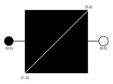
D [x1] [y1] [x2] [y2]
Draws a line symbol between two points (x1, y1) and (x2, y2).
Example
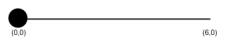
• Draw a solid line with a width of 1 starting at (0,0) ending at (6,0) for the switch:
s 100
W1
L1
D 0.0 0.0 6.0 0.0

CIRCLE
C [x] [y] [radius]
Draws a filled circle with center (x, y) and a specified radius.
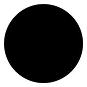
• Draw a black filled circle at (0,0) with radius 2.5:
C 0 0 2.5
• Draw a black filled circle at (0,0) with radius .3:
s 100
W1
L1
D 0.0 0.0 6.0 0.0
C 0.0 0.0 .3
c [x] [y] [radius]
Draws an open circle with center (x, y) and a specified radius.
Example
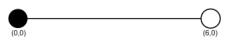
• Draw an open circle with center (6,0) and radius .3:
s 100
W1
L1
D 0.0 0.0 6.0 0.0
C 0.0 0.0 .3
c 6.0 0.0 .3
BOX
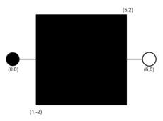
B [x1] [y1] [x2] [y2] [angle]
Draws a filled box between the opposite corners, (x1, y1) and (x2, y2), with the specified angle of rotation.
Example
• Draw a black filled box
s 100
W1
L1
D 0.0 0.0 6.0 0.0
C 0.0 0.0 .3
c 6.0 0.0 .3
B 1.0 -2.0 5.0 2.0 0.0
b [x1] [y1] [x2] [y2] [angle]
Draws an open box between the opposite corners, (x1, y1) and (x2, y2), with the specified angle of rotation.
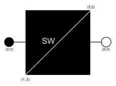
Text
t [height] [width] [vertical_justification] [horizontal_justification]
Sets the height and width of the text at a specified justification. Vertical and horizontal justification have the following values:
• 0 - left or bottom
• 1 - center
• 2 - right or top
The text is drawn with the 'T' record, but the 't' record must be defined first.
Example
Draw a diagonal line with a white pen color; define text attributes with vertical justification = 0 and horizontal justification = 0
s 1
D 1.0 -2.0 5.0 2.0
t 1.0 1.0 0 0
T [x] [y] [angle] "[string]"
Draws the text, "[string]", at (x, y). The text formatting is defined by the 't' record and must be defined prior to the 'T' record.
Example
• Draw the text "SW" at (2,0) with specified text attributes.
T 2.0 0.0 0.0 "SW"
Polygon
M [x] [y]
Defines the first coordinate for a filled polygon. This record must precede the 'P' action.
Example
• Set the pen color to grey70 and define the first point of the polygon for the transformer:
s 22
M 0.0 2.0
P [x] [y]
Defines the next coordinate for a filled polygon. Use this action to specify as many points as necessary. This record follows the ‘M’ action and precedes the ‘F’ action.
Example
• Set the remaining points of the polygon for the transformer:
P -1.7 -1.0
P 1.7 -1.0
F [x] [y]
Defines the last coordinate for a filled polygon. This record follows the ‘P’ action and is the same as the ‘M’ action. It finishes and fills the polygon.
Example
• Finish and fill the polygon. The result is the transformer symbol, xfmr.
F 0.0 2.0

ARC
a [x] [y] [radius] [begin angle] [end angle]
Draws a circular arc at (x, y) with radius from begin angle to end angle.
SCALED OBJECTS (line, circle, box, polygon)
SW [w]
Defines the scaled line width as a percentage of the distance between anchor points.
N
No scale option for lines, circles, boxes or polygons. This must be defined on the same line as the object this record applies to.
Z [A1] or [A2] or [x][y]
Overrides the default focus point of a line, circle, box or polygon. This must be defined on the same line as the scaled object this record applies to.
Hover Text
H "[string]"
Adds a tooltip that is activated when the user’s mouse hovers over the symbol.
Example
• Add "Probable Service Outage" to the probable service outage (PSO) condition symbol.
SH P 4001 probable-service-outage
C#
A1 0 0
CF 1 0
SB
s 4
C 0 0 70
SO 1
B -47.36 47.36 47.36 -47.36 45
s 100
t 80 40 1 1
T 0 0 0 "PSO"
H "Probable Service Outage"
Device Symbols
Here are the base device symbols for the major device class types. Note that these examples are all 3-phase (ABC), nominally closed, and currently closed. Open symbols are green, and off-nominal symbols include a ring around them. Partially open symbols are yellow.
Breaker |  |
|---|---|
Elbow |  |
Disconnect |  |
Fuse |  |
Jumper |  |
Overhead Transformer |  |
Power Transformer |  |
Underground Transformer |  |
Pixmap Symbols
Use $NMS_CONFIG/jconfig/ops/viewer/properties/RasterSymbols.properties to specify the image file to use for a given symbol.
For example:
# This contains a mapping of symbols that should be
# displayed as raster images
# The first file is the normal image. If a second image is listed,
# it is for the selected image. example:
#14042=sym_green_truck.gif,sym_green_truck_sel.gif
#14042=sym_crew.gif
#14043=sym_red_green_truck.gif
#14044=sym_orange_truck.gif
SVG Symbols
SVG symbols offer more complicated device, condition, and outage symbols than the standard .sym symbols, and can be edited and enhanced more easily using standard tools.
Note: The examples in this section use the Inkscape Editor, which is available from inkscape.org.
To use SVG symbols, add your .svg symbol files to your $NMS_CONFIG/jconfig/ops/viewer/images directory and add references to them to the $NMS_CONFIG/jconfig/ops/viewer/properties/SVGSymbols.properties file.
The SVGSymbols.properties file maps the SYMBOLOGY_STATE.symbology_id, CONDITION_RULES.symbol_num, ANALOG_RULES.symbol_num, or QUALITY_RULES.symbol_num database symbol numbers to a .svg symbol file. If you use a selection symbol, the symbol will define the complete visualization of the selected symbol and the viewer.selected_color value will have no impact on the selection symbol.
For example:
4002=Probable_Device_Outage.svg
4004=Real_Device_Outage.svg
14802404=closed_C_fuse.svg
12602700=open_switch.svg
SVG symbols have a default selection capability in the Viewer that highlights the symbol when selected using the VIEWER_GLOBAL_PROPERTIES.inc file's viewer.selected_color StringProperty (configured to be orange in product). You can specify a selection symbol to use for any given symbol by adding a comma and then the selected symbol name to the properties record. For example:
14802404=closed_C_fuse.svg,closed_C_fuse_sel.svg
You can optionally use the nms‑svg‑populate‑properties script to automatically add records to the SVGSymbols.properties file. The .sym files will need to contain a special string in the Identifier metadata of the .sym file (found in the Document Metadata Identifier field in Inkscape):
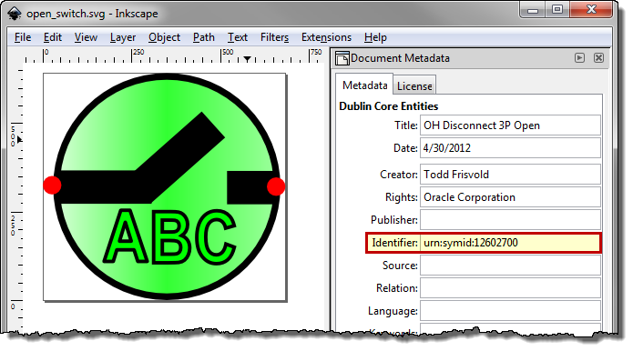
To scan the .svg files in the $NMS_CONFIG/jconfig/ops/viewer/images directory and update the SVGSymbols.properties file, perform the following commands:
$ cd $NMS_CONFIG/jconfig/ops/viewer/images
$ nms‑svg‑populate‑properties
The script will scan the .svg files in the current directory/path, remove any previously auto-generated records in the SVGSymbols.properties file, and add in all new records found in the scan. It will use the Identifier attribute with a string in this format: urn:symid: iiiiiiiiii, where iiiiiiiiii is the symbology Id to associate with this symbol.
The SVG [title] element is used for hover text when the symbol is visualized in the Viewer.
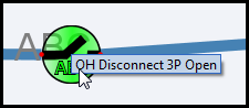
In InkScape, the title is specified in the Document Metadata panel’s Title field:

To specify Anchor Points in the .svg file, place a graphic object and use the Id attribute in the Object Properties. Give the anchor points an id value of AnchorPoint1 or AnchorPoint2:
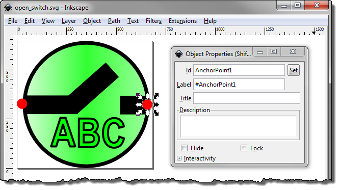
Anchor points can be optionally hidden when drawn in the Viewer by using the Object Fill and Stroke panel and setting the Fill and Stroke Paint Opacity levels to zero. Do not set the Object Properties Hide check box since this will hide the anchor points from the Viewer, which will not know that the anchor points exist.
For condition symbols, SVG symbols work well if you follow these rules:
1. Use AnchorPoint1 and AnchorPoint2 objects in the symbol to define the vertical spacing desired for the symbol.
2. Use a ConditionPoint object to define the symbol placement and the selection point for the condition. This object will define where the symbol will be place in relation to the end of the leader line drawn from the object to the condition symbol. If you do not place a ConditionPoint, unpredictable symbol placement will occur.
3. If AnchorPoint1 and AnchorPoint2 are not defined, the upper left corner of the symbol will be the default location of AnchorPoint1 and lower right corner of the symbol will be the default location of AnchorPoint2.
Adding Text to SVG Symbols with Inkscape
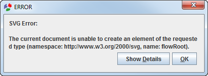
Natively, Inkscape’s text tool adds a non-standard SVG element that is not supported by the Viewer (or any standard SVG viewer). Therefore, when using Inkscape to create SVG symbols with text, you must convert the text with Inkscapes text conversion option.
The following example demonstrates the process of adding text, converting the text to a standard SVG element, and validating the file using the Apache Batik SVG Toolkit’s Squiggle viewer.
Note: The Apache Batik SVG Toolkit is available from the Apache Software Foundation.
Example: Convert Inkscape text to a standard SVG element and validate with Squiggle.
1. Open Inkscape and create a symbol.
2. Add text to the symbol using the Text tool.
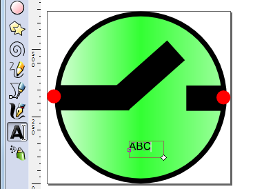
3. Resize and position the text, as needed.
Note: With the non-standard text present, if you save and attempt to open the file with Squiggle, you will receive an error:
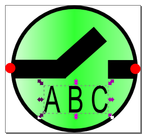
4. With the text selected, select Convert to Text from the Text menu.
5. Save the file.
6. Open the file in Squiggle to validate the SVG is a well-formed XML document.
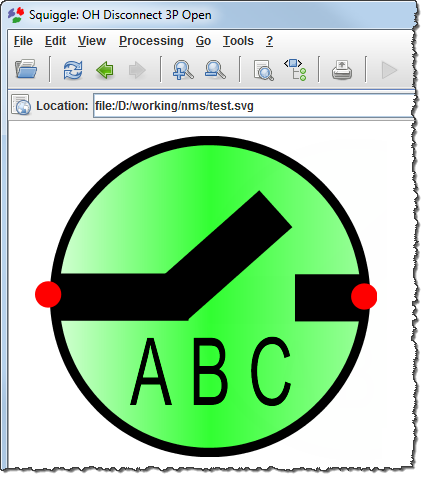
SVG Master Symbol Process
The SVG Master Symbol process generates all required variations (for example, open, closed) of a switchable device symbol from one master symbol definition. The master symbol’s metadata contains the symbol variation variables that are passed to a script that generates the permutations (svg‑symbol‑generator). The process is automated with a script that reads the master symbol directory and generates all symbol permutations (autoSvgGenerator).
autoSvgGenerator Script
The autoSvgGenerator script generates SVG symbols from master symbol files located in the $NMS_CONFIG/jconfig/ops/viewer/images/master directory. The generated .svg files are saved to the $NMS_CONFIG/jconfig/ops/viewer/images/auto-gen directory in sub-directories for each class name (for example, fuses, switches).
Note: the auto-gen directory is deleted before processing the master files.
The master symbol .svg file requires the object IDs set as specified by the svg‑symbol‑generator -help information and an additional text string in the master .svg metadata description attribute with the following format:
AutoConfig:[classNumber]:[className]:[tensDigit][:[normalOpenTensDigit]]
These values are passed to the respective svg‑symbol‑generator command parameters (see “svg‑symbol‑generator Script”).
If the <normallyOpenTensDigit> is specified, autoSvgGenerator executes svg‑symbol‑generator a second time using the [normalOpenTensDigit] value rather than the -tens parameter and, optionally, the ‑normalopen parameter. This will use the inclusion of the symbols object with ObjectID = normal_open_indicator and mixed_status_indicator.
If the -normalopen parameter is not specified on the svg‑symbol‑generator, the ObjectID = normal_open_indicator and mixed_status_indicator will not be included in the resulting symbols.
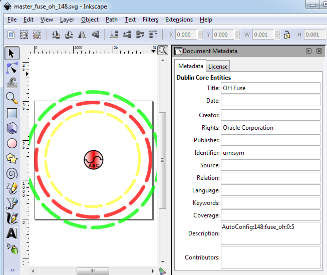
For example, an overhead fuse (class name: fuse_oh/class number: 148) with a normally open tens digit of 5, would be defined as:
<dc:description>AutoConfig:148:fuse_oh:0:5</dc:description>
svg‑symbol‑generator Script
This script will read a single master file and generate the permutations. Format of the command is:
svg‑symbol‑generator
Command parameters:
-classname <name> *REQUIRED*
-classnumber <number> *REQUIRED, integer greater than zero*
-mastersvg <filename> *REQUIRED*
-ganged *Optional*
-tens <digit> *Optional Value 0-9, default: 0*
-closedcolor <number> *Optional Value 000000-ffffff hex,
default: e90000*
-opencolor <number> *Optional Value 000000-ffffff hex,
default: 00ff00*
-abnormalcolor <number> *Optional Value 000000-ffffff hex,
default: ffff00*
-normalopen *Optional
Master Symbol Specification
The master symbol contains all the symbol objects for all permutations of the symbol. Each object that might have its visibility or color manipulated based on phases and status will be given an object ID based on the following:
The following three IDs will place the object based on phase and will color them black if the status is open or closed on all phases and will color them opencolor/closedcolor if the status is mixed
• ID on A phase text: phase_a_letter
• ID on B phase text: phase_b_letter
• ID on C phase text: phase_c_letter
The following three IDs will place the object based on phase and will color them opencolor/closedcolor
• ID on A phase text: phase_a_letter_status
• ID on B phase text: phase_b_letter_status
• ID on C phase text: phase_c_letter_status
The following three IDs will place the object based on phase and will not color them based on status
• ID on A phase text: phase_a_letter_fixed
• ID on B phase text: phase_b_letter_fixed
• ID on C phase text: phase_c_letter_fixed
The following three IDs will place the object based on phase and will not color them based on status
• ID on A phase line: phase_a_line
• ID on B phase line: phase_b_line
• ID on C phase line: phase_c_line
The following three IDs will place the object based on phase and will color them opencolor/closedcolor
• ID on A phase line: phase_a_line_status
• ID on B phase line: phase_b_line_status
• ID on C phase line: phase_c_line_status
The following three IDs will place the object based on phase and will not color them based on status
• ID on A phase filled: phase_a_filled
• ID on B phase filled: phase_b_filled
• ID on C phase filled: phase_c_filled
The following three IDs will place the object based on phase and will color them opencolor/closedcolor
• ID on A phase filled: phase_a_filled_status
• ID on B phase filled: phase_b_filled_status
• ID on C phase filled: phase_c_filled_status
The following ID will color the gradient object based on status
• ID on gradient shaded status shape: status_color_object
The following ID will color the filled object based on status
• ID on simple filled status shape or group: filled_status_color_object
The following ID will color the line object based on status
• ID on simple line status shape or group: line_status_color_object
The following ID will place the object if the status is abnormal
• ID on abnormal ring object: abnormal_object
The following ID will place the object if it is normally open
• ID on normal open object: normal_open_indicator
The following ID will place the object if its status is mixed
• ID on mixed status object: mixed_status_indicator
The following IDs two will identify the anchor points if the device is open
• ID on open anchor point 1 object: anchor_1_if_open
• ID on open anchor point 2 object: anchor_2_if_open
Example
Example Metadata: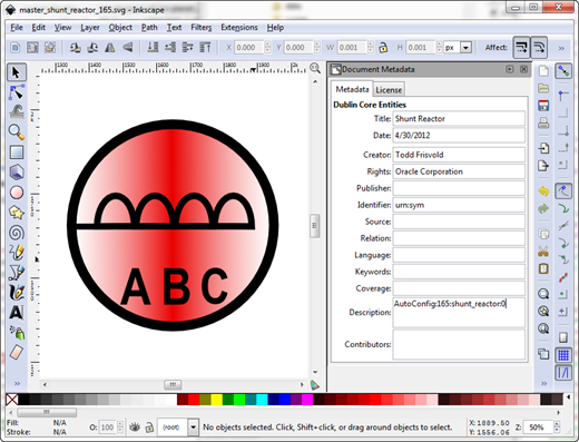
Example: setting the A Phase object ID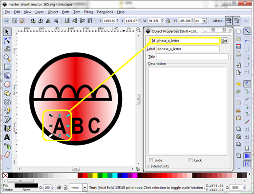
Example running the script:
nmsadmin@nms-vm> cd $NMS_CONFIG/jconfig/ops/viewer/images/master
nmsadmin@nms-vm> ls
master_shunt_reactor_165.svg
nmsadmin@nms-vm> autoSvgGenerator
Info: Generating symbol shunt_reactor number 0
nmsadmin@nms-vm> ls ../auto_gen/shunt_reactor
shunt_reactor_16502100.svg shunt_reactor_16512100.svg
shunt_reactor_16502101.svg shunt_reactor_16512101.svg
shunt_reactor_16502200.svg shunt_reactor_16512200.svg
shunt_reactor_16502202.svg shunt_reactor_16512202.svg
shunt_reactor_16502300.svg shunt_reactor_16512300.svg
shunt_reactor_16502301.svg shunt_reactor_16512301.svg
shunt_reactor_16502302.svg shunt_reactor_16512302.svg
shunt_reactor_16502303.svg shunt_reactor_16512303.svg
shunt_reactor_16502400.svg shunt_reactor_16512400.svg
shunt_reactor_16502404.svg shunt_reactor_16512404.svg
shunt_reactor_16502500.svg shunt_reactor_16512500.svg
shunt_reactor_16502501.svg shunt_reactor_16512501.svg
shunt_reactor_16502504.svg shunt_reactor_16512504.svg
shunt_reactor_16502505.svg shunt_reactor_16512505.svg
shunt_reactor_16502600.svg shunt_reactor_16512600.svg
shunt_reactor_16502602.svg shunt_reactor_16512602.svg
shunt_reactor_16502604.svg shunt_reactor_16512604.svg
shunt_reactor_16502606.svg shunt_reactor_16512606.svg
shunt_reactor_16502700.svg shunt_reactor_16512700.svg
shunt_reactor_16502701.svg shunt_reactor_16512701.svg
shunt_reactor_16502702.svg shunt_reactor_16512702.svg
shunt_reactor_16502703.svg shunt_reactor_16512703.svg
shunt_reactor_16502704.svg shunt_reactor_16512704.svg
shunt_reactor_16502705.svg shunt_reactor_16512705.svg
shunt_reactor_16502706.svg shunt_reactor_16512706.svg
shunt_reactor_16502707.svg shunt_reactor_16512707.svg
Converting SYM Files to SVG
The nms‑sym‑to‑svg script converts .sym files to .svg files. The script will create one .svg file for each .sym symbology preserving the symbology name, ID, anchor points, and all graphic components.
Usage: nms‑sym‑to‑svg [sym_file] [hideanchors] [createselectionsymbols [colornum]] [oversizecanvas [percentage]] [[symId]]
where:
• hideanchors will cause anchor points to be hidden in the resulting SVG files.
• createselectionsymbols will cause the creation of a selection SVG files in addition to normal symbol SVG files using [colornum] as the selection color, typically [colornum] value is 8 for orange, see firm symbol colors (0-99) for color code values.
• oversizecanvas will cause the created svg symbol to have a canvas size [percentage] bigger than the stroke size of the symbol. [percentage] defaults to 10.0 (10%) and must be greater than zero.
• symId will be a symbol ID from the .sym file to display
To convert your sym files, perform the following steps:
1. Run nms‑sym‑to‑svg. The script will output the .svg files in the directory where it is run.
Note: Most projects will want to include the hideanchors option on the command. If you want to retain the legacy selection symbology, run nms‑sym‑to‑svg a second time with the createselectionsymbols option; otherwise your selection symb will use the auto-selection symbology.
2. Move the svg files to the $NMS_CONFIG/jconfig/ops/viewer/images directory
3. Run nms‑svg‑populate‑properties to populate the SVGSymbols.properties file.
Note: you need to be in the $NMS_CONFIG/jconfig/ops/viewer/images directory to successfully run the nms‑svg‑populate‑properties script.
4. Run nms‑install‑config --java to install the new symbols.
SVG Performance Tool
SVG symbols open up many possibilities to symbol creativity however, complex symbols can cause NMS Viewer performance issues too. There are two tools to help the project team to measure SVG symbol rendering performance:
• svgTestSymbolPerformance: Measures a single SVG file for rendering performance at different pixel sizes.
• svgTestSymbolPerformanceReport: Runs svgTestSymbolPerformance and formats output in .csv format for import into a spreadsheet.
Both tools require a display to be available to render the symbols, please specify a DISPLAY location before running the commands.
The svgTestSymbolPerformance script has the following parameters:
Parameter | Description |
-file [filename] | svg file to analyze. Required. |
-min [n] | minimum number of pixels to draw the svg symbol Default = 16 |
-max [n] | maximum number of pixels to draw the svg symbol Default = 1024 |
-steps [n] | number of steps between min and max inclusive to draw the symbol Default = 4 |
-draws [n] | number of draws at each step, Default = 20 |
Example
Enter the following commands:
$ export DISPLAY=host:0.0
$ svgTestSymbolPerformance -file DA_Symbol_14219.svg
The system will output:
File: DA_Symbol_14219.svg Pixels: 16 WallTime: 0.128 CPUTime: 0.11 Draws: 20
File: DA_Symbol_14219.svg Pixels: 352 WallTime: 0.776 CPUTime: 0.54 Draws: 20
File: DA_Symbol_14219.svg Pixels: 688 WallTime: 2.569 CPUTime: 1.14 Draws: 20
File: DA_Symbol_14219.svg Pixels: 1024 WallTime: 6.641 CPUTime: 2.34 Draws: 20
The svgTestSymbolPerformanceReport has the following parameters:
Infile|directory|file.svg
- If Infile is specified, the file is scanned for
svgTestSymbolPerformance report records and reformats them
into .csv format
svgTestSymbolPerformance report records and reformats them
into .csv format
- If directory is specified, the directory is scanned for .svg
files and runs svgTestSymbolPerformance on each of the .svg
files found and then reformats the output into .csv format
files and runs svgTestSymbolPerformance on each of the .svg
files found and then reformats the output into .csv format
- If an .svg is specified, the file is run into
svgTestSymbolPerformance and the output is reformatted
into .csv format
svgTestSymbolPerformance and the output is reformatted
into .csv format
[Optional parameters]
- Any additional parameters are passed to the
svgTestSymbolPerformance process
svgTestSymbolPerformance process
Example
Enter the following commands:
$ export DISPLAY=host:0.0
$ ls
DataRaker_Alarm.svg disconnect_ug_12712707.svg
OPAL_Service_Truck.svg Decomission_30241.svg
Eval_Truck_Made_Safe.svg radio_cap_17202101.svg
der_battery.svg fuse_ug_14902101.svg
xfm_oh_20602707.svg
$ svgTestSymbolPerformanceReport . > report.csv
Processing ./der_battery.svg...
Processing ./OPAL_Service_Truck.svg...
Processing ./Eval_Truck_Made_Safe.svg...
Processing ./DataRaker_Alarm.svg...
Processing ./Decomission_30241.svg...
Processing ./fuse_ug_14902101.svg...
Processing ./radio_cap_17202101.svg...
Processing ./xfm_oh_20602707.svg...
Processing ./disconnect_ug_12712707.svg...
$ cat report.csv
FileName,DrawCount,Pix_16_Wall,Pix_16_Cpu,Pix_352_Wall,Pix_352_Cpu,Pix_688_Wall,Pix_688_Cpu,Pix_1024_Wall,Pix_1024_Cpu
./der_battery.svg,20,0.023,0.02,0.072,0.05,0.065,0.04,0.046,0.02
./OPAL_Service_Truck.svg,20,0.21,0.18,4.166,4.03,5.207,5.04,6.235,5.93
./Eval_Truck_Made_Safe.svg,20,0.069,0.06,0.092,0.08,0.099,0.08,0.111,0.08
./DataRaker_Alarm.svg,20,0.1,0.09,0.277,0.14,0.4,0.12,0.768,0.25
./Decomission_30241.svg,20,0.075,0.07,0.181,0.11,0.279,0.1,0.495,0.18
./fuse_ug_14902101.svg,20,0.061,0.04,0.33,0.16,0.715,0.24,1.491,0.48
./radio_cap_17202101.svg,20,0.063,0.06,0.296,0.15,0.803,0.25,1.48,0.39
./xfm_oh_20602707.svg,20,0.048,0.05,0.248,0.13,0.502,0.17,0.971,0.32
./disconnect_ug_12712707.svg,20,0.072,0.07,0.257,0.14,0.451,0.17,0.806,0.22
When brought into a spreadsheet, the analysis can be interesting: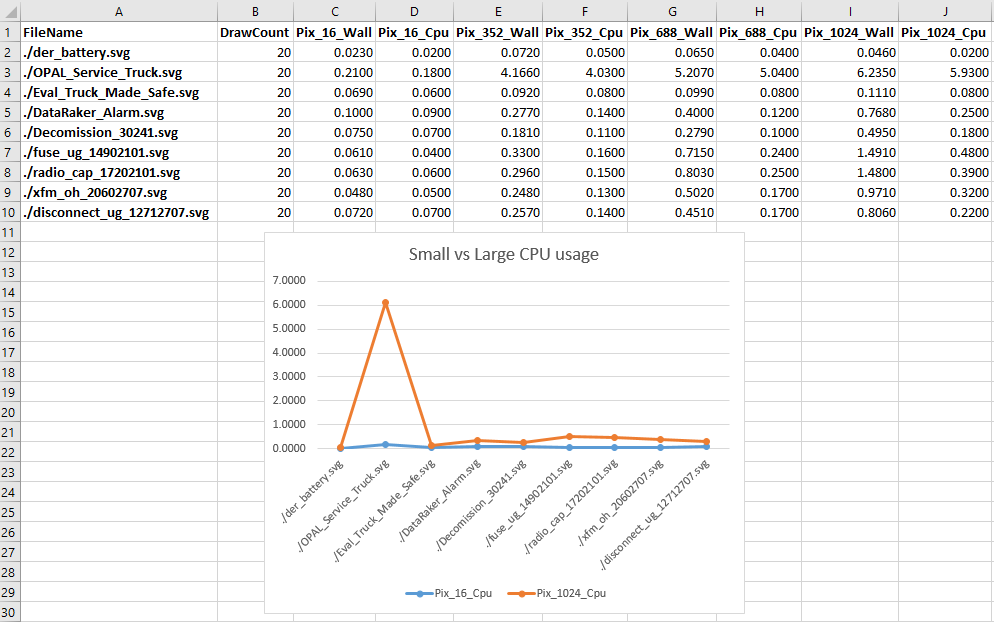
We can clearly see the OPAL_Service_Truck takes a long time to render in larger pixel renderings. This can cause issues with high-resolution displays, such as 4K monitors. Consider simplifying this symbol to minimize any performance impacts.
Updating Symbology
After the symbology file has been updated and the svg files have been installed, the following command will update the java application server:
Action any.publisher* ejb reload_symbology
Any running clients will need to be restarted to pick up the new symbology.
Symbology Mapping
The SYMBOLOGY_STATE Table
The SYMBOLOGY_STATE database table contains the mapping from each device's symbology class, state, and off-nominal status to the symbol used for it.
Column | Description |
|---|---|
context | At this time, always 'RT_TOPOLOGY'. |
symb_state_class | The symbology class, as defined in the DIAGRAM_OBJECTS table. |
state | The bitwise switch status, from 0 to 15, or the conductor energization status, from 0 to 23. The conductor energization statuses are as follows: 0: (Unknown) 1: (Unused) 2: (Ignored) A pending construction or decommissioned conductor. 3: (Energized) A conductor that is energized. 4: (De-Energized) A de-energized conductor. 5: (Suspect Open) and area that is suspected to be deenergized, but the upstream device has not been confirmed to be open. 6: (Parallel) A conductor fed by a set of parallel feeders. 7: (Bidirectional) A conductor fed from both sides, either due to a loop or the direct path of a parallel. 8: (Meshed) A conductor fed by at least one feeder marked with an MID. 9: (Degraded) A partially energized conductor. 10: (Phase A) Phase A is hot. Used in Phase Coloring mode only. 11: (Phase B) Phase B is hot. Used in Phase Coloring mode only. 12: (Phase C) Phase C is hot. Used in Phase Coloring mode only. 13: (Phase AB) Phases AB are hot. Used in Phase Coloring mode only. 14: (Phase AC) Phases AC are hot. Used in Phase Coloring mode only. 15: (Phase BC) Phases BC are hot. Used in Phase Coloring mode only. 16: (Multistate) A combination of Grounded, Faulted, Parallel, etc. on separate phases. 17: (Grounded) The conductor is grounded. 18: (Faulted) The conductor is grounded and energized, or fed by two different phases connected together. 19: (Trace) The conductor is part of the trace results requested by the user. 20: (Isolated) The conductor is in an isolated segment. Isolated segments are areas that are bounded by devices that have been designated as isolated via a Control Tool action and, optionally, any devices that inherit from the "implicit_isolate" base class. 21: (Delegated) The conductor is in a delegated zone. Delegated Zone areas are bounded by devices delegated from a safety document and, optionally, any devices that inherit from the "implicit_delegate" base class. 22: (Secure) The conductor is in an secured segment. Secured segments are areas that are bounded by devices secured from the Control Tool and, optionally, any devices that inherit from the "implicit_secure" base class. 23: (Abnormal Radial) The conductor is fed by only one MID feeder. |
off_nominal_flag | 0/1: Whether the specified state/symbology_id is for an off-nominal position. |
symbology_id | The symbol ID to use. This is either the conductor coloring identifier or the symbol ID found in the symbol file. |
Note: All non-conductor/non-switch objects must use state "0" and off_nominal_flag "0".
The QUALITY_RULES Table
The QUALITY_RULES database table contains the mapping from device class and quality code to the desired symbol or text.
Column | Description |
|---|---|
priority | The priority of the symbol. If more than one symbol matches exactly, the lowest priority rule will be used. |
value | The integer value of the quality. |
string | The string to display, usually a single character. |
description | A description of the quality. |
color | The color of the text to use. |
location | The location (1-9) to use. |
symbol | The symbol ID to use, or -1, if text is to be used; use 0 if no text or symbol should be displayed. |
off_nominal | Unused |
The CONDITION_RULES Table
The CONDITION_RULES database table contains the mapping from device class and condition type to the desired symbol.
Column | Description |
|---|---|
condition | The condition class name, or 'digital' for digital SCADA measurements, 'analog' for analog_rules. |
class | The device class. |
devsymbol_num | The analog or digital attribute number, used only for measurements; 0 otherwise. |
priority | The priority of the symbol. If more than one symbol matches exactly, the lowest priority rule will be used. |
location | The location (1-9) to use. These correspond to upper-left, upper, upper-right, left, center, right, lower-left, lower, lower-right. |
status | The condition status or digital value; -1 for analogs. For truck_location conditions, this is the (TYPE_NUM-1) value from the CREW_TYPES table. |
symbol_num | The symbol to use. Only valid for conditions and digitals; -1 for analogs. |
Consolidating Symbols
If there are multiple conditions of the same type on a device, the symbol will normally stack on the device in the Viewer. For example, if you have two Notes on a device, two Notes symbols will be displayed. If you would rather have multiple occurrences of a condition display as a single symbol with the count adjacent, you can add those condition classes to the condition_aggregate_symbols (in [project]_inheritance.dat).