
Understanding Measuring Component Types
Measuring component types define the most important properties of a measuring component.
Measuring component types define what a measuring component measures (KWH, temperature, etc.), how regularly it measures it, and whether it should be connected to a physical device, or if it's used as a scratchpad measuring component or an aggregator measuring component. Measuring component types also specify how the measuring component's final measurements should be stored, how the measuring component's user-defined values should be calculated, and specific rules governing validation, editing, and estimation (VEE) for measuring components of the type. In addition, measuring component types define display properties and valid attribute values for measuring components belonging to the type.
The following configurable items are available for most measuring component types:
- Value Identifiers: These store the values of UOM, TOU, and SQI that identify the measured amounts for measuring components of this type. Value identifiers specify the quantities stored on the measurement records for measuring components of this type. Please refer to the Measuring Component Type Value Identifiers topic later in this section for more information.
- Valid VEE Groups: These define the VEE groups considered valid for measuring components of this type. Each group supplied here will be available to be selected on measuring components of this type and act as an override to the Fallback VEE Groups.
- Fallback VEE Groups: These define default VEE groups for a specific VEE Group Role that can be used with all measuring components of this type. This alleviates the need to specify the same VEE groups on multiple measuring components of the same type. Changes made to these groups will automatically apply to all measuring components of this type unless they have specified their own VEE groups for that particular VEE Group Role. Each VEE group is designated a VEE group role that indicates when and how the VEE group is used (for initial load, manual override, estimation, etc.).
- Eligible Profile Factors (interval only): These define the profile factors that are considered to be eligible for interval measuring components of this type. One profile factor can be identified as the default. The default profile factor will be automatically selected in system processing when a profile factor is required.
- Valid Profile Factors for Conversion from Scalar to Interval (scalar only): These define the profile factors that are considered to be eligible for scalar measuring components of this type when converting scalar measurements to interval measurements. These profile factors are used to produce a curve of interval data from a scalar value. Without one of these factors defined scalar to interval conversion will use a flat line method (i.e. evenly divide the scalar value across the intervals). One profile factor can be identified as the default. The default profile factor will be automatically selected in system processing when a conversion profile factor is required.
- Valid Scratchpad Measuring Component Types: These define the scratchpad measuring component types considered valid for measuring components of this type.
- Related Statistics Measuring Component Types: These define the measuring component types that will be used to store statistical information about the historical usage of measuring components of this type. Please refer to Configuring Measuring Component Statistics for more information on how this list is used.
-
Display Properties: Defines how measurement data for measuring
components of this type is displayed, including:
- Display Configuration: Details related to how measurements are displayed, including the 360 chart rendering method, number of hours of data to display, the maximum days to search for measurements, the default TOU map used, the TOU by Day Profile factor used, and default measurement condition.
- Event Bar Profiles: The event bar profiles used when displaying measurement data for measuring components of this type. Event bar profiles are defined as values for the 360 View Event Bar Profile extendable lookup.
- Final Values Overlay Profiles: The final values overlay profiles used when displaying measurement data for measuring components of this type. Final values overlay profiles are defined as values for the Final Values Overlay Profile extendable lookup.
- Measurement Conditions Not Shown on Chart: The measurement conditions that should be omitted from rendering onto 360 Degree charts. Measurements whose conditions match these values will be rendered as gaps. For example, many 360 Degree charts use the condition "No Read - System" to represent the lack of a measurement, by adding this condition to this list it a gap will be rendered instead of a line with a 0 quantity measurement and a condition of "No Read - System".
When creating a measuring component type the following options are available:
|
Name |
Details |
Business Object |
|
Interval Channel Type - Physical |
Provides the configuration for a physical interval channel (including interval size). This is recommended for measuring components that measure consumptive usage in interval sizes up to 1 hour. |
D1-IntervalChannelTypePhysical |
|
Interval Channel Type - Scratchpad |
Provides the configuration for a scratchpad interval measuring component. |
D1-IntervalChannelTypeScratchp |
|
Interval Channel Type - Physical Subtractive |
Provides the configuration for a physical subtractive interval channel. In addition to standard interval configuration (including interval size) it also provides additional subtractive specific configuration (e.g. rollover validation, estimate reevaluation, etc). This is recommended for measuring components that measure subtractive usage in interval sizes up to 1 hour. |
D1-IntrvlChanTypPhysSubtractiv |
|
Register Type |
Provides the configuration for a physical register that is manually read (e.g. rollover validation). These can be either consumptive or subtractive but are expected to be read infrequently (e.g. once a month). |
D1-RegisterTypePhysical |
|
Auto-Read Register Type |
Provides the configuration for a physical register that is automatically read. In addition to the standard register configuration (e.g. rollover validation) it also provides details around the schedule of expected readings (e.g. first daily measurement time and expected hours between measurements). These can either be consumptive or subtractive but are expected to be read frequently (e.g. at least once per day). Note: these measuring component types can also be used to model interval data that is received with a large interval size (24 hours and larger). |
D1-AutoReadRegisterType |
|
Aggregator Type |
Provides the configuration for an aggregation measurement. |
D2-AggregatorType |
Refer to Configuring an Out-of-the-box Aggregation for more information about aggregation configuration
Measuring Component Type Value Identifiers
Measuring components are configured to measure specific types of quantities this is defined by the list of value identifiers on the measuring component type. Up to eleven value identifiers can be specified. The primary measured quantity should be identified using the Value Identifier Type of Measurement. An additional ten derived values can be computed based on the primary measurement, these are identified with the Value Identifier Type of Value 01 through Value 10. Each value identifier is constructed of:
- Unit of Measure: The unit of measure for the quantity being recorded. Examples include kilo-watt hours (kWh), kilo-watts (kW), therms, cubic feet (CCF), temperature (Fahrenheit or Celsius), etc. Refer to Understanding Units of Measure for more information.
- Time of Use: Modifiers for a given unit of measure that indicate a period of time during which a quantity has been used, such as On-Peak (meaning during a time when the greatest quantity of some consumable is being used), Off-Peak (meaning during a time when the least amount of some consumable is being used), etc. Refer to Understanding Time of Use for more information.
- Service Quantity Identifiers: Used to further distinguish between measured quantities that have identical UOM/TOU combinations, including situations in which the distinguishing identifier of a UOM is not accurately described as a TOU. Generally, SQI is only used when multiple measuring components measure the same thing, but in different ways. A meter that measures both generation KWH and consumption KWH could use SQIs to differentiate between the two. Refer to Understanding Service Quantity Identifiers for more information.
- Value Derivation Algorithm: Unlike UOM, TOU, and SQI this is not used in the identification of what is measured but rather is used to calculate a derived value based on the primary measurement. An algorithm from the list should be selected that contains the appropriate logic for calculating the derived value. This is applicable for those value identifiers with a Value Identifier Type of Value 01 through Value 10. More information on how derived values are calculated can be found in the Important Measuring Component Type System Events topic in this chapter. For more functional information about derived values please refer to About Final Measurements.
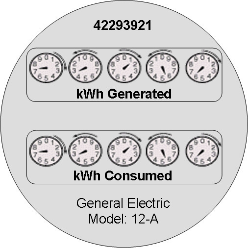
The combination of UOM, TOU and SQI define what a measuring component measures. TOU and SQI are optional, but UOM must be defined for all value identifiers. For example, consider a meter (as illustrated in the image below) with two measuring components, both measuring the same unit of measure (kWh), but each measuring component measures consumption in different time of use (TOU) periods (peak and off-peak).

Another example might be a meter that records both generated KWH and consumed KWH. This meter would be configured to measure both UOM and SQI.
A measurement is recorded each time a measuring component is read. This means that for a meter with two measuring components that is read once a month, two measurements, one for each measuring component, would be recorded each month.
Important Measuring Component Type System Events
The measuring component type supports several business object algorithm system events that relate to calculating the consumption for measuring components of that type:
- Calculate Interval Consumption: receives the interval list and performs any necessary calculations on that interval data to compute consumption. Since interval data is already received as consumption data algorithms for this system event are typically limited to application of the appropriate multipliers. Refer to the algorithm type Calculate Interval Consumption (D1-IN-CNSUMP) as an example.
- Calculate Scalar Consumption: receives information about the scalar reading and calculates the consumption as appropriate. Algorithms for this event typically support calculating the consumption using a stop and start reading or backing into a reading using consumption and a start reading. Much like the interval counterpart it will apply the appropriate multipliers. Refer to algorithm type Calculate Scalar Consumption (D1-SC-CNSUMP) as an example.
- Calculate Subtractive Interval Consumption: receives the interval list and supporting information (e.g. the start reading for the first interval) and either calculates the consumption by subtracting the interval's reading from the prior interval's reading or calculates the reading by adding the current interval's consumption to the prior interval's reading. Refer to algorithm type Calculate Subtractive Interval Consumption (D1-SIN-CNSUM) as an example.
- Condition Mapping: receives the details of a single subtractive interval along with the details for its start reading and computes the applicable final condition and reading condition. This is leveraged solely for subtractive interval measuring component types. Refer to algorithm type Subtractive Interval - Condition Mapping (D1-SIN-CNMAP) as an example.
These system events are typically called from within initial measurement processing during the initial stages of the initial measurement lifecycle (e.g. the Pre VEE status of most initial measurement business objects).
In addition to the measuring component type business object algorithms there is an additional system event provided on measuring component type itself:
- Value Derivation: receives details of an initial measurement and an associated final measurement. Using these inputs it can compute a value derived either from the primary measurement or one of the other derived values. Refer to algorithm type Derive a quantity using a formula (D1-DERIVAQTY) as an example.
Important Measuring Component System Events
The measuring component business object that is associated to a given measuring component type supports a special system event that is used in the periodic estimation process:
- Periodic Estimation: this system event will scan the measuring component's final measurement history to identify missing measurements and create either a To Do, or an estimation initial measurement, or both. More detail about this system event can be found by visiting the following algorithm types: Refer to algorithm type Create Interval IMD and To Do Based Upon Install History (D1-CIITBIH) and Auto-Read Scalar Periodic Estimation (D1-ARSPE) as an example.
Measuring Component Business Object Options
The device business object that is associated to a given device type plays an important role in how a device is processed in a system beyond defining the data associated to that device. Below are a list of business object options that are defined on the device business object and their impact on system processing:
- Estimation Initial Measurement Data BO: Is used to identify the appropriate estimation IMD to create.
- Manual Override IMD BO: Is used to identify the appropriate manual override IMD to create.
- System IMD BO: Is used to identify the appropriate system IMD to create.
- Measuring Component Consumption Function: identifies a function that can be executed from any compatible measuring component 360 Degree zone. Each measuring component can support 0 to many of these functions.
- Interval Initial Measurement Function: identifies a function that can be executed from any compatible initial measurement zone. Each measuring component can support 0 to many of these functions.
More detail about these options can be found by visiting a measuring component business object and inspecting the business object options.