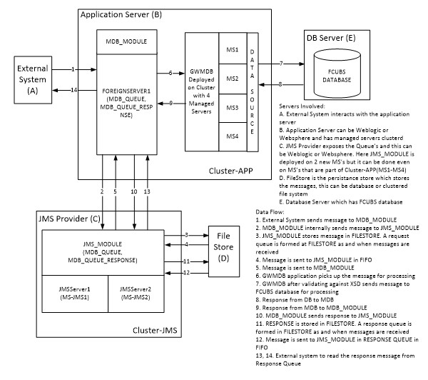
2.3 Components Diagram and Data Flow
Below is the flow diagram which indicates various components that are used and the document explains the steps to create.

Figure 2-3 Components Diagram and Data Flow

Servers Involved -
- External System interacts with the application server.
- The application server can be Weblogic or Websphere and has managed servers clustered.
- JMS provider exposes the Queue and this can be Weblogic or Websphere. Here JMS_MODULE is deployed on 2 new MSs but it can be done even on MSs that are part of Cluster-APP(MS1-MS4).
- FileStore is the persistence store that stores the messages, this can be a database or clustered file system.
- Database Server which has FCUBS database.
Data Flow -
- External System sends a message to MDB_MODULE.
- MDB_MODULE internally sends a message to JMS_MODULE.
- JMS_MODULE stores messages in FILESTORE. A request queue is formed at FILESTORE as and when messages are received.
- The message is sent to JMS_MODULE in FIFO.
- The message is sent to MDB_MODULE.
- GWMDB application picks up the message for processing.
- GWMDB after validating against XSD sends a message to the FCUBS database for processing.
- Response from DB to MDB
- Response from MDB to MDB_MODULE
- MDB_MODULE sends a response to JMS_MODULE.
- RESPONSE is stored in FILESTORE. A response queue is formed in FILESTORE as and when messages are received.
- The message is sent to JMS_MODULE in RESPONSE QUEUE in FIFO.
- The message is sent to JMS_MODULE in RESPONSE QUEUE in FIFO.
Parent topic: Introduction