1 Overview

This topic describes about the overview for Multi Entity feature.

Banks have multiple implementations across geographies that support Multiple entities.

Multi Entity: This feature introduced to Oracle Banking Microservices Architecture products, which enables a single instance of the product (and the underlying Oracle Banking Microservices Architecture platform) to onboard the multiple entities of the bank onto the platform.

As part of the Multi-Entity feature, below are the functionality supported in all Oracle Banking Microservices Architecture products.

  • Creation of "Multi-Entity Admin" user(s)
  • Entity Definition and Maintenance
  • Creation of "Entity Admin" User(s) & regular users
  • Mapping of users (entity admins or regular users) to one or more entities - The users of the application will be central in nature and users can have access to one or more entities.
  • User Entitlement will be local to the entity

1.1 Deployment Diagram

This topic describes about the deployment diagram for Multi-Entity based deployment model.

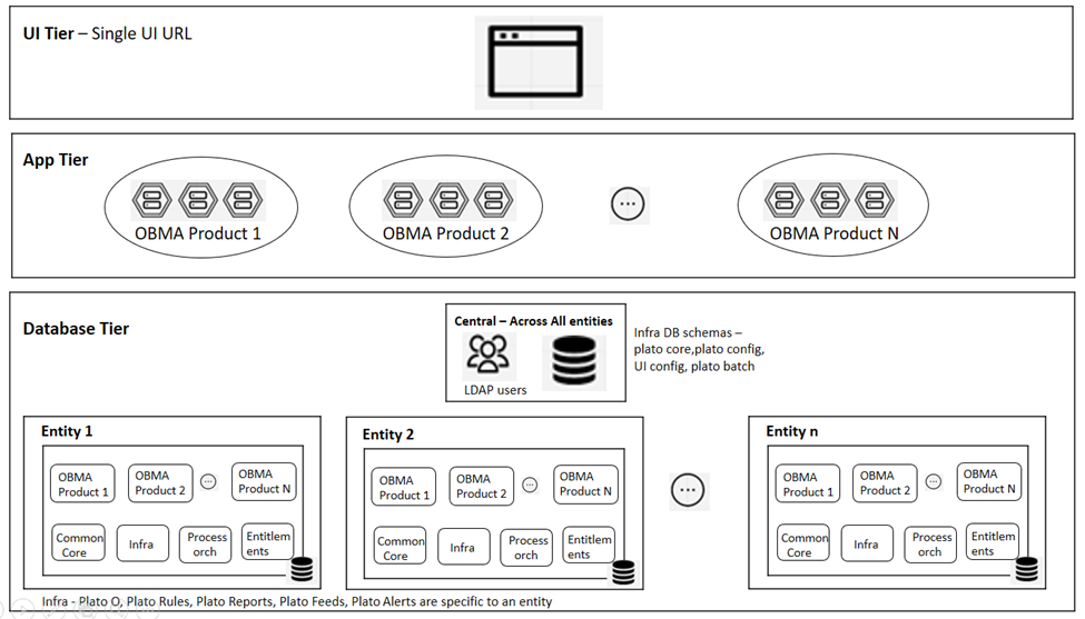
Deployment diagram depicts Multi-Entity based deployment model. Entities based on geographies are considered as an example in the deployment diagram.

UI Tier – UI Domain will be shared across multiple entities for a bank and the same UI URL will be used.

A user can map to one or more entities and a single home entity. During login, the user redirects to the home entity, and an option is provided to switch any of the other associated entities.

Multi Entity admin user has the special access to create/modify new entities in the system.

App Tier – One or more managed servers that host all the microservices are to be deployed for a product.

This includes the below list:

  • Infrastructure services – Plato Infra services (Plato Discovery, Plato API Gateway, Plato Batch, etc…) that are used across all products
  • SMS service – for Role Based Authorization
  • Common Core and Mid-office Common core services - Common domain related services that are used across by one or more products
  • Domain services – micro-services related to Oracle Banking Microservices Architecture products (Oracle Banking Trade Finance Process Management, Oracle Banking Credit Facilities Process Management, Oracle Banking Liquidity Management, Oracle Banking Virtual Account Management, etc...)

Same as UI tier and App tier will be shared across multiple entities. Based on the entity ID provided in the request header, DB schema to the entity will be accessed for all CRUD operations.

Database Tier – The segregation of entities should be done in the DB layer. Separate DB schemas should be defined and used for the entities.

Below are shared across multiple entities:
  • LDAP users
  • few infrastructure related DB schemas - Plato Config, Plato UI config, Plato core, and Plato Batch
Below schemas will NOT be shared and should be specific to an entity:
  • Infra related schemas - Plato O, Plato Rules, Plato Reports, Plato Feeds, and Plato Alerts
  • User entitlements – SMS schema
  • Common core schema
  • Product specific DB schemas (each product will have multiple schemas; ideally 1 schema per microservice/sub-domain)

Banks that have a single entity should follow the same architecture but with "DEFAULT_ENTITY" configured in the system.

1.2 Entity Creation

This topic describes about the various entity creations for Multi-Entity feature.

1.2.1 Default Entity Creation

This topic describes about the default entity creation.

During environment setup, when microservices are deployed, DMLs/DDLs related to “DEFAULT_ENTITY” will be executed through flyway scripts.

Multi entity Admin user should be created as mentioned in Multi Entity Admin User Creation section in Oracle Banking Microservices Platform Foundation Installation Guide.

Note:

Two Multi entity admin users must be created to manage and authorize entity and users in the system.

The bank must pre-determine if the application will be set-up as single or multiple entity system based on the actual implementation requirement. User can directly refer the Single Entity Setup or Multi Entity Setup topics. By default, the system will create an entity with name DEFAULTENTITY and the name is allowed to be modified only once and must be manually controlled.

1.2.2 Single Entity Setup

This topic provides the systematic instruction to setup the single entity for the bank.

  1. Bank can modify the existing DEFAULTENTITY created by system during application set-up.
  2. Before modifying the default entity, DB schemas corresponding to various domains should be identified and corresponding “Data Sources” should be created in Weblogic server.

    Figure 1-2 Data Sources (Filtered - More Columns Exist)


  3. Once the Data Sources are mapped with the corresponding DB schemas and servers, restart the PLATO, CMC, SMS, and other required managed servers.
  4. Check and verify in Eureka to see if all the services are up and running.
1.2.2.1 View Entities

This topic describes the systematic instructions to view and modify the single entity.

The user can configure an entity using the Create Entity screen.
Specify User ID and Password, and login to Home screen with the multi entity admin user.
  1. On Home screen, click Entities. Under Entities, click View Entities.
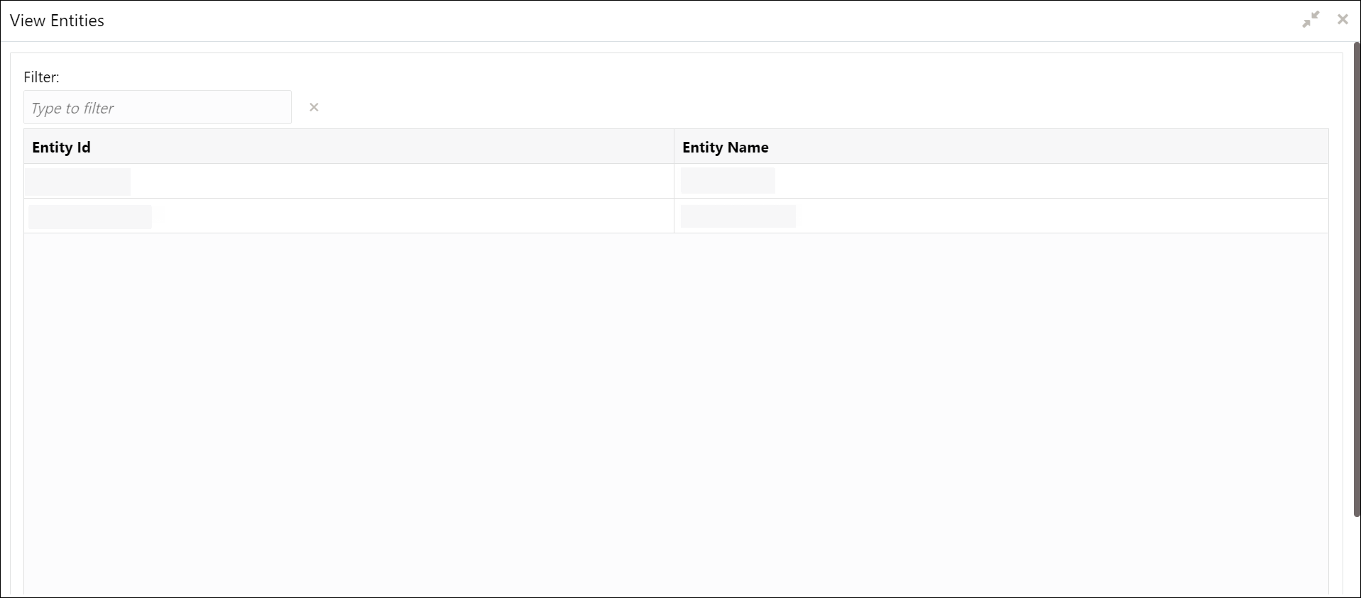
    The View Entities screen displays.
  2. On View Entities screen, view the entity details.

    For more information on fields, refer to the field description table.

    Table 1-1 View Entities – Field Description

    Field Description
    Entity Id Displays the entity Id of the entity.
    Entity Name Displays the name of the entity.
  3. Right-click on DEFAULTENTITY and select the View details.
    The Create Entity screen displays.
  4. On the Create Entity screen, modify the fields.

    Note:

    The fields, which are marked with an asterisk, are mandatory.
    For more information on fields, refer to the field description table.

    Table 1-2 Create Entity – Field Description

    Field Description
    Entity Id Specify the entity Id for the entity.
    Entity Name Specify the name of the entity.
    HO Branch Code Specify the head office branch code of the entity.
    HO Branch Name Specify the head office branch name of the entity.
    HO Branch Address Specify the head office branch address of the entity.
    Host Code Specify the host code.
    Country Select the head office branch country code.
    Current HO Branch Posting Date Select the head office branch current posting date.
    Previous HO Branch Posting Date Select the head office branch previous posting date.
    Next HO Branch Posting Date Select the head office branch next posting date.
    Bank Name Specify the bank name.
    Bank Code Specify the bank code.
    Application Id Click Search icon to view and select the required application ID's from the list.
    JNDI Specify the JNDI for the application ID.

    Note:

    The default entity name value DEFAULTENTITY name can be modified only once and must be manually controlled.
  5. Select the required application id and map it with the new JNDI configured in weblogic.
  6. As part of entity creation through app-shell, JNDI names for each of the applications should be provided.
  7. Click Save. The user can view the confirmation entity details in the View Entities screen.
  8. On Save button, the following common core maintenance data will get created automatically which can be enhanced further after the creation of the entity admin users.
    • Country code
    • Currency definition
    • Language code
    • Bank
    • Branch
    • Branch System date
    • Host code
  9. The following processes will execute in the background.
    • The entity details will be saved in the PLATO_TM_ENTITY table.
    • The JNDIs will be saved in the APPLICATION_LEDGER table.
    • The flyway scripts for all the micro services will get executed in their respective schemas.
    • Once the flyway execution is completed a new role “ENTITY_ADMIN” will be created in the entity. This step will insert scripts into the following tables:
      • SMS_TM_ROLE
      • SMS_TW_ROLE
      • SMS_TM_ROLE_ACTIVITY
      • SMS_TW_ROLE_ACTIVITY
      This role will be assigned to the entity admin user in the user creation step. For more details, refer to Create User topic.
    • The Head Office branch details will be inserted into the CMC_TM_CORE_BRANCH and CMC_TW_CORE_BRANCH tables.
    • The Bank details will be inserted into the CMC_TM_CORE_BANK and CMC_TW_CORE_BANK tables.
    • The System dates will be inserted into the CMC_TM_SYSTEM_DATES and CMC_TW_SYSTEM_DATES tables.

1.2.3 Multi Entity Setup

This topic provides the systematic instruction to setup the multi entity for the bank.

  1. The system by default will have an entity as DEFAULTENTITY. In multi-entity scenario, the bank can rename the DEFAULTENTITY to one of its entities in multi-entity setup. Refer the above section 2.2.2 for steps to modify the default entity.
  2. Before creating new entities through the application, DB schemas corresponding to various domains should be identified and corresponding “Data Sources” should be created in Weblogic server.

    Figure 1-5 Data Sources (Filtered - More Columns Exist)


  3. Once the Data Sources are mapped with the corresponding DB schemas and servers, restart the PLATO, CMC, SMS, and other required managed servers.
  4. Check and verify in Eureka to see if all the services are up and running.
1.2.3.1 Create Entity

This topic describes the systematic instructions to configure a new entity for multi entity admins.

Specify User ID and Password, and login to Home screen with the newly created entity admin user.
  1. On Home screen, click Entities. Under Entities, click Create Entity.
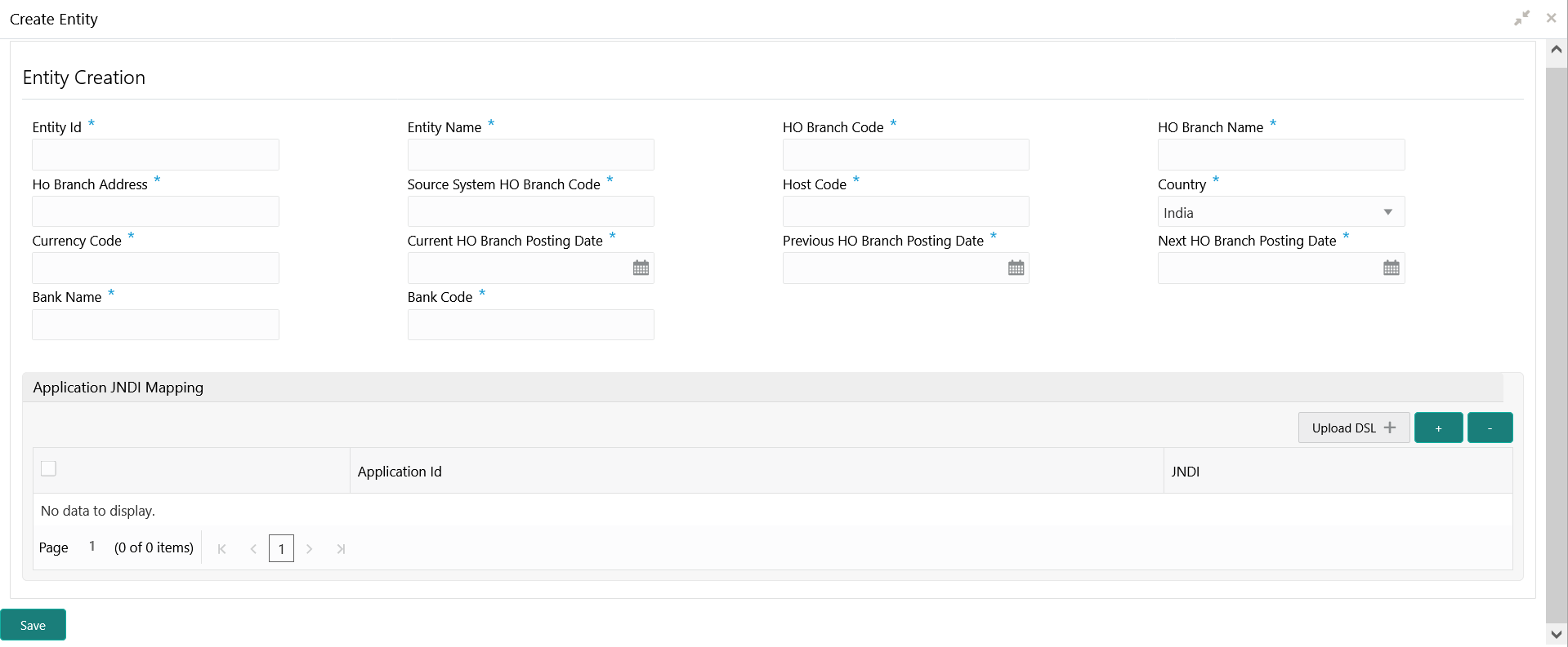
    The Create Entity screen displays.
  2. Specify the fields on Create Entity screen.

    Note:

    The fields, which are marked with an asterisk, are mandatory.
    For more information on fields, refer to the field description table.

    Table 1-3 Create Entity – Field Description

    Field Description
    Entity Id Specify the entity Id for the entity.
    Entity Name Specify the name of the entity.
    HO Branch Code Specify the head office branch code of the entity.
    HO Branch Name Specify the head office branch name of the entity.
    HO Branch Address Specify the head office branch address of the entity.
    Host Code Specify the host code.
    Country Select the head office branch country code.
    Current HO Branch Posting Date Select the head office branch current posting date.
    Previous HO Branch Posting Date Select the head office branch previous posting date.
    Next HO Branch Posting Date Select the head office branch next posting date.
    Bank Name Specify the bank name.
    Bank Code Specify the bank code.
    Application Id Click Search icon to view and select the required application ID's from the list.
    JNDI Specify the JNDI for the application ID.
  3. Click + to add multiple application JNDI mappings.
  4. Click - to remove an application JNDI mapping.
  5. Click Save to save the details.
    The entity is successfully created and can be viewed using the View Entity screen.
  6. Select the required application id and map it with the new JNDI configured in weblogic.
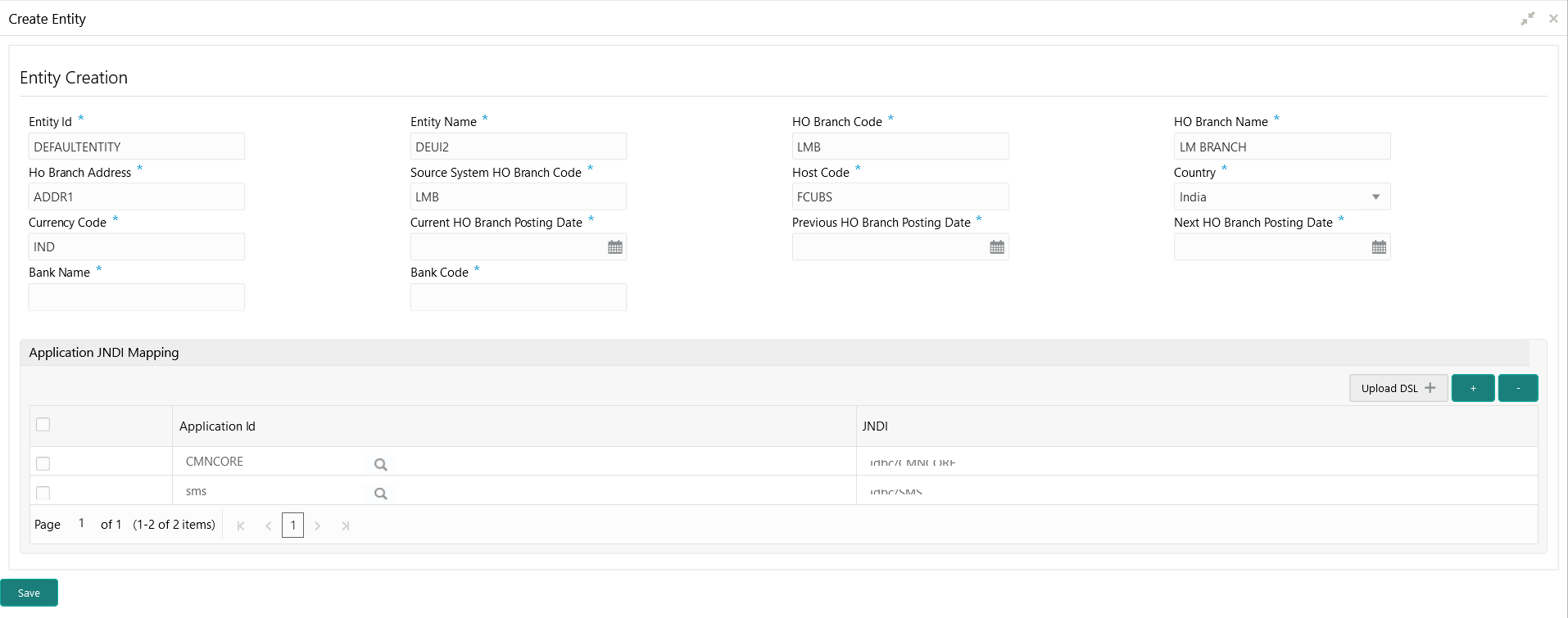
  7. Click Upload DSL button to upload all application ids with JNDI.
    Example DSL Format
    [
        {      
        "appId":"CMNCORE",
        "jndi":"jdbc/CMNCOREKW"
        },
        {
        "appId":"sms",
        "jndi":"jdbc/SMSCOREKW"
        },
        {
        "appId":"SECSRV001",
        "jndi":"jdbc/PLATO_SECURITY"
        },
        {
        "appId":"UICFGSRV001",
        "jndi":"jdbc/PLATO_UI_CONFIG"
        },
        {
        "appId":"LMA",
        "jndi":"jdbc/LMAKW"
        }
    ]
    The Create Entity screan with JNDI Mapping displays.

    Figure 1-7 Create Entity - JNDI Mapping


  8. On Save button, the following common core maintenance data will get created automatically which can be enhanced further after the creation of the entity admin users.
    • Country code
    • Currency definition
    • Language code
    • Bank
    • Branch
    • Branch System date
    • Host code
  9. The following processes will execute in the background.
    • The entity details will be saved in the PLATO_TM_ENTITY table.
    • The JNDIs will be saved in the APPLICATION_LEDGER table.
    • The flyway scripts for all the micro services will get executed in their respective schemas.
    • Once the flyway execution is completed a new role “ENTITY_ADMIN” will be created in the entity. This step will insert scripts into the following tables:
      • SMS_TM_ROLE
      • SMS_TW_ROLE
      • SMS_TM_ROLE_ACTIVITY
      • SMS_TW_ROLE_ACTIVITY
      This role will be assigned to the entity admin user in the user creation step. For more details, refer to Create User topic.
    • The Head Office branch details will be inserted into the CMC_TM_CORE_BRANCH and CMC_TW_CORE_BRANCH tables.
    • The Bank details will be inserted into the CMC_TM_CORE_BANK and CMC_TW_CORE_BANK tables.
    • The System dates will be inserted into the CMC_TM_SYSTEM_DATES and CMC_TW_SYSTEM_DATES tables.
1.2.3.2 View Entities

This topic describes the systematic instructions to view the list of all entities.

The user can configure an entity using the Create Entity screen.
Specify User ID and Password, and login to Home screen.
  1. On Home screen, click Entities. Under Entities, click View Entities.
    The View Entities screen displays.
  2. On View Entities screen, view the entity details.

    For more information on fields, refer to the field description table.

    Table 1-4 View Entities – Field Description

    Field Description
    Entity Id Displays the entity Id of the entity.
    Entity Name Displays the name of the entity.

1.3 Users

This topic describes the information to configure a new users.

Multi entity admins can create entity admins and users.

This topic contains the following subtopics:

1.3.1 Create User

This topic describes the systematic instructions for the multi entity admins to configure a new user.

Specify User ID and Password, and login to Home screen.
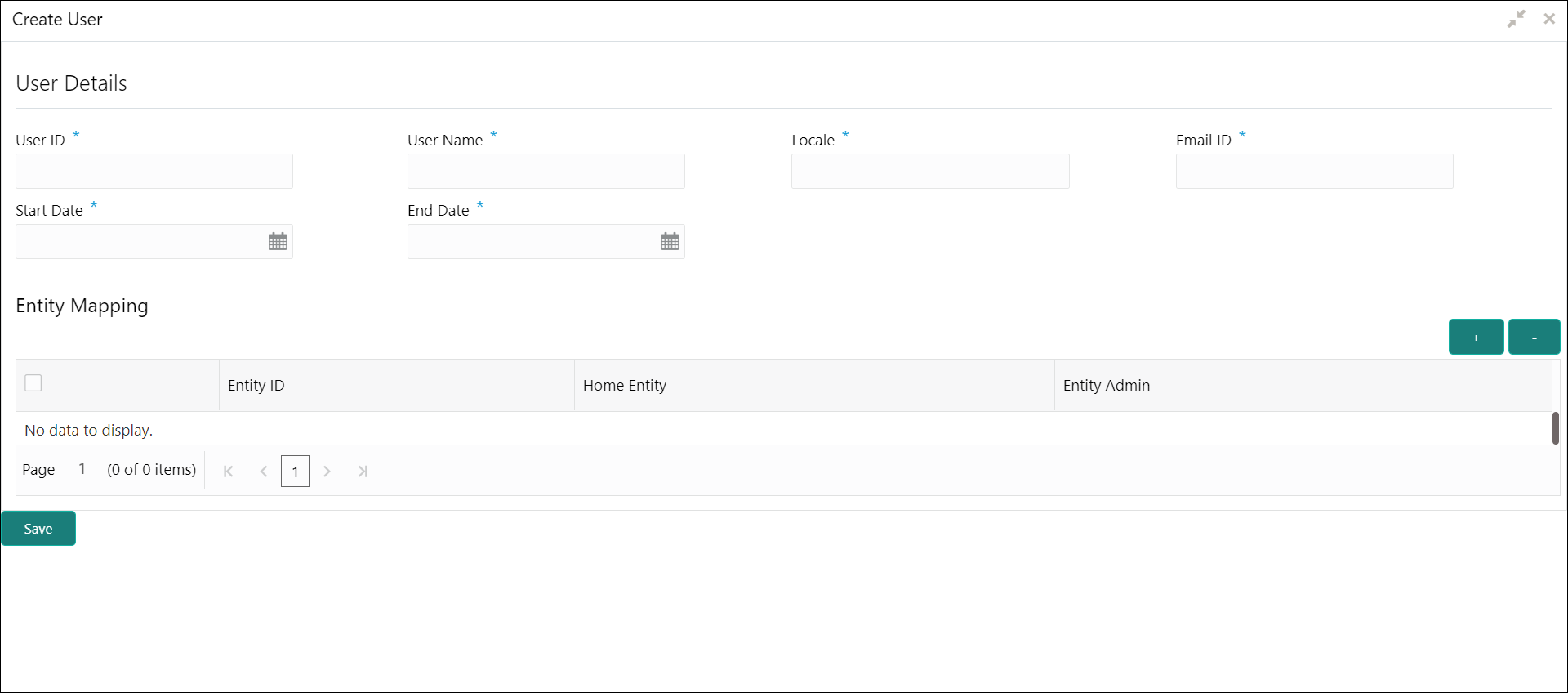
  1. On Home screen, click Users. Under Users, click Create User.
    The Create User screen displays.

    Note:

    In case of a single entity setup, there will be only one mapping to DEFAULTENTITY where as in case of multi-entity setup, a single user can be mapped to multiple entities. At least, one entity must be marked as default home entity. User will login with default home entity in case of multiple entities.
  2. Specify the fields on Create User screen.

    Note:

    The fields, which are marked with an asterisk, are mandatory.
    For more information on fields, refer to the field description table.

    Table 1-5 Create User – Field Description

    Field Description
    User Id Specify the user ID.
    User Name Specify the user name.
    Locale Specify the user locale.
    Email ID Specify the user email ID.
    Start Date Select the user start date.

    Note:

    The start date of the user should greater than the Current HO Branch Posting Date.
    End Date Select the user end date.
    Entity Id Click Search and select the entity to which the user belongs.
    Home Entity Select whether the entity is user home entity.

    Note:

    Only one entity can be selected as Home Entity for a user.
    Entity Admin
    Select whether the user is an entity admin of the entity. Marking a user as Entity Admin will give rights to the user to perform the following actions when logged in to that entity.
    • Modify the details of the users in the entity.
    • Create branches in the entity
    • Create roles in the entity.
    • Assign the roles and branches to the users.
  3. Click + to add a row and provide the required details.
  4. Click Save to save the details.
    The user is successfully created and can be viewed using the View User screen.

    Note:

    Entity Admin option must be enabled to create an administrator user for an entity.
Create LDAP User Account for the new user
  1. Entity admin user will have default access to these core maintenance and security management screen.

    Core Maintenance

    • Currency definition
    • Country code
    • Language code
    • Local Holiday
    • System Dates
    • External Branch Parameters
    • External Bank Parameters
    • Host code

    Security Management

    • Role
    • User
  2. The core maintenances which are automatically created during the creation of an entity can be enhanced further by entity admin user. User can also perform new core maintenance for the new entity. For more information on Core Maintenance, refer to the Common Core User Guide.
Create Normal User
  1. Normal users can be created in Create User screen by disabling Entity Admin toggle.
  2. Unlock and enrich the normal users created by mapping the required user role branches and user applications. Authorize the same. For more information, refer to the Oracle Banking Security Management System User Guide.

1.3.2 View Users

This topic describes the systematic instructions to view the list of configured users.

The user can configure an user using the Create User screen.
Specify User ID and Password, and login to Home screen.
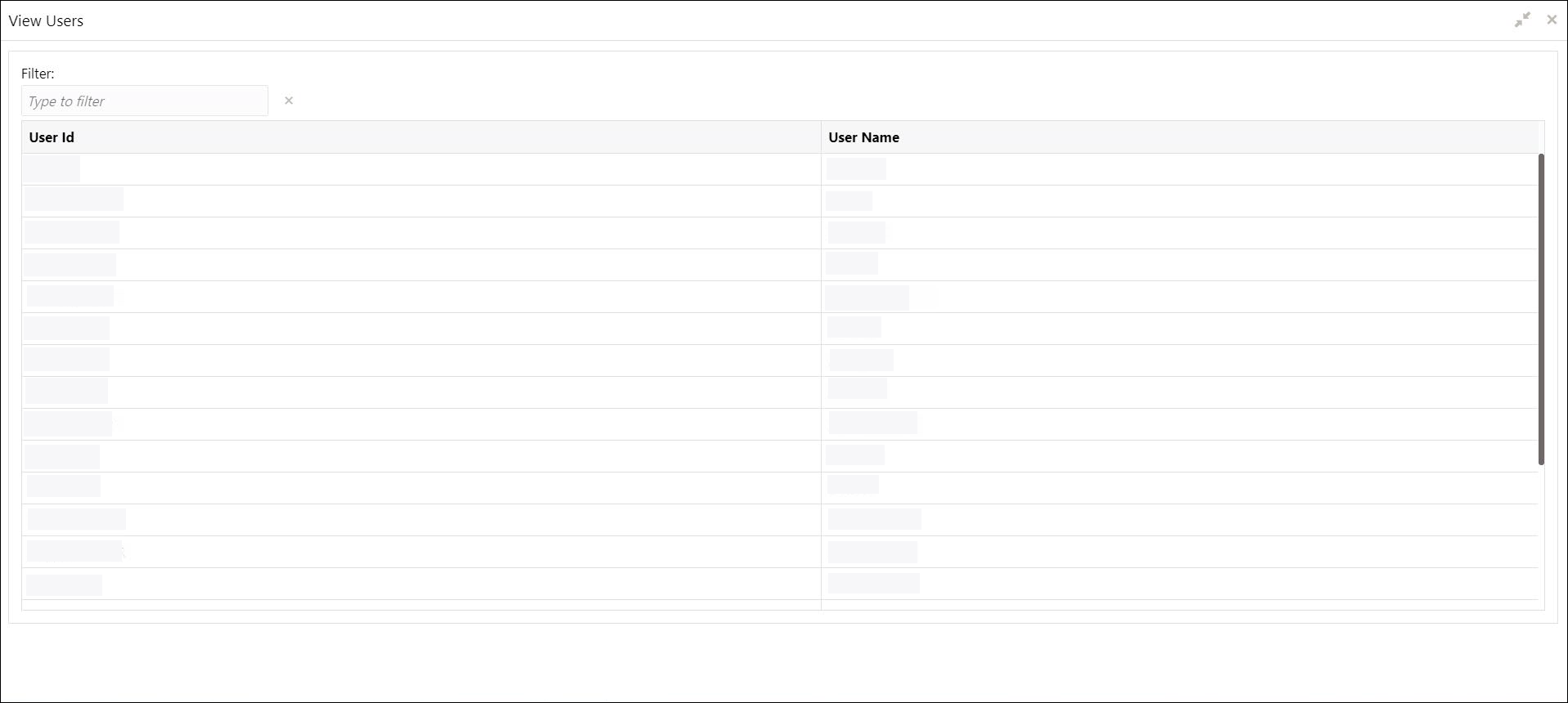
  1. On Home screen, click Users. Under Users, click View Users.
    The View Users screen displays.
  2. Displays the details from View Users screen.

    For more information on fields, refer to the field description table.

    Table 1-6 View Users – Field Description

    Field Description
    User Id Displays the user ID.
    User Name Displays the user name.

1.4 Switch Between Entities

This topic describes about the information to switch between entities.

  1. User can be mapped to one or more entities during the user creation, but only one among the entities should be made as Home Entity.
  2. If a user is mapped to 2 or more entities, then the user is allowed to switch between the entities.
  3. Users can switch between the entities only if :
    1. Same user should be available across the entities.
    2. Same branch should be available across the entities.
    3. User should have proper user role branch mapping done.