5.4.9 Using Network Analysis Tab
About Network Analysis Tab
Note:
To view network graphs in the Network Analysis tab, the User Role must be mapped with the Case Network Tab function (CMNETTB).- Network Analysis Tab is also known as an Ad-hoc network building system.
- Transactions can generate a network on its own, using the search criteria provided by the user via Filters.
- This tab provides the flexibility to draw a graph with one or more business entities as the starting point for the network creation.
- Using Filters feature, the ad-hoc networking, network can be generated from all entities that are part of the case.
Note:
In the Network Analysis tab, all entity searches are run on the business data of the application, and not the case data.Filtering Network Analysis
- Navigate to the Network Analysis tab. Go to the LHS section.
- Enter the following information in the respective fields as described in the
following table.
Table 5-11 Filtering Network Analysis
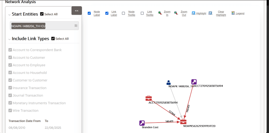
Field Description Start Entities Select entities from the Start Entities list. Or, click Select All to select all entities. Use the start entities list to build the network around entities associated with the event. These entities are considered the starting point of the network.
The following entity types are displayed based on which entities are associated with the events.- Accounts
- Customers
- Households
- External Entity
- Employee
- Correspondent Banks
If the Case has one or more linked events, then use the entity ID(s) from each populated business tab (that is, Account, Customer, Correspondent Bank, Employee, External Entity, and Household) that are not already represented by an events focal ID as a possible starting entity.
If the Case does not have one or more linked events:
Use the entity ID(s) from each populated business tab (that is, Account, Customer, Correspondent Bank, Employee, External Entity and Household) as a starting entity.
The entities are highlighted in the Network Graph.
Include Link Types Select the links from Include Link Types (Account to Customer, Account to Employee,and so on). Or, click Select All to select all links. The Link Types List contains all the valid links, or relationship types, that are identified between two nodes (entities) in the Network Graph. The links are created based on Shared Activity and Known Relationship between two nodes. For more information on Link Types, see Table 18-12.
Selecting a Link Type displays links of the selected type in the graph. For example, the Account to Household link type discovers accounts or household nodes.
Some of the Link Type and Starting Entity combinations may result in no results being returned. For example, selecting only a Household entity in the Entity Name list and selecting Wire Transaction in the Include Link Types list returns no nodes other than the starting Household entity. This is because transactions do not focus on household entities. Table 18-13 provides the Valid Link Types for each node.
The system uses this information to find the most recent information to determine known relationships and shared attributes. For more information, see Table 18-*.
- Click Search. In the Right Hand Side (RHS) pane, the
Network Graph is displayed.
Figure 5-9 Network Analysis

Using Network Graph
This section explains the Network Graph and different components that are displayed on the Right Hand Side (RHS) pane.
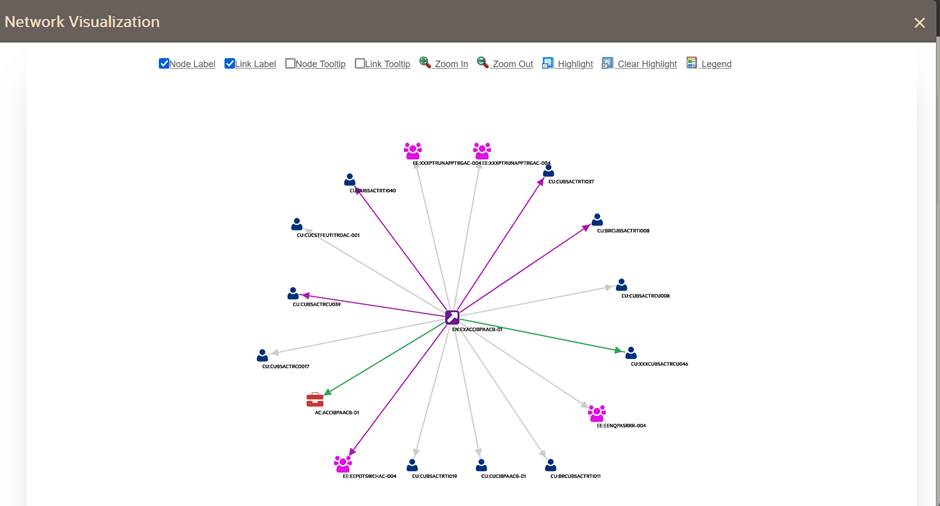
Network graph is the actual graphical representation of the network containing nodes and links. This graph displays only when you initiate a search via Filters.
- Navigate to the Network Analysis tab.
- Go to the LHS section and filter the Network Graph based on
your requirements. The Network Graph is displayed.
Figure 5-10 Network Graph

- Select the following components to view network graphs as described in the
following table.
Note:
By default, Node Label and Link Label options are selected andbased on that network graph is displayed.Table 5-12 Network Graph
Field Description Node Label The Node Label displays in the following format: Node Type, Node ID. Node Type represents the type of entity it is. Node ID represents the identifier of the entity represented by this node. Link Label The middle of each link is labeled with the sum of the amount of all transactional links between the nodes. That is if there is a transaction between the nodes, such as a transfer of funds from one account to another, the total amount of all transactions, across all transactions types, between these nodes are displayed. When the links between nodes are non- transactional links, the Link Label does not display. Node Tooltip A node tooltip displays the following information. - Node Type: The type of entity.
- Node ID: The identifier of the entity represented by this node.
- Total Amount: Sum of the transaction amounts of all links involving this node within the network.
- Incoming Amount: Sum of the transaction amounts of all links going into this node within the network.
- Incoming Count: Count of all transactions where this node is the TO NODE.
- Outgoing Amount: Sum of the transaction amounts of all links going out of this node within the network.
- Outgoing Count: Count of all transactions where this node is the FROM NODE.
- Total Count: Count of all transactions where this node is the TO NODE or FROM NODE.
Link Tooltip A link tooltip displays the following information: - <From Node>
- Known Relationships
Zoom In You can also use your mouse wheel to zoom out. Zoom Out You can also use your mouse wheel to zoom in. Highlight This allows a user to locate nodes and links on the network graph. This window displays two radio buttons - Node and Link. The radio buttons allow the user to switch the context of the search between locating Nodes and Links.- To locate a Node, select the Node radio button.
- To locate a Link, select the Link radio button.
To find the matching nodes, the system should compare "AC123" to all the nodes on the graph (all node records retrieved as a result of the basic filter search should be in the cache). And within each record, use this mapping (for example, Account Internal ID on an Account record) to find the applicable nodes.
Clear Highlight Click this option to clear all visual distinctions made on the graph as a result of using the Highlight feature. Legend This provides a dynamic indicator of the nodes and links that are visible in the graph.
Using Node Menu
The Node menu allows you to view additional information related to the selected node. This menu is displayed when a user right-clicks on a node.
- Account
- Customer
- External Entity
- Household
- Employee
- Correspondent Bank
- Navigate to the RHS menu.
- Go to the required Node and right-click.
The Node menu is displayed. The Node menu displays the following options:
- Collapse: This hides all outgoing links (nodes to which these outgoing links are connecting) from the node being collapsed. The node icon changes when a node is collapsed.
- View Node Details: This opens a window that displays the current information associated with the selected node. You can interact with the main application window that displays the graph while this window is open. At any given time, only one window can be open for a particular node. If you select to view node details of a node for which a Node Details window is already open, an error message is displayed.