Custom Facts
A custom fact is created in the database and populated using the pattern illustrated in the figure below: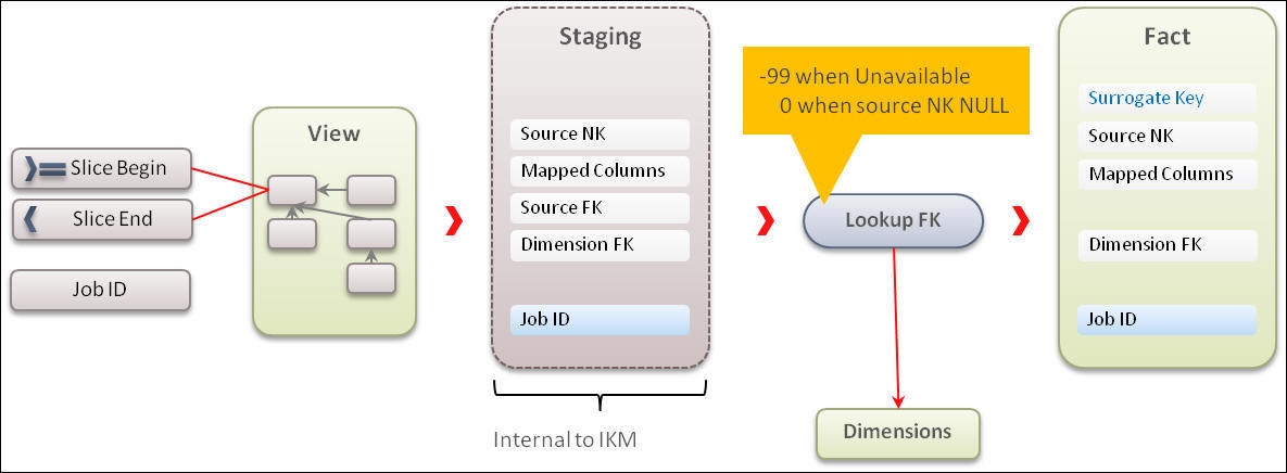
The steps required to create a custom fact and load data into it are as follows:
These steps use an example from Oracle Utilities Customer Care and Billing. The Bill segment Calculation (CM_CF_BSEG_CALC) custom fact is populated with the bill segments line calculation amount.
Each bill generated in Oracle Utilities Customer Care and Billing has multiple bill segments, and each bill segment has multiple calculations with different billing. The CM_CF_BSEG_CALC fact has three dimensions - Service Agreement, Premise, and Service Agreement Status.
The other details are:
• Measure = Calculated Amount for each bill segment’s line
• Natural Key = Bill Segment, Bill Segment Header Sequence
• Source Table = Bill Segment (CI_BSEG), Bill Segment Calculation (CI_BSEG_CALC), Bill Segment Calculation Line (CI_BSEG_CALC_LN)
Creating Fact Tables
This section describes the procedure to create a fact table using an example.
The fact has a primary key, which is the surrogate key column. Use a sequence to generate the values for this key. The fact has a unique key comprising a column from source, the data source indicator. It includes the bill segment details calculation amount for each header in the bill generated in Oracle Utilities Customer Care and Billing.
To create a fact table:
1. Connect to the Oracle Utilities Analytics Warehouse database using SQL Developer.
2. Run the script below to create a fact table in the target schema:
create table dwadm.cm_cf_bseg_calc
(
bseg_calc_key number(15)
,bseg_id number(19)
,bseg_hdr_seq number(5)
,data_source_ind number(6)
,bill_nbr number(30)
,bseg_cre_dttm date
,sa_key number(15)
,prem_key number(15)
,bseg_stat_key number(15)
,currency_cd varchar2(10)
,distribution_cd varchar2(60)
,bseg_calc_amt number(15,2)
,job_nbr number(19)
,update_dttm date
,primary key (bseg_calc_key)
);
3. Run the script below to create a unique composite key for the fact:
create unique index dwadm.cm_f_bseg_calc_uk
on dwadm. cm_cf_bseg_calc( bseg_id,bseg_hdr_seq data_source_ind);
4. Create the sequence used to generate the surrogate key values.
create sequence dwadm.cm_cf_bseg_calc_seq
start with 1
increment by 1;
Importing Fact Tables into Model
After the custom fact is created, import it into the custom model folder (created previously for customization).
To import a fact into a model folder:
1. Login to the Oracle Data Integrator client.
2. On the Designer tab, navigate to the Models > User Customization > <product_name>.
In this example, the product name is ‘CCB’.
In this example, the product name is ‘CCB’.
3. Right-click the product folder and select Open Fact Model. The Open Fact Model window is displayed.
4. On the left pane, click Reverse Engineer.
5. On the right pane, select the Table check box in the Types of objects to reverse-engineer section.
6. Enter “CM_CF_BSEG_CALC” in the Mask field.
7. Click Reverse Engineer at the top-left corner. 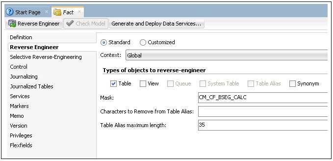
The fact table is reversed in the model.
8. Click Save to save the changes. 
Importing Replicated Tables into Fact Model
To import replicated tables into the fact model:
1. Login to the Oracle Data Integrator client.
2. On the Designer tab, navigate to Models > User Customization > <product name> which has to be customized.
In this example, the product is ‘CCB’.
In this example, the product is ‘CCB’.
3. Right-click and select Open Replication Model. The Open Replication Model window is displayed.
4. On the left pane, click Reverse Engineer.
5. On the right pane, do the following:
a. Select the Table check box in the Types of objects to reverse-engineer section.
b. Enter “CM_CF_BSEG_CALC” in the Mask field.
c. Click Save.
6. On the left pane, click Selective Reverse-Engineering.
7. On the right pane, select the following tables required to load the fact:
• CI_BSEG
• CI_BSEG_CALC
• CI_BSEG_CALC_LN
8. Click Reverse Engineer on the top-left corner.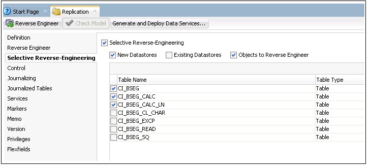
9. Click Save to save the changes.
The replication tables are reversed in the fact model.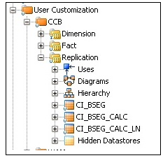
Creating Key Tables in Fact Model
A key table is created to identify the natural key of the entity for incremental loading. It helps to identify specific records for processing instead of scanning the entire replication table.
Ensure the following are taken care while creating a key table in a fact model:
• The resource name of the table is changed to “KEY_#GLOBAl.B1_JOB_ID”.
• The table name can be “KEY_<FACT_NAME>”, but the resource name should be prefixed with the table type followed by the job number.
• Since the table is created at run time, the table name should be suffixed with the job number. It helps in parallel load of the data.
• The key table is created in the model and the flex field is set appropriately.
To create a key table in the fact model:
1. Login to the Oracle Data Integrator client.
2. On the Designer tab, navigate to Models > User Customization > <product_name> > Staging.
3. Right-click Staging, and then select New Datastore from the menu.
4. In the datastore editor, enter “KEY_CM_CF_BSEG_CALC” and “KEY_#GLOBAL.B1_JOB_ID” in the Name and Resource Name fields respectively.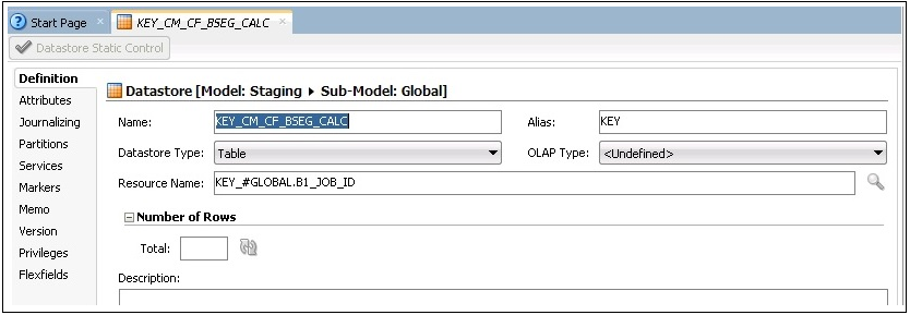
5. Click Flexfields on the left pane.
6. Unselect the Default check boxes for B1 Object Type and B1 Target Entity Name fields respectively.
Enter “TMP” and “CM_CF_BSEG_CALC” in the B1 Object Type and B1 Target Entity Name fields respectively.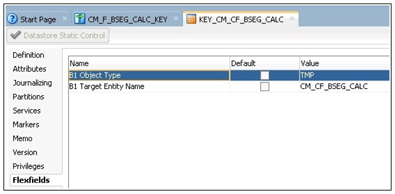
Enter “TMP” and “CM_CF_BSEG_CALC” in the B1 Object Type and B1 Target Entity Name fields respectively.
7. Click the Attributes tab on the left pane.
8. Click + to add columns to the datastore.
Add the columns that are part of the natural key of the fact. Add JOB_NBR in addition to the natural key.
Add the columns that are part of the natural key of the fact. Add JOB_NBR in addition to the natural key.
Note: The data type and length of the columns should match to that of the fact table.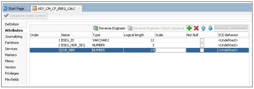
9. Click Save to save the datastore.
Creating Mapping for Key Tables in Fact Model
The key table is created for a fact so that the incremental data for the fact can be filtered based on the key table. The driving tables from the replication schema are included, and columns are created as part of the natural key of the fact. The fact is generated in the Staging schema.
If there are multiple driving tables, the key table data is populated from all the driving tables. Using the “Union” option, distinct data is populated in the key table.
To create a mapping for loading the key table for the fact:
1. Login to the Oracle Data Integrator client.
2. On the Designer tab, navigate to Models > User Customization > <product_name> > Fact > Mapping.
In this example, ‘CCB’ is the product.
In this example, ‘CCB’ is the product.
3. Right-click Mapping and select New Mapping from the menu.
4. In the mapping editor, do the following:
a. Enter “CM_F_BSEG_CALC_KEY” in the Name field.
b. Unselect the Create Empty Dataset check box.
c. Click OK.
5. On the Designer tab, navigate to Models > User Customization > CCB > Replication.
6. Expand the model and drag the tables to the mapping editor.
7. Drag the CI_BSEG_CALC_LN and CI_BSEG driving tables to the mapping editor.
8. Drag the CI_BSEG_CALC_LN table again to the mapping editor.
Since the CI_BSEG driving table does not include the combination of natural key, the table should be joined with CI_BSEG_CALC_LN to get the natural key in the key table.
Since the CI_BSEG driving table does not include the combination of natural key, the table should be joined with CI_BSEG_CALC_LN to get the natural key in the key table.
9. In the Component window, select the JOIN component and enter the name as “JOIN”.
10. Map the CI_BSEG and CI_BSEG_CALC_LN tables as input to the join and specify the join condition in the expression.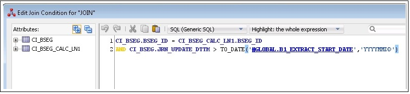
11. Drag the CI_BSEG_CALC table to the mapping editor.
12. Drag the CI_BSEG_CALCL_LN table again to the mapping editor.
Since CI_BSEG_CALC table does not have the combination of natural key of the fact, it should be joined with CI_BSEG_CALC_LN to get the natural key in the key table.
Since CI_BSEG_CALC table does not have the combination of natural key of the fact, it should be joined with CI_BSEG_CALC_LN to get the natural key in the key table.
13. In the Component window, select the JOIN component and enter the name as “JOIN1”.
14. Map the CI_BSEG_CALC and CI_BSEG_CALC_LN table as input to the “JOIN1” and specify the join condition in the expression.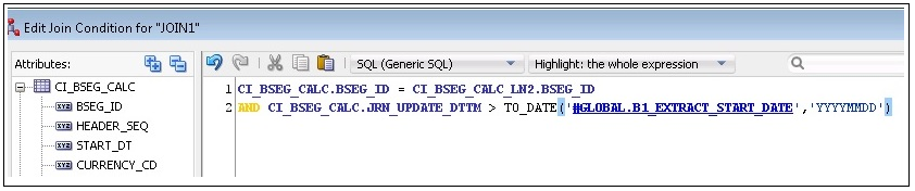
15. Select the components and the SET operator. Drag them to the mapping editor and name the set as “SET_”.
16. Click the SET component on the mapping editor. The Properties window is displayed.
17. Add one more input connections to the SET operator and map them to one of the sources.
For example: INPUT1 > CI_BSEG_CACL_LN, INPUT2 > JOIN, INPUT3 > JOIN1
For example: INPUT1 > CI_BSEG_CACL_LN, INPUT2 > JOIN, INPUT3 > JOIN1
18. On the left pane, click Attributes. Click + to add columns to the SET operator.
19. Add the natural key of the fact and “JRN_SLICING_TS” column to the SET operator.
The column names are displayed. For each INPUT connection, there is an EXPRESSION, and the columns are mapped appropriately.
The column names are displayed. For each INPUT connection, there is an EXPRESSION, and the columns are mapped appropriately.
20. On the Designer, navigate to Models > Framework > Metadata.
21. Drag the B1_JOB_EXEC table to the mapping editor.
22. Drag the FILTER operator from the Component window and map the input of Filter to the output of B1_JOB_EXEC.
23. Add the filter condition as below:
B1_JOB_EXEC.JOB_EXEC_ID = :GLOBAL.B1_JOB_ID
24. Join B1_JOB_EXEC with the output of the SET operator.
This join filters the incremental records only for that slicing period.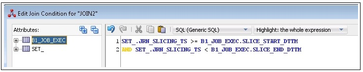
The output of JOIN2 is redirected to distinct only on the natural key of the fact, so that the duplicate keys are loaded into the KEY table.
This join filters the incremental records only for that slicing period.
The output of JOIN2 is redirected to distinct only on the natural key of the fact, so that the duplicate keys are loaded into the KEY table.
25. Drag the KEY table from the model and map the natural key from DISTINCT operator to the Target table.
26. Select the key columns from the KEY table in the Properties window.
27. In the Attributes section, select the respective KEY check box for all the columns that are part of the natural key.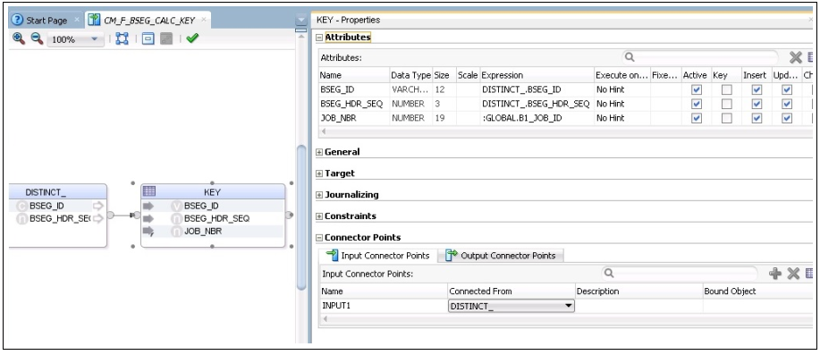
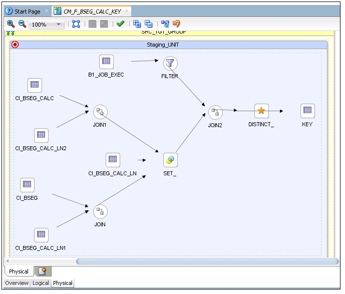
The figure below shows the logical mapping of the tables.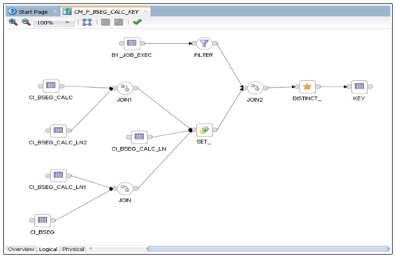
The figure below shows the logical mapping of the tables.
28. On the Physical tab, select the context and save the mapping so that the physical mapping diagram is visible.
In this example, select “CCB7”.
In this example, select “CCB7”.
29. Click the target table and open the Properties window. Do the following:
a. Select “IKM BI Direct load” from the Integration Knowledge Module drop-down list.
b. Modify the “DML_OPERATION” option to “INSERT”.
30. Click Save to save the mapping.
Creating Loading Views in Fact Model
The fact loading view is created in the replication model. Since the table is created at run time, the table name is suffixed with the job number. It helps in the parallel data load.
To create a loading view in the fact model:
1. Login to the Oracle Data Integration client.
2. On the Designer tab, navigate to Models > User Customization > <product_name> > Replication.
In this example, ‘CCB’ is the product.
In this example, ‘CCB’ is the product.
3. Right-click Replication and select New Datastore from the menu.
4. On the datastore editor, enter the view name “CM_CF_BSEG_CALC_VW” for the name.
5. Navigate to Attributes tab.
6. Click + to add columns to the datastore. Add all columns from the fact table except the dimension keys.
7. In the dimension keys, replace “KEY” with “FK”.
The natural key of the dimension in view is needed to lookup the dimension and populate the dimension key in fact. If the dimension’s natural key has more than one column, then the view has the dimension’s natural key. The naming convention of the keys is FK1, FK2, etc.
The natural key of the dimension in view is needed to lookup the dimension and populate the dimension key in fact. If the dimension’s natural key has more than one column, then the view has the dimension’s natural key. The naming convention of the keys is FK1, FK2, etc.
Note: The data type and length of the columns should match with that of the fact.
8. In addition to the above columns, add IND_UPDATE and UPDATE_DTTM columns. The data types of these columns are CHAR(1) and DATE respectively.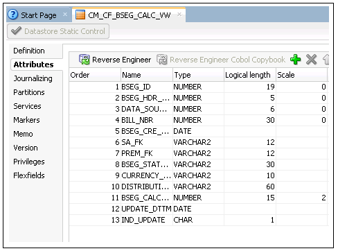
9. Click Save to save the datastore.
Creating Mapping to Loading Views for Fact Model
The loading view for a fact is created to load the data into the fact. The loading view is joined with the KEY table on natural key, so that the data in that slicing period is loaded. The view is generated in the Replication schema.
To create a mapping to generate the loading view:
1. On the Oracle Data Integrator client, navigate to Models > User Customization > <product_name>.
In this example, ‘CCB’ is the product.
In this example, ‘CCB’ is the product.
2. Create a new folder “Replication” and expand it.
3. Right-click Mapping and select New Mapping from the menu.
4. In the mapping editor, do the following:
a. Enter “CM_CF_BSEG_CALC_VW” in the Name field.
b. Unselect the Create Empty Dataset check box.
5. Navigate to Models > User Customization > CCB > Replication.
6. Drag the tables from the model, and the CI_BSEG_CAL_LN and CI_BSEG replication tables to the mapping editor.
7. Select the JOIN component from the Component window and name it as “JOIN”.
8. Map the CI_BSEG and CI_BSEG_CALC_LN tables as input to the join and specify the join condition in the expression.
9. Drag the table CI_BSEG_CALC to the mapping editor.
10. Select the JOIN component from the Component window and name it as “JOIN1”.
11. Map the CI_BSEG_CALC and output of JOIN as input to the join component “JOIN1” and specify the join condition in the expression.
12. Drag the View datastore from the model and map the columns from the replication tables as per the logic to populate the columns. 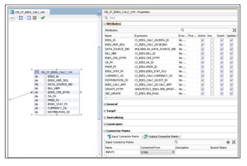
UPDATE_DTTM should be populated as Greatest of JRN_UPDATE_DTTM or JRN_EFF_START_DTTM from all the replication tables. It is populated so that the latest Dimension key of the SCD2 dimension is populated.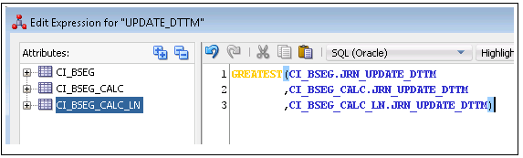
DATA_SOURCE_IND is populated from the B1_DATA_SOURCE_IND variable from Global objects.
UPDATE_DTTM should be populated as Greatest of JRN_UPDATE_DTTM or JRN_EFF_START_DTTM from all the replication tables. It is populated so that the latest Dimension key of the SCD2 dimension is populated.
DATA_SOURCE_IND is populated from the B1_DATA_SOURCE_IND variable from Global objects.
13. Map the primary driver table’s JRN_FLAG to IND_UPDATE.
The figure below shows the logical mapping.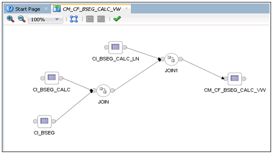
The figure below shows the logical mapping.
14. Navigate to the Physical tab and select Context.
15. Save the mapping so the physical mapping diagram is visible.
In this example, select “CCB7”.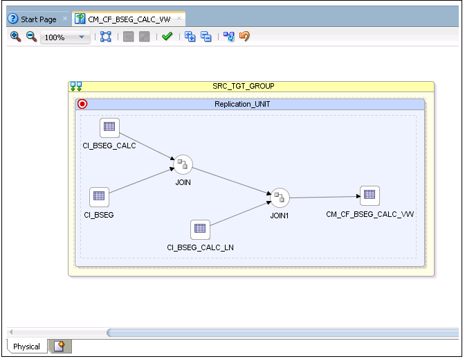
In this example, select “CCB7”.
16. Click the target table. On the Properties window select “IKM BI View Generator” from the Integration Knowledge Module drop-down list.
17. Click Save to save the mapping.
18. Create a package with the same name as that of the view name.
19. Drag and drop the global variable “B1_DATA_SOURCE_IND”. Drag the mapping and join the steps. 
20. Click Save to save the package.
21. Regenerate the scenario for the package. During regeneration, unselect the Startup Variable check box.
22. Run the scenario in Context so that the view is created in the database.
Creating Aggregate Tables in Fact Model
An aggregate table is created by the scheduling process during the execution of a fact job. It is created to optimize the parallel execution of multiple slices of the same entity load.
The table name starts with ‘AGG’ and is suffixed with the job number. The table structure should be present in a fact model under the Staging folder. The table name can vary (such as AGG_<FACT_NAME>), but the resource name should be “AGG_#GLOBAL.B1_JOB_ID”.
The aggregate table is created based on the flex field. The table structure is similar to the target table structure, including a few more columns. There should be an IND_UPDATE column in the table, in addition to the columns used in the mapping. The table should also include an UPDATE_DTTM column which stores the greatest effective start date of the record.
To create an aggregate table in the fact model:
1. On the Oracle Data Integrator client, navigate to Models > User Customization > <product_name> > Staging.
2. Right-click the model and select New Datastore from the menu.
Note: Create a staging model if it does not exist.
3. On the Datastore editor, do the following:
a. Enter “AGG_CM_CF_BSEG_CALC” in the Name field.
b. Enter “AGG_#GLOBAL.B1_JOB_ID” in the Resource Name field.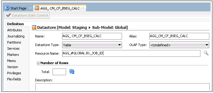
4. Click Flexfields on the left pane.
5. Unselect the Default check box. Enter “TMP” and “CM_CF_BSEG_CALC” in the B1 Object Type and B1 Target Entity Name fields respectively. 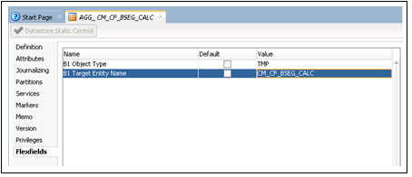
6. Click Attributes on the left pane.
7. Click + to add the required columns to the datastore.
8. Add all columns from the fact table except the dimension keys.
9. In the dimension keys, replace “KEY” with “FK”.
The natural key of the dimension in view is needed to lookup the dimension and populate the dimension key in fact. If the dimension's natural key has more than one column, then the view has the dimension's natural key. The naming convention of the keys is FK1, FK2, etc.
The natural key of the dimension in view is needed to lookup the dimension and populate the dimension key in fact. If the dimension's natural key has more than one column, then the view has the dimension's natural key. The naming convention of the keys is FK1, FK2, etc.
Note: The data type and length of the columns should match with that of the fact.
10. In addition to the above columns, add IND_UPDATE and UPDATE_DTTM columns.
The data types of these columns are CHAR(1) and DATE respectively.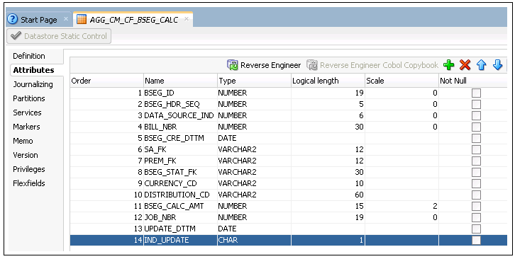
The data types of these columns are CHAR(1) and DATE respectively.
11. Click Save to save the datastore.
Creating Mapping to Load Aggregate Tables in Fact Model
After creating an aggregate table, the data is loaded using the KEY table and loading the view created for the fact.
To create a mapping to load an aggregate table in the fact model:
1. Login to the Oracle Data Integrator client.
2. Navigate to Projects > User Customization > <product name> > Mapping.
In this example, ‘CCB’ is the product.
In this example, ‘CCB’ is the product.
3. Right-click Mapping and select New Mapping from the menu.
4. On the mapping editor, enter the mapping name in the Name field. Unselect the Create Empty Dataset check box.
5. On the designer, navigate to Models > User Customization > CCB > Staging.
6. Drag the KEY_CM_CF_BSEG_CALC table from the model to the mapping editor.
7. On the designer, navigate to Models > User Customization > CCB > Replication.
8. Drag the CM_CF_BSEG_CALC_VW view from the model to the mapping editor.
9. Select the JOIN component from the Component window. Enter “JOIN” in the Name field.
10. Map the KEY table and loading view as input to the join and specify the join condition in the expression.
11. Drag the AGGREGATE component in the Components window and drop it onto the mapping editor.
12. Map the output of the join to the AGGREGATE component.
13. In the AGGREGATE component Properties window, click + in the Attributes section to add columns.
Note: Ensure that the column names should match with those of the AGGREGATE table.
14. Map all columns from the Loading view and KEY table as applicable. 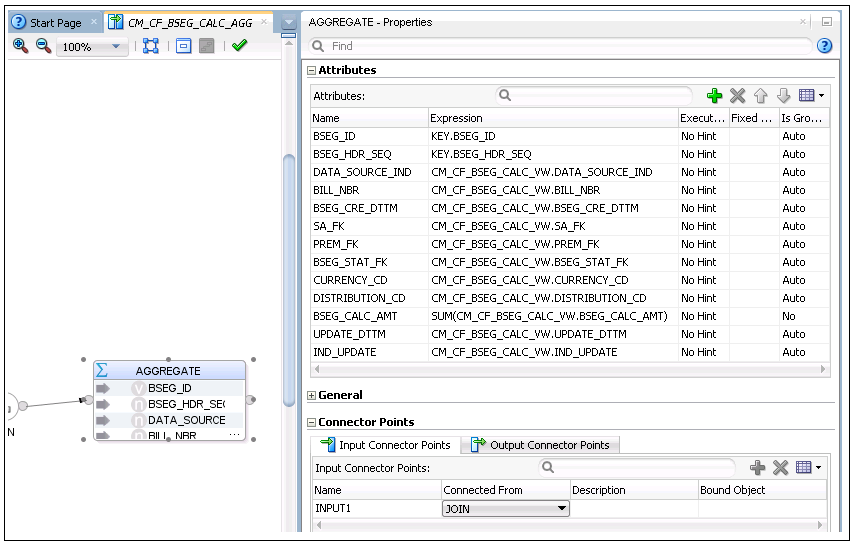
15. On the designer, navigate to Models > User Customization > CCB > Staging.
16. Drag the AGG_CM_CF_BSEG_CALC aggregate table from the model.
17. Map the output of the AGGREGATE component to the input of the AGG table.
18. Map all columns of the AGGREGTE table.
19. Select the KEY columns in the table. Select the respective KEY check box for those columns that are part of the natural key.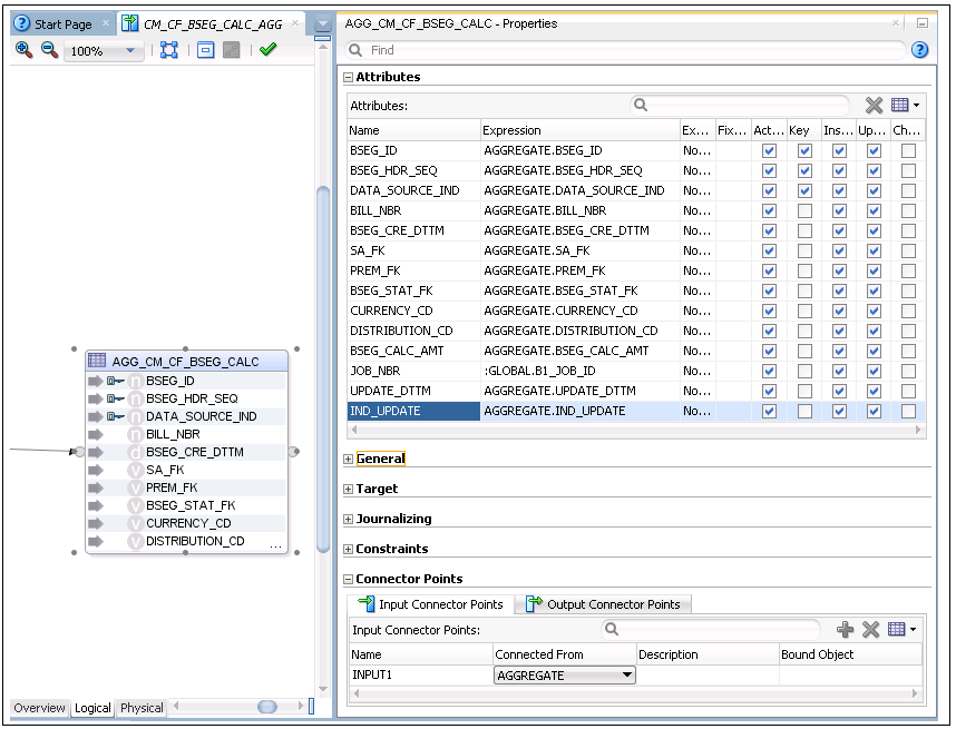
20. The logical mapping is complete as shown in the figure below. 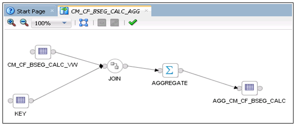
21. On the designer, navigate to the Physical tab. Select the Context and Save the mapping so that the physical mapping diagram is visible. In this example, select “CCB7”. 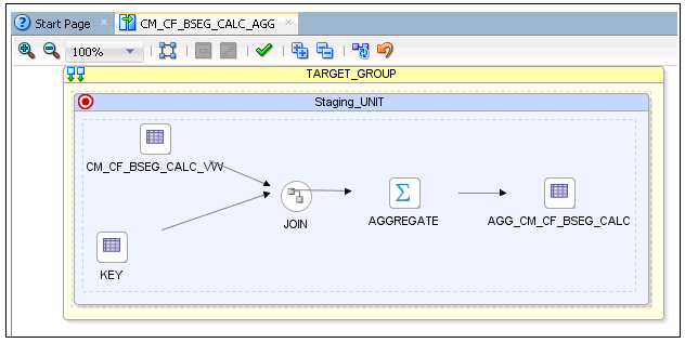
22. Click the target table. The Properties window is displayed.
23. Select “IKM BI Direct Load” from the Integrated Knowledge Module list. 
24. Click Save to save the mapping.
Creating Staging Tables in Fact Model
A staging table is created by the scheduling process prior to the interface execution. It optimizes the parallel execution of multiple slices of the same entity load.
The definition of the staging table structure is under the Staging folder. The staging table structure is similar to the target table structure, including a few additional columns. It should include IND_UPDATE in addition to the columns used in the mapping.
To create a staging table in the dimension model:
1. On the Oracle Data Integrator client, navigate to Models > User Customization > <product_name> > Staging.
In this example, ‘CCB’ is the product.
In this example, ‘CCB’ is the product.
2. Right-click the model and select New Datastore from the menu.
3. In the Datastore editor, enter the aggregate table name (STG_CM_CF_BSEG_CALC) in the Name field. Enter “STG_#GLOBAL.B1_JOB_ID” in the Resource Name field. 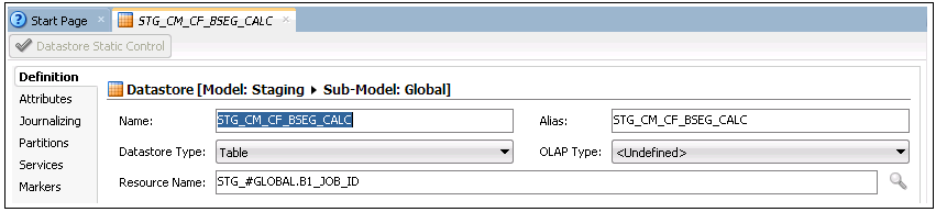
4. Click the Flexfields tab.
5. On the editor, unselect the Default check box for all columns. Enter “STG” and “CM_CF_BSEG_CALC” in the B1 Object Type and B1 Target Entity Name fields respectively.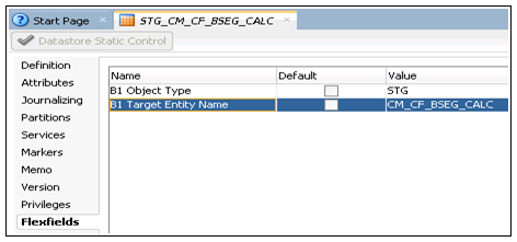
6. Navigate to Attributes tab.
7. Click + on right-hand corner to add columns to the datastore.
Add all columns that are in the fact table. In addition, add the dimension’s natural key column. The dimension natural keys (as specified in the aggregate table) should be included in the staging table.
The data type and length of the columns should match with that of the fact table.
Add all columns that are in the fact table. In addition, add the dimension’s natural key column. The dimension natural keys (as specified in the aggregate table) should be included in the staging table.
The data type and length of the columns should match with that of the fact table.
8. In addition to the above columns add the following:
• IND_UPDATE column with CHAR(1) as the data type.
• UPDATE_DTTM with DATE as the data type.
• JOB_NBR with NUMBER(19) as the data type. 
9. Click Save to save the datastore.
Creating Error Tables in Fact Model
An error table is created during the fact job execution, with its table structure similar to that of a staging table.
The error table is populated for late arriving dimensions. If a dimension record is not present in the dimension during the fact load, then the dimension key is populated as -99 and the record is populated in the error table. During the next fact load, data in the error table is looked up in the dimension table to find the records and correct the data in the fact table for the corrected dimension key.
After reprocessing all dimension keys for the fact record, it is deleted from the error table. To do this, ensure that the staging table structure definition is included in a model under the Staging folder. Set the flex fields appropriately.
To create an error table in the fact model:
1. Login to the Oracle Data Integrator client.
2. Navigate to Models > User Customization > <product name> > Staging.
In this example, ‘CCB’ is the product.
In this example, ‘CCB’ is the product.
3. Right-click the model and select New Datastore from the menu.
4. On the Datastore editor, enter “ERR_CM_CF_BSEG_CALC” in the Name field. Ensure the Resource Name is same as that of the error table name.

5. Navigate to the Flexfields tab.
6. Unselect the Default check box for the respective columns. Enter “ERR” and “CM_CF_BSEG_CALC” in the in B1 Object Type and B1 Target Entity Name columns respectively. 
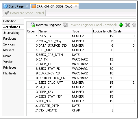
7. Navigate to the Attributes tab.
8. Click + on the right-hand corner to add columns to the datastore.
9. Add all columns from the fact table, and also add the dimension’s natural key column.
The dimension’s natural keys (as specified in the aggregate table) should be included in the staging table.
The data type and length of the columns should match with that of the fact table.
The dimension’s natural keys (as specified in the aggregate table) should be included in the staging table.
The data type and length of the columns should match with that of the fact table.
10. In addition to the above columns, add the following:
• IND_UPDATE column with CHAR(1) as the data type.
• UPDATE_DTTM with DATE as the data type.
• JOB_NBR with NUMBER(19) as the data type.
11. Click Save to save the datastore.
Creating Mapping to Load Facts
The data is loaded into Staging table from the Aggregate table. The Staging table is updated for dimension key by looking up the dimension tables. After the dimension keys are updated, the fact table is loaded with data.
To load data from an Aggregate table to a Staging table, and then to the fact table, follow these instructions:
1. Login to the Oracle Data Integrator client.
2. On the Designer, navigate to the Models > User Customization > <product_name> > Fact.
In this example, ‘CCB’ is the product.
In this example, ‘CCB’ is the product.
3. Right-click Mapping and select New Mapping from the menu.
4. On the mapping editor, enter “CM_CF_BSEG_CALC” in the Name field. Un-check the Create Empty Dataset check box.
5. Navigate to Models > User Customization > CCB > Staging.
6. Drag the Aggregate (AGG_CM_CF_BSEG_CALC) and staging (STG_CM_CF_BSEG_CALC) tables and drop them onto the mapping editor.
Provide an alias name (for example: “SRC”).
Provide an alias name (for example: “SRC”).
7. Map the columns from the Aggregate table to those from the Staging table.

8. Drag and drop the Staging table again.
All joins from the Staging table (SRC) to the dimension should be an outer join including all rows from staging and any rows that are available from dimension.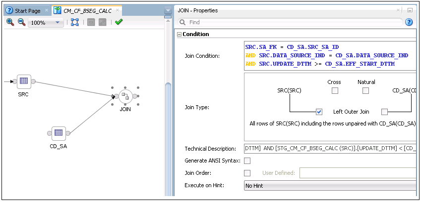
All joins from the Staging table (SRC) to the dimension should be an outer join including all rows from staging and any rows that are available from dimension.
9. Drag and drop the dimension and join the staging table with the dimension tables.
The join condition with type 2 dimension is as follows:
The join condition with type 2 dimension is as follows:
SRC.DIM_FK = DIM1.SRC_DIM_NK
and SRC.DATA_SOURCE_IND = DIM1.DATA_SOURCE_IND
and SRC.UPDATE_DTTM >= DIM1.EFF_START_DTTM
and SRC.UPDATE_DTTM < DIM1.EFF_END_DTTM
The join condition with type 1 dimension is as follows:
SRC.DIM_FK = DIM2.SRC_DIM_NK
and SRC.DATA_SOURCE_IND = DIM2.DATA_SOURCE_IND
10. Map the natural key columns of the target table (staging table) with that of the staging table. Select the KEY check box in the Properties window.
11. Select a dimension key and provide the transformation for that key in the properties inspector.
Replace the actual dimension name and dimension column names as follows:
Replace the actual dimension name and dimension column names as follows:
CASE WHEN SRC.DIM_FK IS NULL THEN #GLOBAL.B1_NULL_KEY
WHEN DIM.DIM_KEY IS NULL THEN #GLOBAL.B1_MISSING_KEY
ELSE DIM.DIM_KEY
END
12. Repeat step 11 for all dimension keys in the table.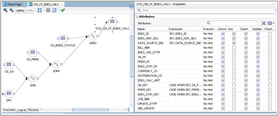
13. Drag and drop the fact table from the model.
14. Map all columns in the fact table with those in the staging table (the target for the dimension lookup). Select the Key check box to mark the key columns. 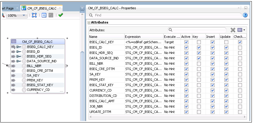
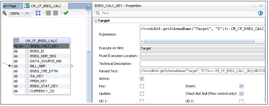
15. Map the surrogate key to the sequence. Then, unselect the Update check box.
16. Save the mapping.
17. Click the mapping editor to open the Properties window for the mapping.
18. Specify the target load order as SRC, staging table, and fact table.
In this example: SRC,STG_CM_CF_BSEG_CALC,CM_CF_BSEG_CALC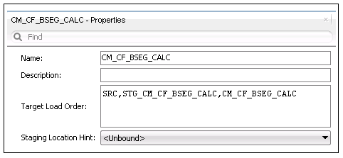
The logical mapping is complete. The figure below shows the mapping.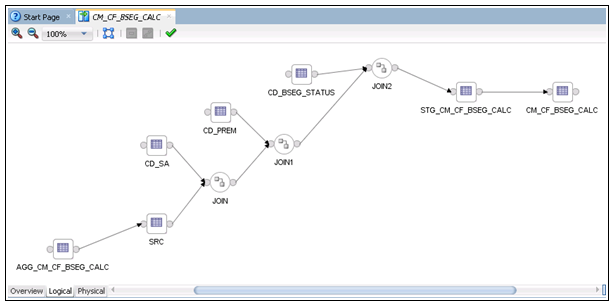
In this example: SRC,STG_CM_CF_BSEG_CALC,CM_CF_BSEG_CALC
The logical mapping is complete. The figure below shows the mapping.
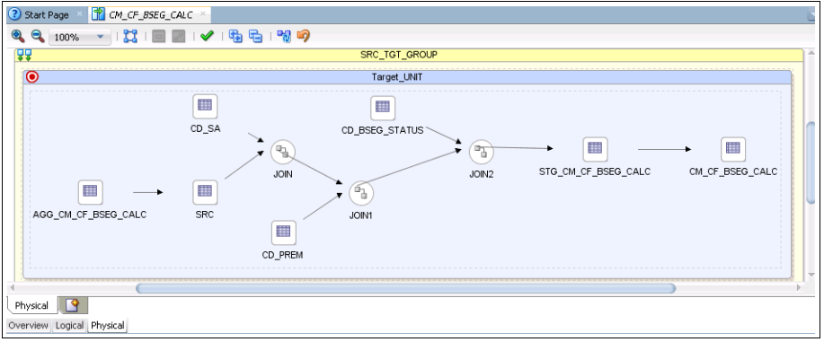
19. Navigate to the Physical tab and select the Context.
20. Click Save to save the mapping so that the physical mapping diagram is visible.
In this example, select “CCB7”.
In this example, select “CCB7”.
21. On the mapping diagram, click SRC. The respective Properties window is displayed.
22. Select “IKM BI Direct Load” from the Integration Knowledge Module drop-down list.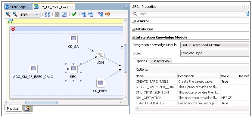
23. Click STG_CM_CF_BSEG_CALC staging table. The respective Properties window is displayed.
24. Select “IKM BI Fact Key Lookup” from the Integration Knowledge Module drop-down list.
Enter “Staging.ERR_CM_CF_BSEG_CALC” in the Value field for the ERR_TABLE_NAME option. (This option is set to get the error table name).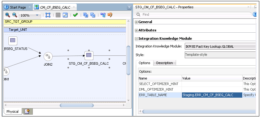
Enter “Staging.ERR_CM_CF_BSEG_CALC” in the Value field for the ERR_TABLE_NAME option. (This option is set to get the error table name).
25. Click the CM_CF_BSEG_CALC fact table. The respective Properties window is ready.
26. Select “IKM BI Direct Load” from the Integration Knowledge Module drop-down list.
27. Click Save to save the mapping.
Creating Packages in Fact Model
To create a package in the new fact model:
1. Login to the Oracle Data Integrator client.
2. On the Designer, navigate to Models > User Customization > Facts > Packages.
3. Right-click Package and select New Package from the menu.
4. On the package editor, enter “CM_PKG_CM_CF_BSEG_CALC” in the Name field.
5. Click the Diagram tab at the bottom of the editor.
6. In the Global Objects section, do the following:
a. Drag the following variables into the editor:
• B1_JOB_ID
• B1_DEF_MISSING_KEY
• B1_DEF_NULL_KEY
b. Modify the following variables to declare the variable:
• B1_JOB_ID
c. Modify B1_DEF_MISSING_KEY and B1_DEF_NULL_KEY to refresh variables.
d. Drag and drop the mapping to load the aggregate table, and then mapping to load the fact table into the editor. Connect them all in a sequence. 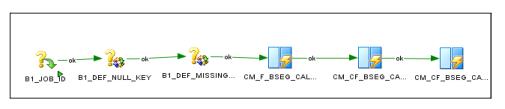
e. Click Save to save the changes and close the package editor.
7. Navigate to Packages and expand it. The new package is displayed.
8. Right-click Generate Scenario. Enter the scenario name and then click OK.
9. When prompted, select the startup variables.
10. Unselect B1_DEF_MISSING_KEY and B1_DEF_NULL_KEY (as they are refresh variables) and click OK.
11. Expand the package. In the list of scenarios, the new scenario object that was generated is displayed.
Configuring Entities in Fact Model
To configure a new entity in a custom fact:
1. Login to the Oracle Utilities Analytics Warehouse Administration user mapping.
2. On the ETL Configuration tab, click Target Entity.
3. Click Add. The Main Target Entity page is displayed.
4. Enter the appropriate values for the entity.
Specifying Dependencies in Fact Model
The dependency for Type 2 dimension should be specified in the fact. It is mentioned in the B1_OBJECT_MAP table for the custom fact.
Below is a sample query to insert the dependency. Ensure to add this merge query in the existing CM procedure to add the metadata in Oracle Utilities Analytics Warehouse.
Note: Refer to the Configuring CM Scenarios section for instructions to create a CM procedure.
merge
into b1_object_map tgt
using (select 'CCB' prod_flg
, 'CD_SA' source_object_name
, 'CM_CF_BSEG_CALC' target_object_name
, 1 seq
, 'DMDP' object_type_flg
from dual ) tgt_val
on ( tgt.prod_flg = tgt_val.prod_flg
and tgt.source_object_name = tgt_val.source_object_name
and tgt.target_object_name = tgt_val.target_object_name
and tgt.seq = tgt_val.seq)
when not matched
then insert
(
tgt.object_map_id
, tgt.prod_flg
, tgt.source_object_name
, tgt.target_object_name
, tgt.seq
, tgt.object_type_flg
, tgt.char_entity_flg
, tgt.upd_dttm
, tgt.upd_user
, tgt.owner_flg
)
values
(
b1_object_map_seq.nextval
, tgt_val.prod_flg
, tgt_val.source_object_name
, tgt_val.target_object_name
, tgt_val.seq
, tgt_val.object_type_flg
, null
, sysdate
, sys_context('userenv', 'os_user')
,'B1');
merge
into b1_object_map tgt
using (select 'CCB' prod_flg
, 'CD_PREM' source_object_name
, 'CM_CF_BSEG_CALC' target_object_name
, 2 seq
, 'DMDP' object_type_flg
from dual ) tgt_val
on ( tgt.prod_flg = tgt_val.prod_flg
and tgt.source_object_name = tgt_val.source_object_name
and tgt.target_object_name = tgt_val.target_object_name
and tgt.seq = tgt_val.seq)
when not matched
then insert
(
tgt.object_map_id
, tgt.prod_flg
, tgt.source_object_name
, tgt.target_object_name
, tgt.seq
, tgt.object_type_flg
, tgt.char_entity_flg
, tgt.upd_dttm
, tgt.upd_user
, tgt.owner_flg
)
values
(
b1_object_map_seq.nextval
, tgt_val.prod_flg
, tgt_val.source_object_name
, tgt_val.target_object_name
, tgt_val.seq
, tgt_val.object_type_flg
, null
, sysdate
, sys_context('userenv', 'os_user')
,'B1');
COMMIT;
Configuring Jobs in Fact Model
To configure a job for the custom fact:
1. Login to the Oracle Data Integrator client.
2. On the designer, navigate to Load Plans and Scenarios > Accelerators > Oracle Utilities Analytics Warehouse.
3. Right-click the B1_CFG_INSTANCE scenario and run in the context.
A fact job for that context is created. Also, dependency for the context specific dimensions for this fact job is created.
A fact job for that context is created. Also, dependency for the context specific dimensions for this fact job is created.
Alternately, execute the scenario from the Oracle Data Integrator console as follows:
1. Login to the Oracle Data Integrator console.
The Oracle Data Integrator console is deployed when the WebLogic agent for Oracle Data Integrator is created.
The URL format for the console is:
The Oracle Data Integrator console is deployed when the WebLogic agent for Oracle Data Integrator is created.
The URL format for the console is:
2. Login to the Work repository using the ‘SUPERVISOR’ credential.
3. In the browser, navigate to Runtime > Scenario/Load Plan > Folders > Accelerators > OUA.
4. Right-click the B1_CFG_INSTANCE scenario and execute it in the context. The scenario is executed successfully.
After executing the scenario successfully, enable the fact job in Oracle Utilities Analytics Warehouse Administration.
1. Login to Oracle Utilities Analytics Warehouse Administration.
2. On the ETL Configuration tab, click Job Configuration.
3. Search for the custom fact and edit it.
4. Select “Yes” from the Entity Active Flag drop-down list. The fact is enabled successfully.
Monitoring Job Executions
After the fact job is configured for customization and activated, monitor the job execution using Oracle Utilities Analytics Warehouse Administration or SQL Developer.
To monitor the fact job execution using Oracle Utilities Analytics Warehouse Administration:
1. Login to Oracle Utilities Analytics Warehouse Administration.
2. On the ETL Job Execution tab, enter the fact name.
3. Click Go to filter the data.
To view the latest execution, sort by the session end date.