Note:
- This tutorial requires access to Oracle Cloud. To sign up for a free account, see Get started with Oracle Cloud Infrastructure Free Tier.
- It uses example values for Oracle Cloud Infrastructure credentials, tenancy, and compartments. When completing your lab, substitute these values with ones specific to your cloud environment.
Configure SR-IOV interfaces for pods using Multus for VM-based Oracle Container Engine for Kubernetes nodes
Introduction
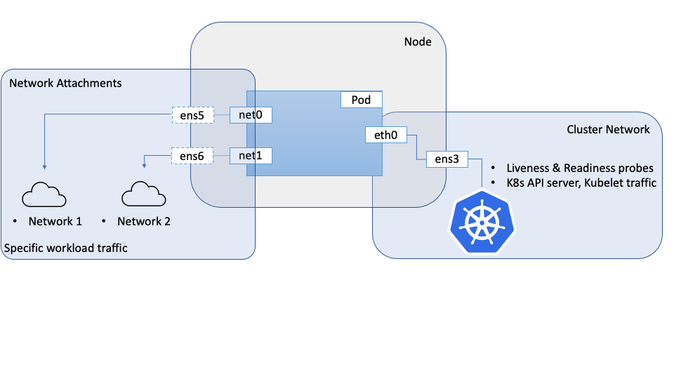
When highly network oriented workloads require setting up secondary network interfaces within pods, we can use a meta CNI like Multus to achieve this. The secondary network interfaces that are usually attached in these cases will have specialized networking capabilities or properties like Single Root IO Virtualization(SR-IOV).
In an earlier tutorial: Configure SR-IOV interfaces for pods using Multus for bare metal OKE nodes (you can acccess the link from the Related Links section), we covered how to achieve this on bare metal Kubernetes nodes on Oracle Cloud Infrastructure (OCI), where you can directly create Virtual Functions (VFs) on the hardware attached to the bare metal instance.
This tutorial follows a similar approach for Virtual Machine nodes in an Oracle Container Engine for Kubernetes (OKE) cluster, and takes a similar approach, with different configurations and plugins than those used on bare-metal nodes. There are significant differences in how the interfaces are created and managed between bare metal where you have full control over the hardware and virtual machines where a hypervisor abstracts your access to the underlying hardware and you do not have as much control over it.
The approach described here uses Multus to provide multiple interfaces to a pod, however the SR-IOV CNI and the associated device plug-in are not used. This is because the SR-IOV CNI requires access to the underlying hardware, the physical function (PF), which obviously poses a challenge on virtual machines. To overcome this challenge, we can use the OCI networking APIs for VNICs, to create a Virtual Function (VF) on the Physical Function(PF) like in the bare metal scenario and give the VM direct and unobstructed access to this VF. These VFs can be attached to a compute instance, including OKE nodes, as network interfaces. These interfaces/VFs can be moved to the network namespaces for pods, which allow the pod to directly and exclusively use the VF as a network interface. From the perspective of the Pods, it will not be able to distinguish between the two, and in both cases will have access to a VF that they can directly use.
To give a VM direct access to a VF, we need to launch the VM with the VFIO network attachment mode as opposed to the default paravirtualized mode. This choice is controlled by the launch mode for the compute instance. Once the network attachment mode is set as VFIO we can create network attachments using the OCI APIs, which creates VFs on the underlying PF and provides the VF directly to the VM. The OS on the host will recognize these as network interfaces. Once the VF is available to the VM, it can be moved to the pod namespace. In this model, the VFs are created using OCI APIs as opposed to system commands in the bare-metal scenario.
Objective
Configure SR-IOV interfaces for pods using Multus for VM-based Oracle Container Engine for Kubernetes nodes.
Prerequisites
- An OKE cluster with a node pool consisting of at least two VMs.
Note: This tutorial has been validated on OKE clusters with Flannel networking (Flannel as the primary CNI).
Task 1: Set up the nodes
Each node that requires access to SR-IOV interfaces must be prepared for hardware assisted network attachments before they can be used by the pods.
-
Boot the nodes in VFIO mode
-
Create a node pool and a set of nodes in your cluster.
-
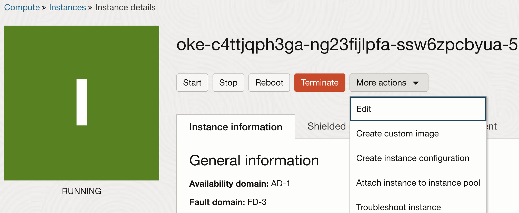
Once the nodes are created, edit the instance properties.
-
On the instance properties, click Show Advanced Options to view the additional properties. On the Launch Options tab, choose Hardware-assisted (SR-IOV) networking for the Networking type.
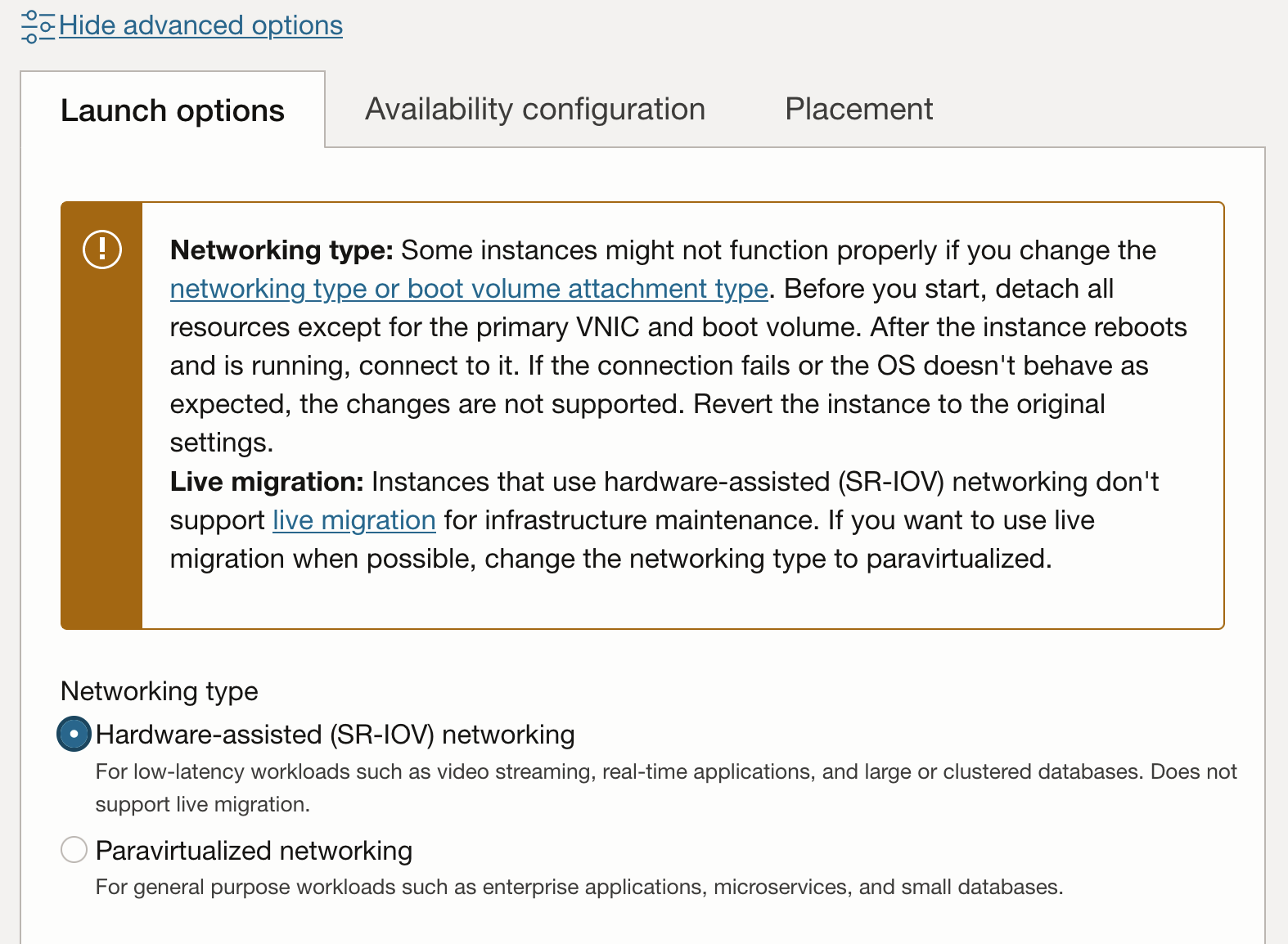
Note: Once an instance has been switched form paravirtualized network attachments to hardware assisted (SR-IOV or VFIO) mode, they are no longer eligible for live-migration for infrastructure maintenance.
-
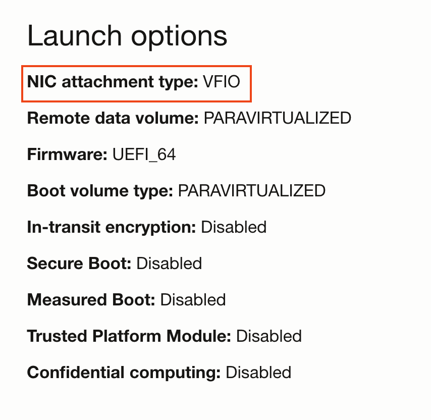
The update workflow will prompt you to reboot the instance. After reboot the instance will have VFIO network attachments. This can be verified on the console.
-
Another method to verify if your instances are using SR-IOV network attachments is to SSH on to the node and use
lspcito list the PCI devices on the VM. You should be able to see the underlying virtual function directly on the VM as opposed to a device using avirtiodriver (like the storage controller in the image below).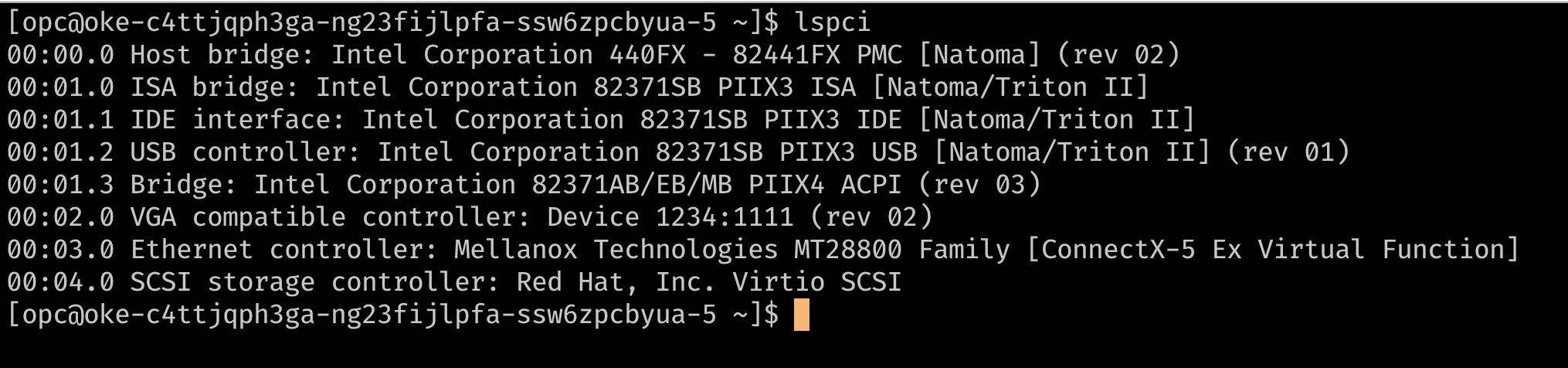
-
At this point the node has a single VNIC attachment, which is the primary VNIC used for all communications to the node. Since the instance is using hardware assisted network attachments, the network attachment is visible to the node as a virtual function on the underlying hardware. For pods to have exclusive use of a Virtual Function (VF), we need additional VFs on the VM. This can be provided using the console or API to add additional VNIC attachments to the instance. These VNIC attachments are VFs on the underlying PF. These can be verified with
lspci.
-
-
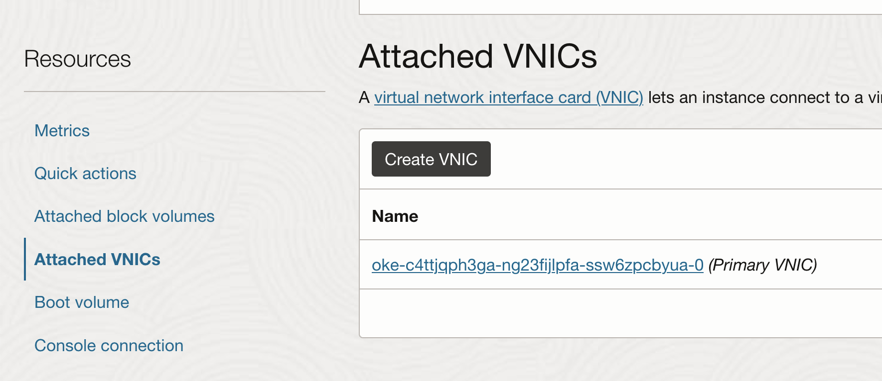
Add Additional VNIC Attachments
-
From the instance page, choose Attached VNICs and click Create VNIC.
-
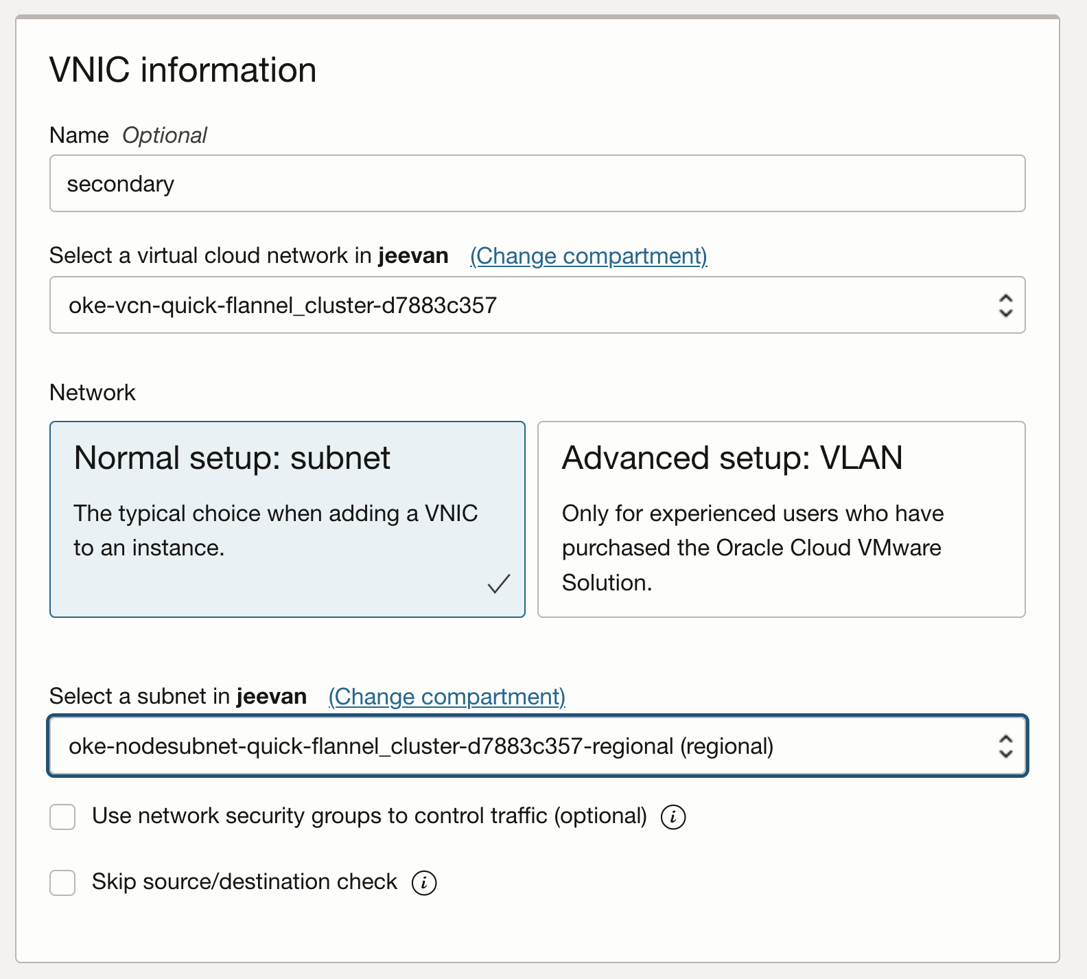
Configure the VNIC using the VCN and subnet that is needed.
-
Verify if the VNIC can be seen on the host as a Virtual Function as before, by SSH-ing on the node and running
lspci.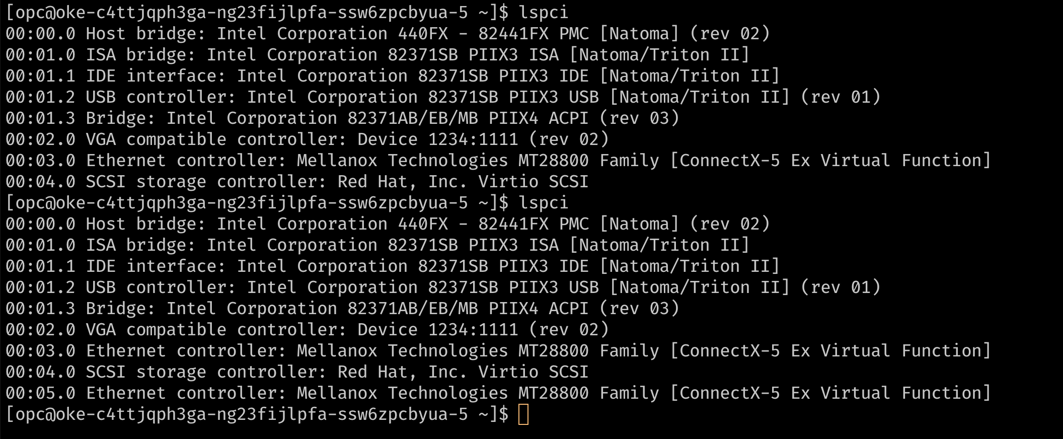
-
When you add a secondary VNIC to a Linux VM instance, a new interface (that is, an Ethernet device) is added to the instance and automatically recognized by the OS. However, DHCP is not active for the secondary VNIC, and you must configure the interface with the static IP address and default route.
-
-
Configure the OS for Secondary VNICs
-
OCI provides documentation and a script for configuring the OS for secondary VNICs. To configure the secondary VNIC, download the script on the node and run it based on the instructions provided in the OCI documentation.
Note: The secondary VNICs on each node must be set up by repeating these steps for each node. These steps can be optionally and automated using a custom
cloud_initscript for the nodes. -
Verify that the interface is now connected, with its IP address and default route. To check, use the command
ip addrornmcli.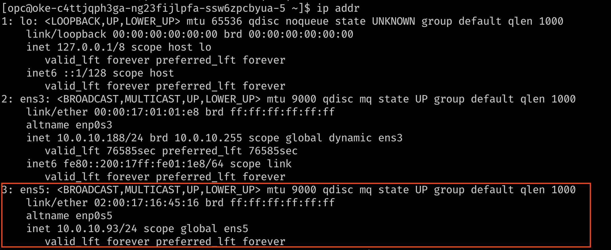
-
Optionally, verify the routing using a ping to reach the secondary IP addresses from each other. In the images below,
10.0.10.238is the secondary IP on a second node in the cluster.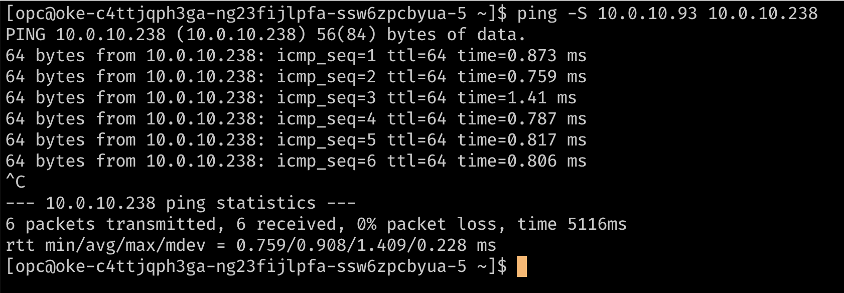
-
Task 2: Install a Meta-Plugin CNI (Multus)
Multus is a meta plug-in that can provide the VF information to a downstream CNI like the SR-IOV CNI plug-in for it to handle the network resource plumbing while enabling “Multi-homed” pods or pods with multiple network interfaces.
Note: Multus 4.0 onwards, Multus introduced a new client-server style deployment called the ‘thick plug-in’. The new thick plug-in supports additional features such as metrics which were not supported previously. This document uses the ‘thin’ plug-in as it consumes fewer resources.
-
To install Multus, run the following commands.
git clone https://github.com/k8snetworkplumbingwg/multus-cni.git && cd multus-cni
kubectl apply -f deployments/multus-daemonset.yml && cd ..
Note: On installation, the default image used by the daemonset that’s tagged
stableneeds the kubelet to be v1.20.x. If installing on an older cluster, edit the deamonset in the manifest and use the multus image tagv3.7.1.
This manifest creates a new CRD for the kind:NetworkAttachmentDefinition and provides the Multus binary on all nodes through a daemonset. You can verify the installation by ensuring that the Multus daemonset is running on your nodes.
Task 3: Attach multiple interfaces to pods
-
To attach additional interfaces to pods, we need a configuration for the interface to be attached. This is encapsulated in the custom resource of kind
NetworkAttachmentDefinition. This configuration is essentially a CNI configuration packaged as a custom resource. -
There are several CNI plugins that can be used alongside Multus to accomplish this. In the approach described here, the goal is to provide an SR-IOV Virtual Function exclusively for a single pod, so that the pod can take advantage of the capabilities without interference or any layers in between. To grant a pod exclusive access to the VF, we can leverage the host-device plug-in that enables you to move the interface in to the pod’s namespace so that it has exclusive access to it.
-
The examples below shows
NetworkAttachmentDefinitionobjects that configure the secondaryens5interface that was added to the nodes. Theipamplug-in configuration determines how IP addresses are managed for these interfaces. In this example, as we want to use the same IP addresses that were assigned to the secondary interfaces by OCI, we use the staticipamconfiguration with the appropriate routes.ipamconfiguration also supports other methods likehost-localordhcpfor more flexible configurations.## network attachment for the first node. Note the IPaddress assignment in the `ipam` configuration. cat << EOF | kubectl create -f - apiVersion: "k8s.cni.cncf.io/v1" kind: NetworkAttachmentDefinition metadata: name: sriov-vnic-1 spec: config: '{ "cniVersion": "0.3.1", "type": "host-device", "device": "ens5", "ipam": { "type": "static", "addresses": [ { "address": "10.0.10.93/24", "gateway": "0.0.0.0" } ], "routes": [ { "dst": "10.0.10.0/24", "gw": "0.0.0.0" } ] } }' EOF ## network attachment for the second node. Note the IPaddress assignment in the `ipam` configuration. cat << EOF | kubectl create -f - apiVersion: "k8s.cni.cncf.io/v1" kind: NetworkAttachmentDefinition metadata: name: sriov-vnic-2 spec: config: '{ "cniVersion": "0.3.1", "type": "host-device", "device": "ens5", "ipam": { "type": "static", "addresses": [ { "address": "10.0.10.238/24", "gateway": "0.0.0.0" } ], "routes": [ { "dst": "10.0.10.0/24", "gw": "0.0.0.0" } ] } }' EOF
Task 4: Deploy pods with multiple interfaces and test
Pods can now request additional interfaces using an annotation. The annotation lets the meta-plug-in (Multus) know what NetworkAttachmentDefinition (CNI Config) to use to provide additional interfaces when the pod is created.
Note: When using a static configuration like the one shown in this example, the pods need to have node affinity set, so that the pod is scheduled on the node where the desired host-device is available.
-
Here is an example with a test pod :
## Create the first pod cat << EOF | kubectl create -f - apiVersion: v1 kind: Pod metadata: name: testpod1 annotations: k8s.v1.cni.cncf.io/networks: sriov-vnic-1 spec: containers: - name: appcntr1 image: centos/tools imagePullPolicy: IfNotPresent command: [ "/bin/bash", "-c", "--" ] args: [ "while true; do sleep 300000; done;" ] EOF ## Create a second pod cat << EOF | kubectl create -f - apiVersion: v1 kind: Pod metadata: name: testpod2 annotations: k8s.v1.cni.cncf.io/networks: sriov-vnic spec: containers: - name: appcntr1 image: centos/tools imagePullPolicy: IfNotPresent command: [ "/bin/bash", "-c", "--" ] args: [ "while true; do sleep 300000; done;" ] EOF -
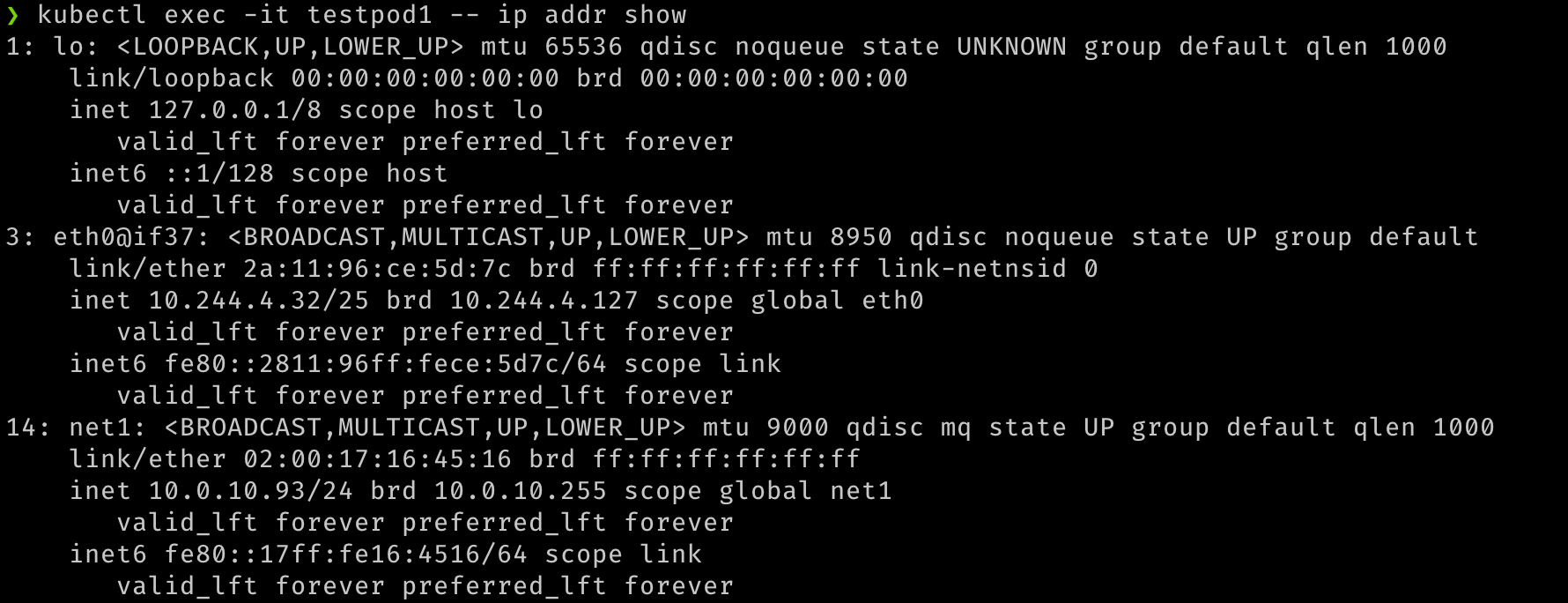
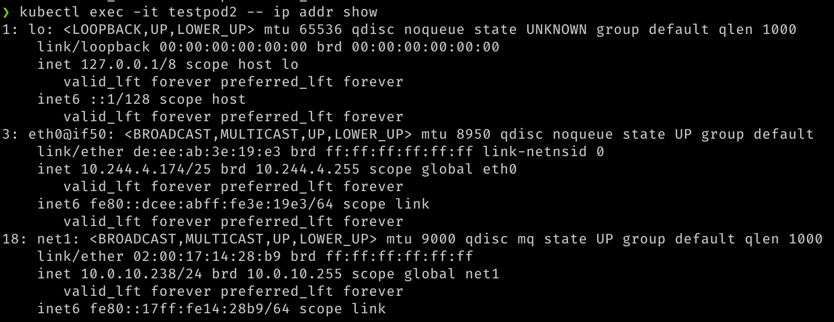
With two pods created, we should see that they are both running. We should be able to see that additional network interfaces were created during the creation of the pods. Multus will provide the
eth0interface that is backed by the default CNI (Flannel in this example) and an additionalnet1interface that is the SR-IOV Virtual Function. You candescribethe pods and observe the Events section of the output to see the various events, including the interfaces being attached to the pod.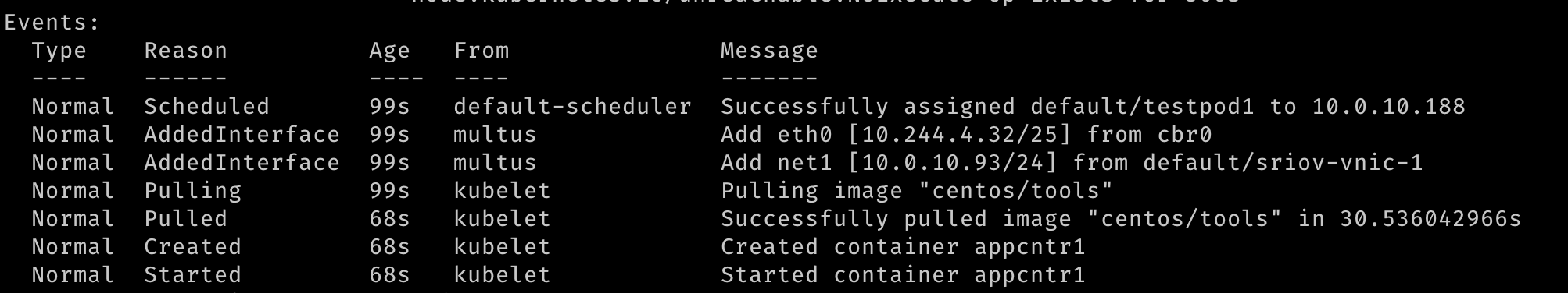
-
Once the pods have started, we can perform a quick test.
## Verify that both pods have two interfaces. An `eth0` on the overlay and a `net1` which is the VF, along with the IP address for the secondary VNIC. kubectl exec -it testpod1 -- ip addr show kubectl exec -it testpod2 -- ip addr show -
The output should be similar to the following images.
-
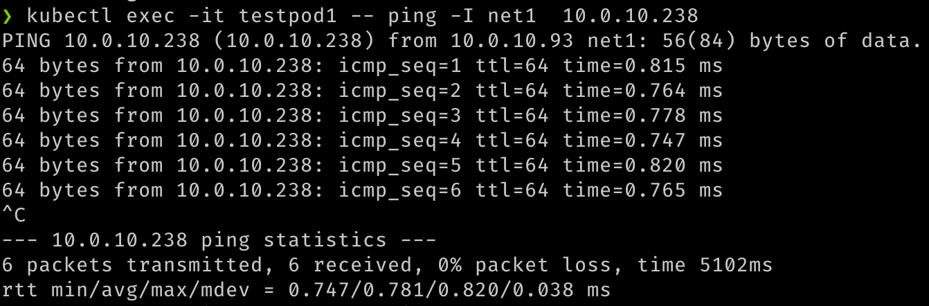
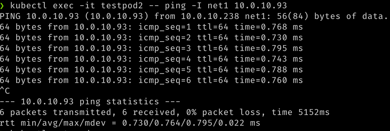
We can also verify the communication between the two pods over these secondary interfaces.
## test communication kubectl exec -it testpod1 -- ping -I net1 <ip address for secondary vnic on the other pod/node> kubectl exec -it testpod2 -- ping -I net1 <ip address for secondary vnic on the other pod/node> -
The output should be similar to the following images.
-
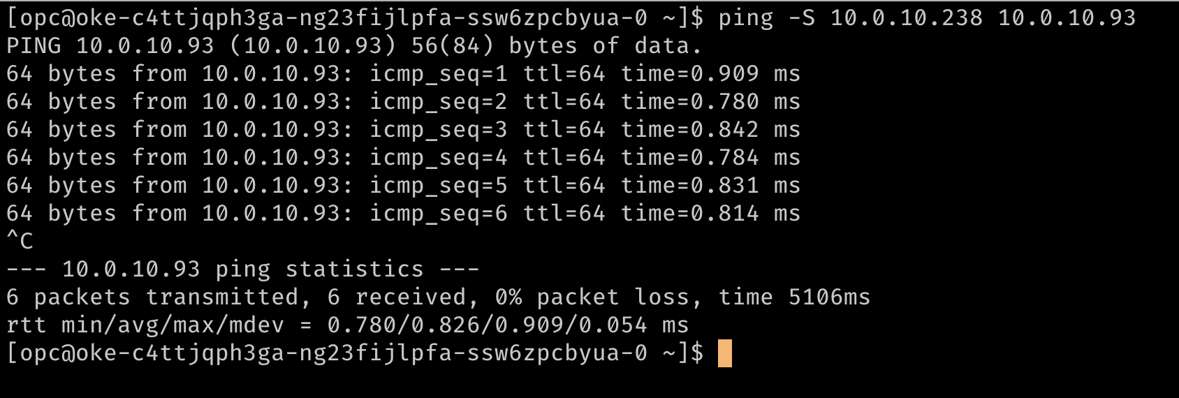
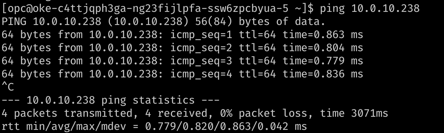
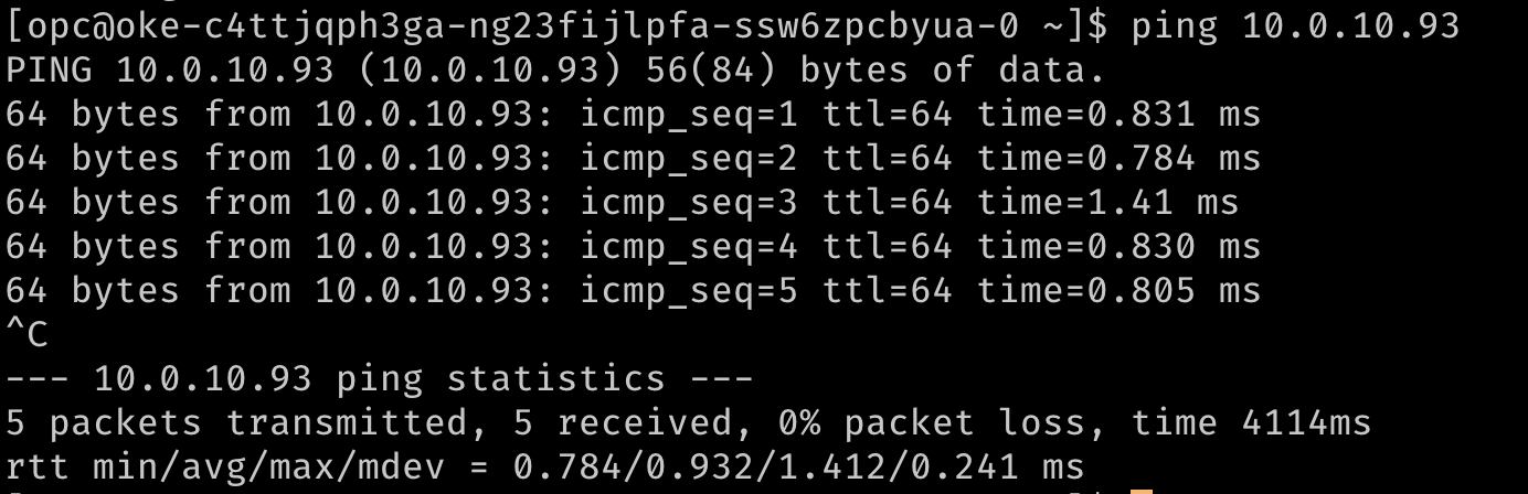
We can also validate that the pods are routable using their network attachments, by trying to reach them from the VMs or any other source within the VCN.
## Test that the pod is routable from outside Kubernetes. This is executed from node1. ping 10.0.10.238 ## similarly, from node 2 ping 10.0.10.93 -
The output should resemble the following images.
Related Links
Acknowledgments
- Author - Jeevan Joseph (Principal Product Manager)
More Learning Resources
Explore other labs on docs.oracle.com/learn or access more free learning content on the Oracle Learning YouTube channel. Additionally, visit education.oracle.com/learning-explorer to become an Oracle Learning Explorer.
For product documentation, visit Oracle Help Center.
Configure SR-IOV interfaces for pods using Multus for VM-based Oracle Container Engine for Kubernetes nodes
F80585-01
May 2023
Copyright © 2023, Oracle and/or its affiliates.