Note:
- This tutorial requires access to Oracle Cloud. To sign up for a free account, see Get started with Oracle Cloud Infrastructure Free Tier.
- It uses example values for Oracle Cloud Infrastructure credentials, tenancy, and compartments. When completing your lab, substitute these values with ones specific to your cloud environment.
Configure a pfSense High Availability active/passive cluster with Corosync/Pacemaker on Oracle Cloud Infrastructure
Note: pfSense is not officially supported on Oracle Cloud Infrastructure by Netgate or Oracle. Contact the pfSense support team before trying this tutorial.
Introduction
Oracle Cloud Infrastructure (OCI) is a set of complementary cloud services that enable you to build and run a wide range of applications and services in a highly available hosted environment. Oracle Cloud Infrastructure (OCI) offers high-performance compute capabilities (as physical hardware instances) and storage capacity in a flexible overlay virtual network that is securely accessible from your on-premises network.
pfSense is a free and open source firewall and router that also features unified threat management, load balancing, multi WAN, and more.
Objective
Setup pfSense virtual appliance in a high availability active/passive configuration with the help of Corosync/Pacemaker in OCI.
Prerequisites
- Access to an Oracle Cloud tenancy
- A Virtual Cloud Network setup in the tenancy
- All required policy setup for Oracle Object Storage, Virtual Cloud Networks, Compute and Custom Images.
Points to Note
- In this tutorial, we have one regional Virtual Cloud Network setup with two subnets: public and private with the CIDR of 192.0.2.0/29 and 192.0.2.8/29 respectively
- Primary instance - Node1, secondary instance - Node2
- Node1 hostname - “pfSense-primary” and IP: 192.0.2.2/29
- Node2 hostname - “pfSense-secondary” and IP: 192.0.2.5/29
- You can use the pfSense Edit File tool located in the pfSense console, Diagnostics, Edit file to make file changes.
- The term pfSense Shell is used in this tutorial, you can access the shell by ssh’ing into the instance and selecting 8 in the pfSense menu.
Task 1: Install two pfSense Virtual Appliances on Oracle Cloud
In this tutorial, we will use two pfSense virtual appliances for High Availability. You can setup multiple nodes based on your requirements. Follow the steps in this tutorial Install and Configure pfSense on Oracle Cloud Infrastructure.
Note:
- The two nodes should be setup in different Availability Domains and should be able to ping each other.
- You can have these nodes setup in different Virtual Cloud Networks or Regions, but make sure you have proper Peering Gateways and Route Tables defined to allow nodes to access one another.
- If you are not able to ping the nodes from one another, verify your pfSense firewall rules as well as the Oracle Cloud Security List associated with your instance and allow ICMP traffic.
Install the required packages
-
FreeBSD repos are disabled by default. To enable FreeBSD repos, follow these steps:
- Set FreeBSD:
{ enabled: yes } in /usr/local/etc/pkg/repos/FreeBSD.conf - Set FreeBSD:
{ enabled: yes } in /usr/local/share/pfSense/pkg/repos/pfSense-repo.conf
- Set FreeBSD:
-
After enabling the FreeBSD repos, update the package manager.
Node1@ pkg update Node2@ pkg updateNote: This will update the package manager and the repo metadata.
-
Install the following four packages reqired to setup the high availability cluster.
- Pacemaker
- Corosync
- Crmsh
- OCI CLI
Run the following commands for installation
Node1@ pkg install pacemaker2 corosync2 crmsh devel/oci-cli
Node2@ pkg install pacemaker2 corosync2 crmsh devel/oci-cli
Follow the prompts to complete the installation.
Task 3: Setup Pacemaker/Corosync on the instances
Configure Corosync
-
Create a new Corosync conf file by running the following command in both the instances.
Node1@ touch /usr/local/etc/corosync/corosync.conf Node2@ touch /usr/local/etc/corosync/corosync.conf -
Paste the following config into the script on both nodes.
Note: Ensure that you replace your IP addresses in the node list.
# Please read the corosync.conf.5 manual page
totem {
   version: 2
   crypto_cipher: none
   crypto_hash: none
   transport: udpu
}
logging {
   fileline: off
   to_logfile: yes
   to_syslog: yes
   logfile: /var/log/cluster/corosync.log
   debug: on
   timestamp: on
logger_subsys {
   subsys: QUORUM
   debug: on
   }
}
nodelist {
   node {
       ring0_addr: 192.0.2.2 # make sure to replace with your IP
       nodeid: 1
       }
   node {
       ring0_addr: 192.0.2.5 # make sure to replace with your IP
       nodeid: 2
       }
   }
quorum {
   # Enable and configure quorum subsystem (default: of
   # see also corosync.conf.5 and votequorum.5
   provider: corosync_votequorum
}
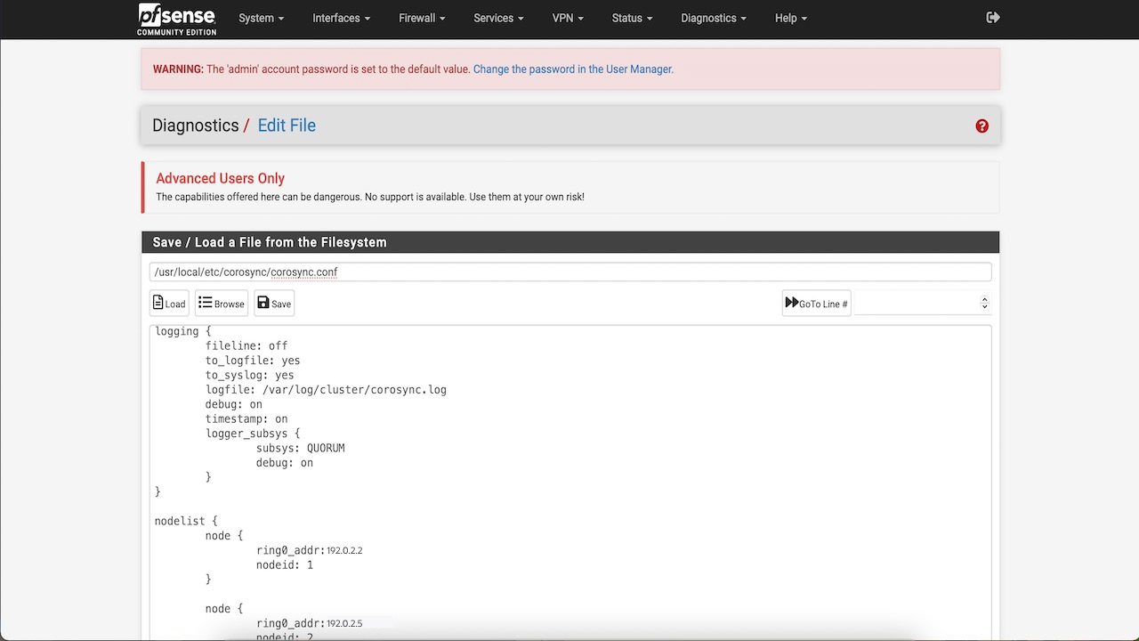
If you try to start Corosync now, it will fail with the error message “No space left on device”.
Enable RAM disk on both nodes
Corosync and Pacemaker rely on /var directory for their runtime, and if you did a default install, the space available to /var is very limited. You must setup and use memory (RAM) for the /var and /tmp directories, it will also help us boost performance.
-
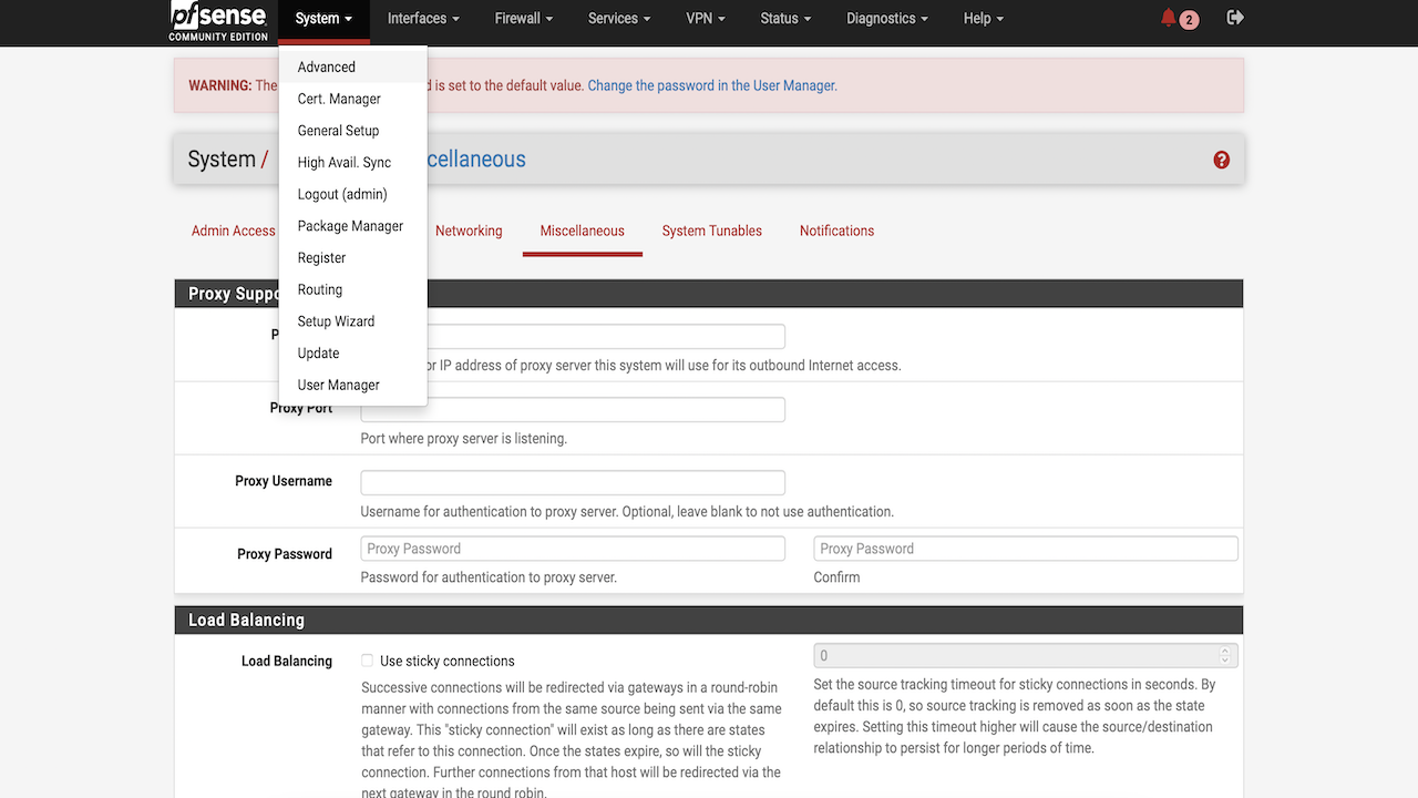
In your pfSense console, navigate to System, click Advanced, and then click Miscellaneous.
-
Scroll down to Ram Disk Settings and select the Use Ram Disks check box.
-
Enter the RAM disk size you want to allocate to
/tmpand/vardirectories. -
Save the configuration. You will be prompted to reboot for the first time you enable RAM Disk, later on you can increase or decrease the RAM Disk size on the go.

Note: Since we are using Ram Disks, in case of a System Shutdown, all our files in
/tmpand/varwill be lost. We must setup a startup script (rc.d file) which will create the directories that Corosync and Pacemaker need to function properly. -
Open the file
/usr/local/etc/rc.d/corosyncand add the following lines to the code after line 17 on both nodes.mkdir -p /var/lib/corosync mkdir -p /var/run/qb chmod 777 /var/run/qb -
After you have made the changes the Jle will look something like this :
#!/bin/sh
     # PROVIDE: corosync
     # REQUIRE: LOGIN FILESYSTEMS
     # KEYWORD: shutdown
     . /etc/rc.subr
     name="corosync"
     rcvar="corosync_enable"
     start_precmd="corosync_precmd"
     corosync_precmd()
     {
         if [ `${SYSCTL_N} kern.ipc.maxsockbuf` -lt 18874368 ]; then
             err 3 "sysctl:kern.ipc.maxsockbuf must be at least 18874
         fi
         mkdir -p /var/lib/corosync
         mkdir -p /var/run/qb
         chmod 777 /var/run/qb
      }
     load_rc_config $name
     : ${corosync_enable:=YES}
     command="/usr/local/sbin/corosync"
     run_rc_command "$1"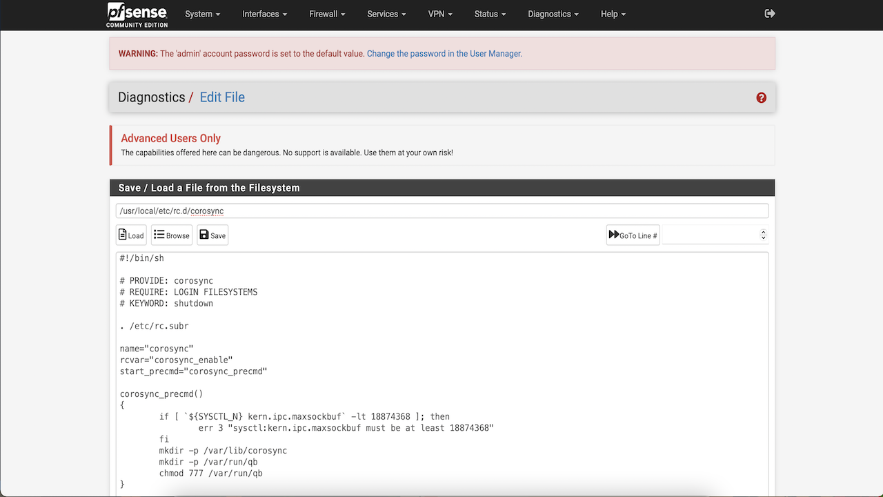
Start Corosync and Pacemaker service on all nodes
We can now add corosync_enable=YES and pacemaker_enable=YES to the /etc/rc.conf file. Run the following command on all nodes.
Node1@ sysrc corosync_enable=YES
Node2@ sysrc corosync_enable=YES
Node1@ sysrc pacemaker_enable=YES
Node2@ sysrc pacemaker_enable=YES
Node1@ service corosync start
Node2@ service corosync start
Node1@ service pacemaker start
Node2@ service pacemaker start
Note:
- It will take a few seconds to start Pacemaker.
- If you get an error message when trying to start Corosync: E
RROR: sysctl:kern.ipc.maxsockbuf must be at least 18874368, go to the pfSense console, click System, then click Advanced, and then click System Tunables and update the value forsysctl:kern.ipc.maxsockbufon all nodes.
Check the cluster status
-
Now that we have Pacemaker and Corosync running on all nodes, let’s check the cluster status. Run the following command to check the status:
Node1@ crm status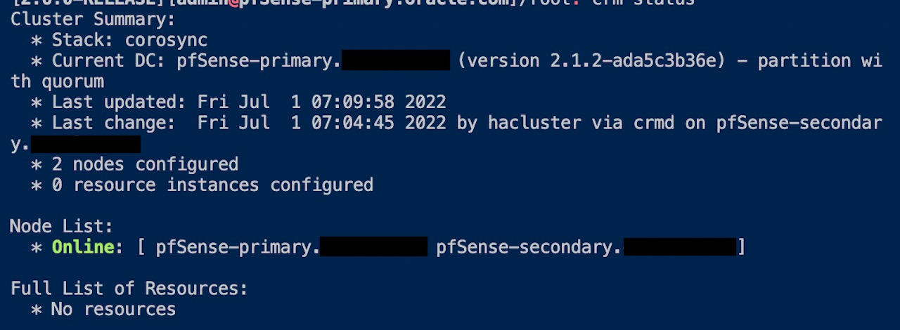
-
Disable Stonith for now as we are not covering Stonith in this tutorial.
Node1@ crm configure property stonith-enabled=false
Node2@ crm configure property stonith-enabled=false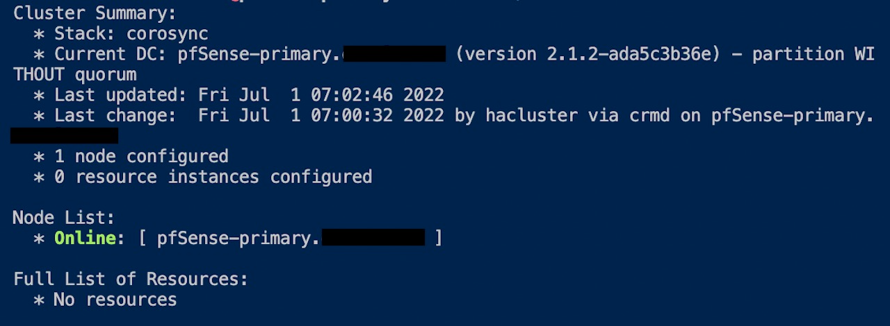
As you can see in the image, the status tells you that 2 nodes are configured and online.
Note:
- If you do not see that both nodes are configured and online as shown in the image, it indicates that only one instance is configured and is online. This means the nodes are not able to talk to each other.
- To resolve this, check the pfSense and Oracle Cloud Security Lists to Allow UDP and ICMP traffic.
Task 4: Setup Oracle Cloud Infrastructure CLI
We need OCI CLI to move and associate the Virtual Floating IP between the nodes on the infrastructure level. We already installed the OCI CLI earlier with other packages, now we will setup the config. We want to use instance principals to authorize our CLI commands. You can learn more about Instance Principals. and OCI cli
Follow this blog and setup Oracle Cloud Infrastructure instance principals.
Setup Virtual Floating IP
In this tutorial, we will use 192.0.2.3/29 as the virtual floating IP. We cannot setup a IPaddr2 heartbeat in pfSense which is FreeBSD based. If we tried it anyway, it will throw an error “IP is not available”, the package IP is linux only. We will setup a IPaddr heatbeat instead.
-
Open
/usr/local/lib/ocf/resource.d/heartbeat/IPaddrin the file editor. -
Add a few lines of code that will initiate the OCI CLI to move the IP from one vNIC to another. Add the following lines of code after line 584 in the add_interface() method of the script.
-
Assign node1vnic, node2vnic, vnicip and hostname values in the script. You can find your vNIC OCID’s in the Oracle Cloud Console, Compute, Attached vNICs menu.
else
##### OCI vNIC variables
    server="`hostname -s`"
    node1vnic="<node1vnic>"
    node2vnic="<node2vnic>"
    vnicip="<floating_IP>"
    export LC_ALL=C.UTF-8
    export LANG=C.UTF-8
    touch /tmp/ip_switch_error.log
##### OCI/IPaddr Integration
    if [ $server = "<host_name>" ]; then
        /usr/local/bin/oci network vnic assign-private-ip --auth instance_principal --unassign-if-already-assigned --vnic-id $node1vnic  --ip-address $vnicip >/tmp/ip_switch_error.log 2>&1
    else
        /usr/local/bin/oci network vnic assign-private-ip --auth instance_principal --unassign-if-already-assigned --vnic-id $node2vnic  --ip-address $vnicip >/tmp/ip_switch_error.log 2>&1
    fi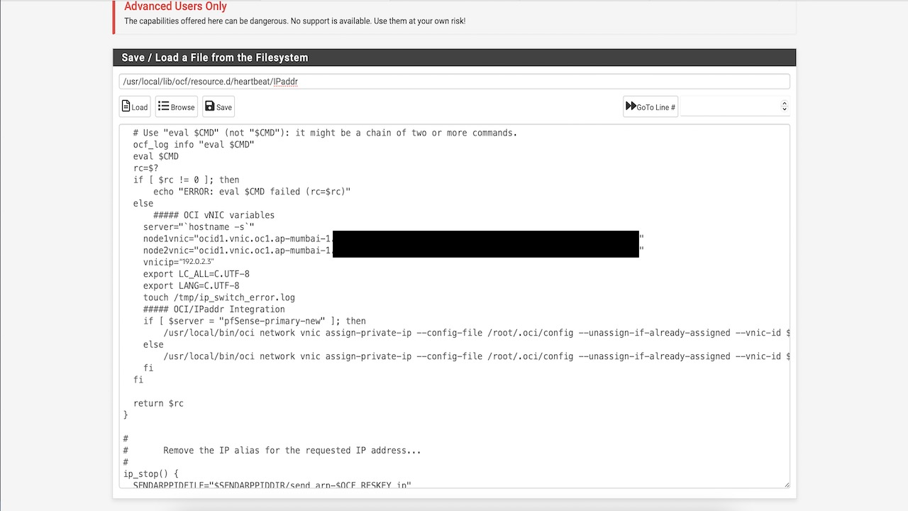
-
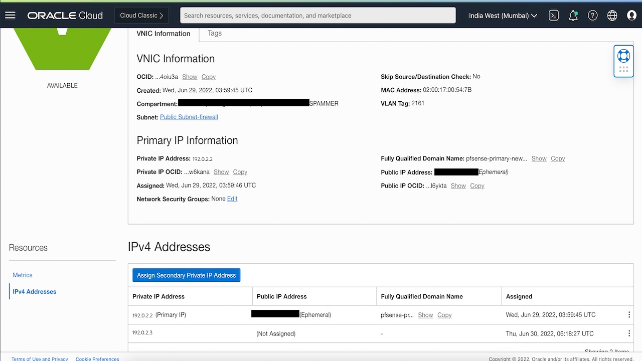
For Node 1: In Oracle Cloud Console go to Compute, then click pfSense-primary, and then click Attached vNIC’s. Select the primary vNIC and add a secondary private IP (same as the floating_IP in above script)
-
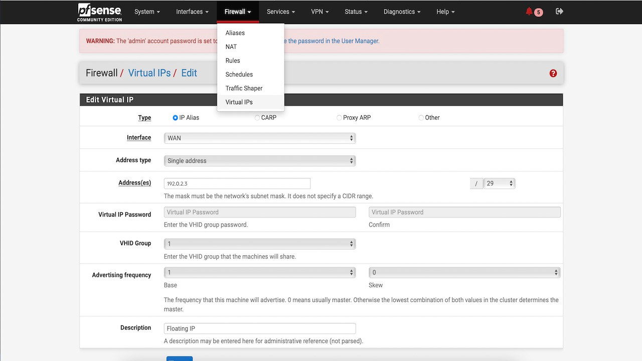
For both Nodes : In the pfSense console go to firewall, and then click Virtual IPs and add a IP Alias (same as floating_IP in the above script).
Set up Heartbeat
-
In pfSense shell, run the following command on Node 1.
crm configure primitive IP ocf:heartbeat:IPaddr params ip=192.0.2.3 cidr_netmask="29" nic=”vtnet0” op monitor interval="5s" -
In this tutorial, 192.0.2.3 is the floating IP. Ensure that you replace the ip, netmask and nic values with your values. This should create a IP resource in Pacemaker.
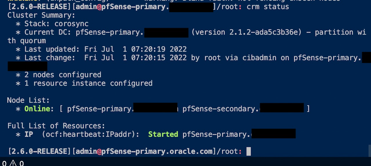
If you run crm status now, you will see two nodes online and one resource available which is pointing to pfSense-primary. You can also run ipconfig vtnet0 to check if the Virtual IP is now associated with the interface on the primary node.
Test Failover
Current State
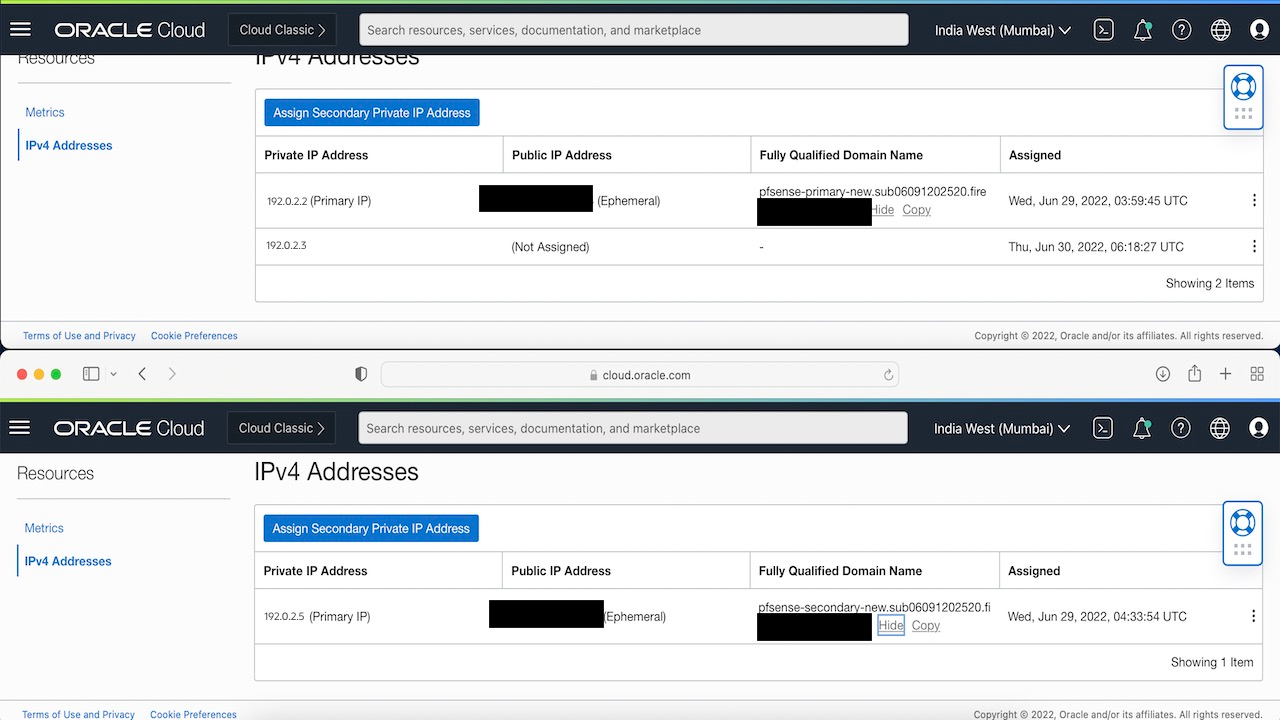
-
Run the following command to force a switch over :
crm resource move IP pfSense-secondary.example.com -
Run
crm statuscommand and you will see that the floating IP resource is now moved to pfSense-secondary. -
Check the Oracle Cloud Console vNIC avachments for you nodes, you will see that the floating IP has now moved to the second node.
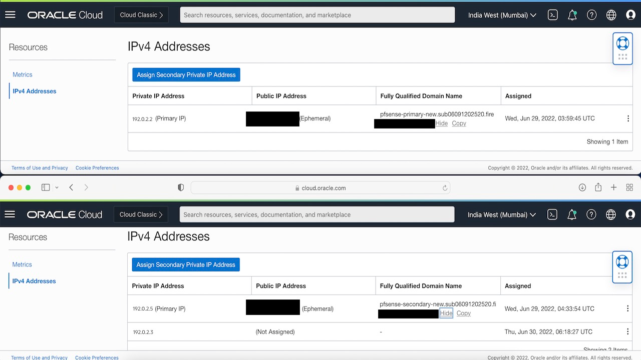
Note: If you try to shutdown now, the resource will move to stopped state as it won’t be able to figure out which node to deem as Master, since pfSense needs atleast 50% votes to assign a master. Since, we have only 2 nodes and one of them is down, Pacemaker won’t be able to set one as master.
-
Run the following command to ignore the 50% votes policy:
crm configure property no-quorum-policy=ignore -
Now test a shutdown and you can see the Floating IP move.
Task 5: Setup XLMRPC and pfsync
We want our nodes to have a synced state if we want to have a truly highly available cluster, just moving the IP’s isn’t going to do it. We need to setup another set of vNIC’s on each of our instances for the sync.
Setup Sync interface
-
For Both Nodes : Go to Compute, select the instance, open Attached vnics, and then click create vnic.
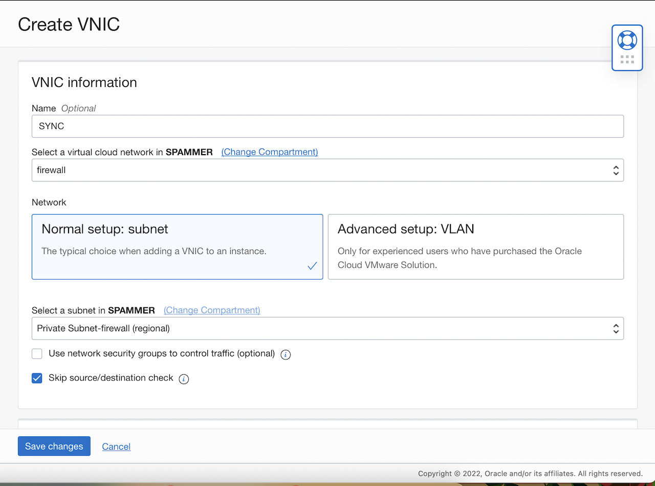
-
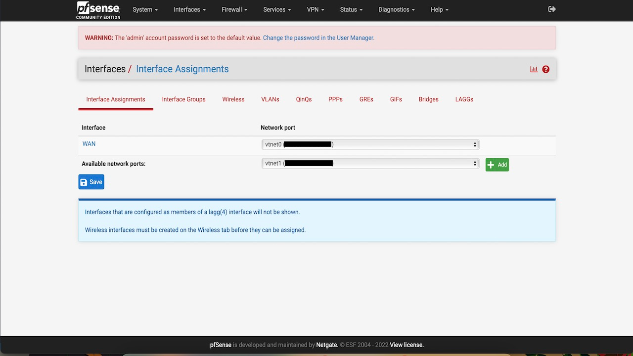
Once the vNIC is created and attached, go to pfSense console, click interfaces, then click Assignments and add the newly detected interface.
-
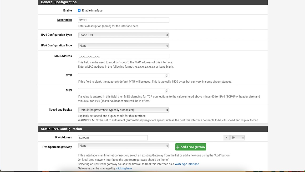
Click on the newly assigned interface and setup it’s config.
-
Assign the static IPv4 address and subnet mask we created in the earlier step in OCI console.
-
Click Save and apply changes.
Setup High Availability on the primary node
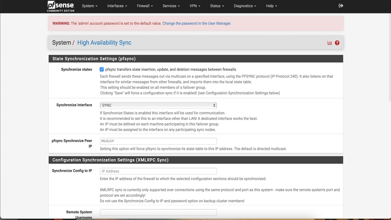
- Go to pfSense console, click System, and then click High Availability Sync.
- Enable pfsync state sync.
- Choose the sync interface.
- Add the secondary node IP.
- XMLRPC sync config : Add the secondary node IP.
- Set the user name and password and check what all you want to synchronize.
- Click Save and Apply.
Setup High Availability on the secondary node
- Go to pfSense console, click System, and then click High Availability Sync.
- Enable pfsync state sync.
- Choose the sync interface.
- Add the primary node IP.
- Click Save and Apply.
The firewall states are synced between both nodes and you can try and add a firewall rule on your primary instance, you will see the same appears on your secondary node as well. We can now try and test failover again with a system shutdown.
Related Links
- pfSense Website
- Availability Domains
- Peering Gateways
- Security List
- Troubleshooting Full Filesystem or Inode Errors
- Calling Services from an Instance
- Calling OCI CLI Using Instance Principal
Acknowledgments
Author - Mayank Kakani (OCI Cloud Architect)
More Learning Resources
Explore other labs on docs.oracle.com/learn or access more free learning content on the Oracle Learning YouTube channel. Additionally, visit education.oracle.com/learning-explorer to become an Oracle Learning Explorer.
For product documentation, visit Oracle Help Center.
Configure a pfSense High Availability active/passive cluster with Corosync/Pacemaker on Oracle Cloud Infrastructure
F70197-02
September 2022
Copyright © 2022, Oracle and/or its affiliates.