Note:
- This tutorial requires access to Oracle Cloud. To sign up for a free account, see Get started with Oracle Cloud Infrastructure Free Tier.
- It uses example values for Oracle Cloud Infrastructure credentials, tenancy, and compartments. When completing your lab, substitute these values with ones specific to your cloud environment.
Set up an Oracle Cloud Infrastructure Site-to-Site VPN with Static Routing Between two OCI Regions
Introduction
When your applications, databases, or services are distributed across different Oracle Cloud Infrastructure (OCI) regions or tenants, the preferred method for enabling network communication between them is Remote Peering Connection (RPC) peering. If RPC peering is not feasible, an alternative is to establish an OCI Site-to-Site VPN IPSec connection. While OCI does not directly support creating an OCI Site-to-Site VPN IPSec using the Dynamic Routing Gateway (DRG), you can configure a custom VPN endpoint (like Libreswan) on one side and utilize the DRG on the other to achieve this connection.
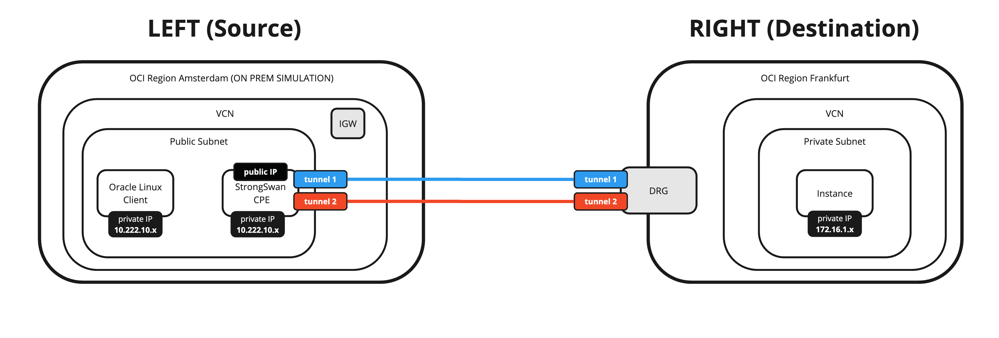
You can also use this method if you need to set up an OCI Site-to-Site VPN between on-premises and OCI and do not want to use the DRG as the Virtual Private Network (VPN) endpoint but your own custom VPN endpoint.
Objectives
-
Set up an OCI Site-to-Site VPN with static routing between two OCI regions using Libreswan as a Customer Premises Equipment (CPE) on one side and DRG on the other side.
We will connect two different OCI regions using an IPSec VPN with two tunnels and with Equal Cost Multi-Path (ECMP) enabled. We will use a CPE with Libreswan software in one OCI region and the OCI Site-to-Site VPN configured on the DRG in the other region.
Prerequisites
-
Create two OCI regions.
-
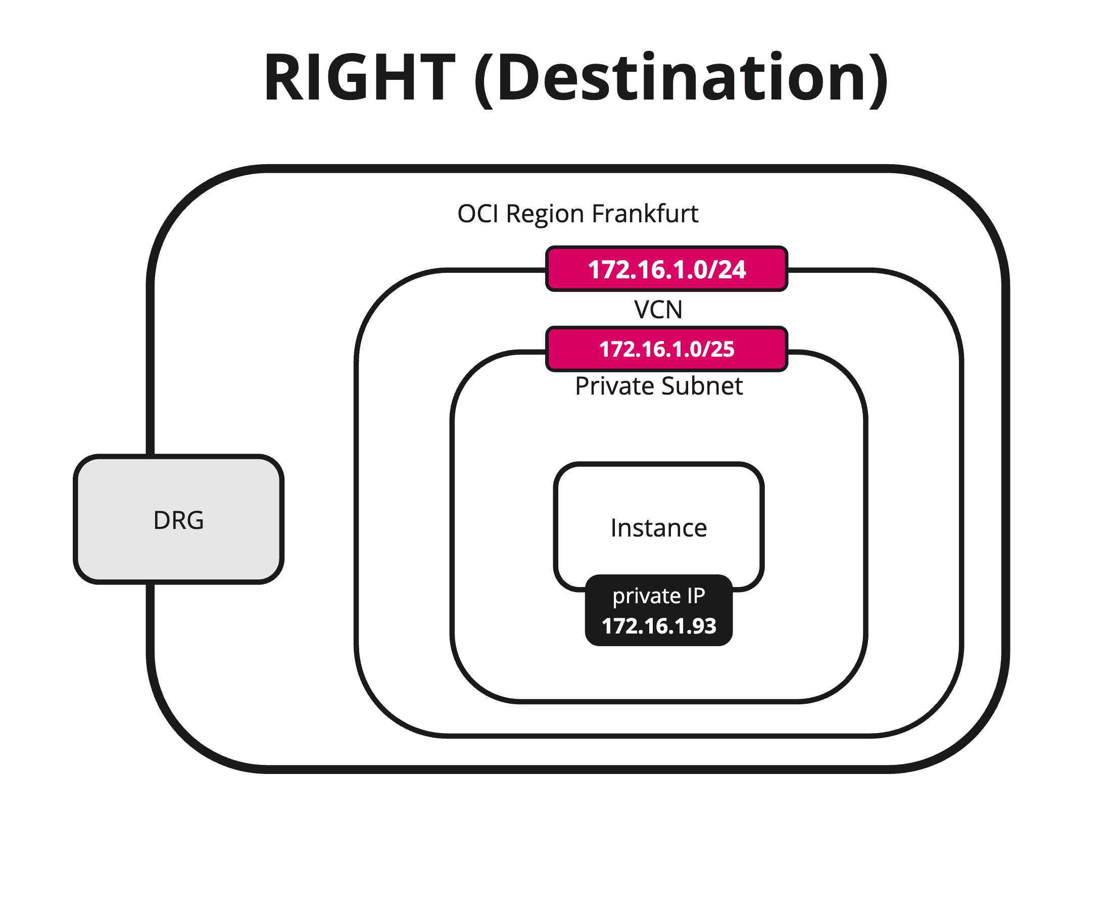
OCI Region 1 (Destination):
- Virtual Cloud Network (VCN)
- Private Subnet
- DRG
- VCN Attachments
- Instances
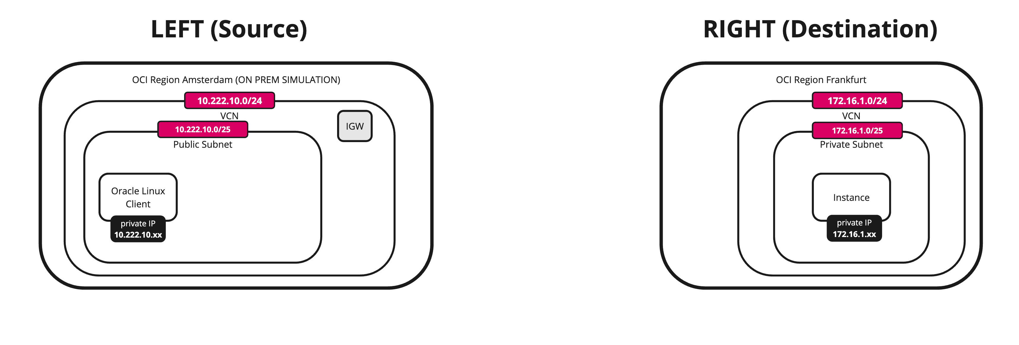
In this region the DRG will be the VPN endpoint and all traffic will be routed using the Internet connection of the DRG.
-
OCI Region 2 (Source):
- VCN
- Public Subnet
- Internet Gateway
- Instances
In this region the Libreswan CPE (instance inside OCI) will be the VPN endpoint and all traffic will be routed using the Internet connection of the internet gateway.
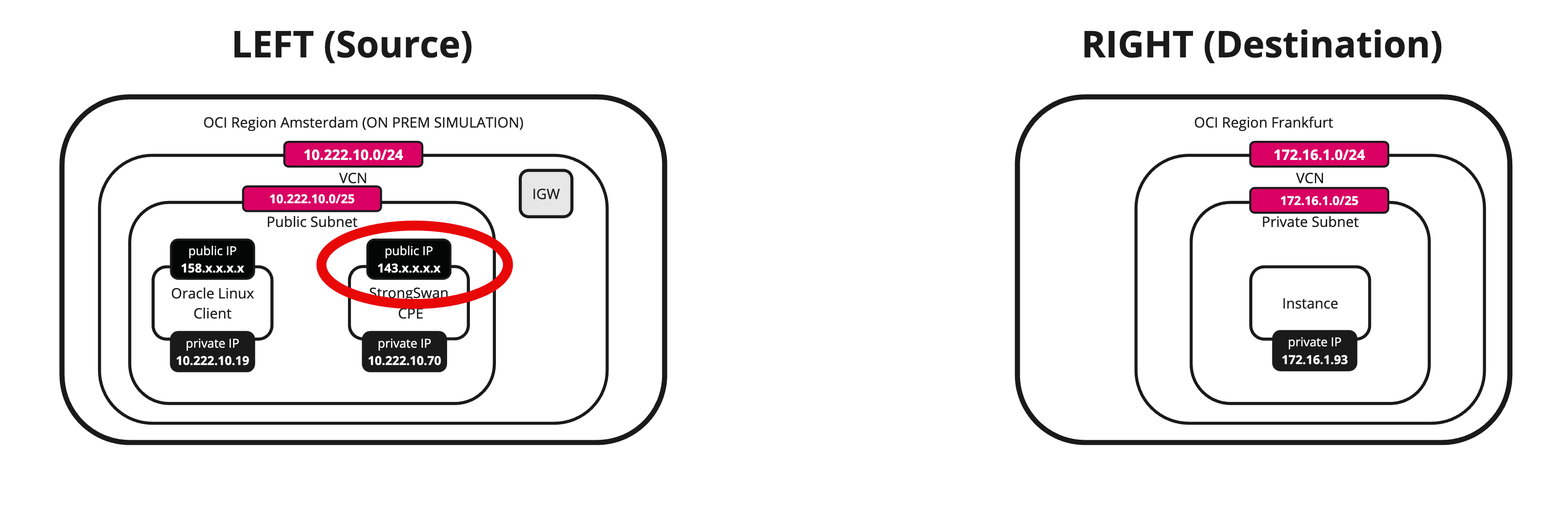
The following image illustrates what we have discussed so far.
Note: Note that the Libreswan CPE is not on this image yet.
-
Task 1: Review the Destination OCI Region (VCN, Subnet, DRG, VCN Attachments and Instances)
In this task, we will check what we have in place to get started.
-
VCN
-
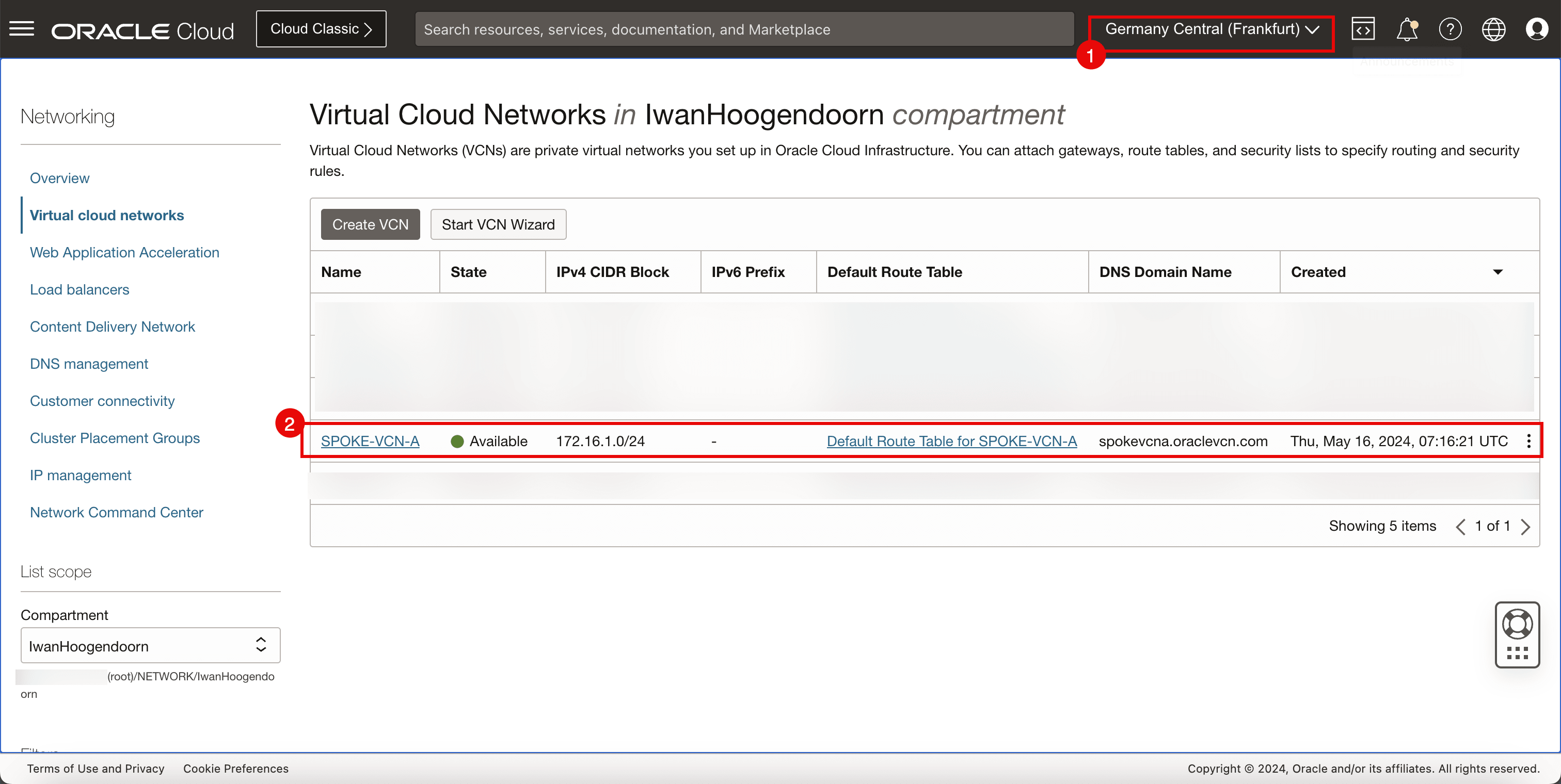
Review the destination OCI region. For this tutorial, it is Germany Central (Frankfurt) OCI region.
-
Review the VCN, subnet and instance.
-
-
Subnets
-
Review the private subnet to which instances will be attached.
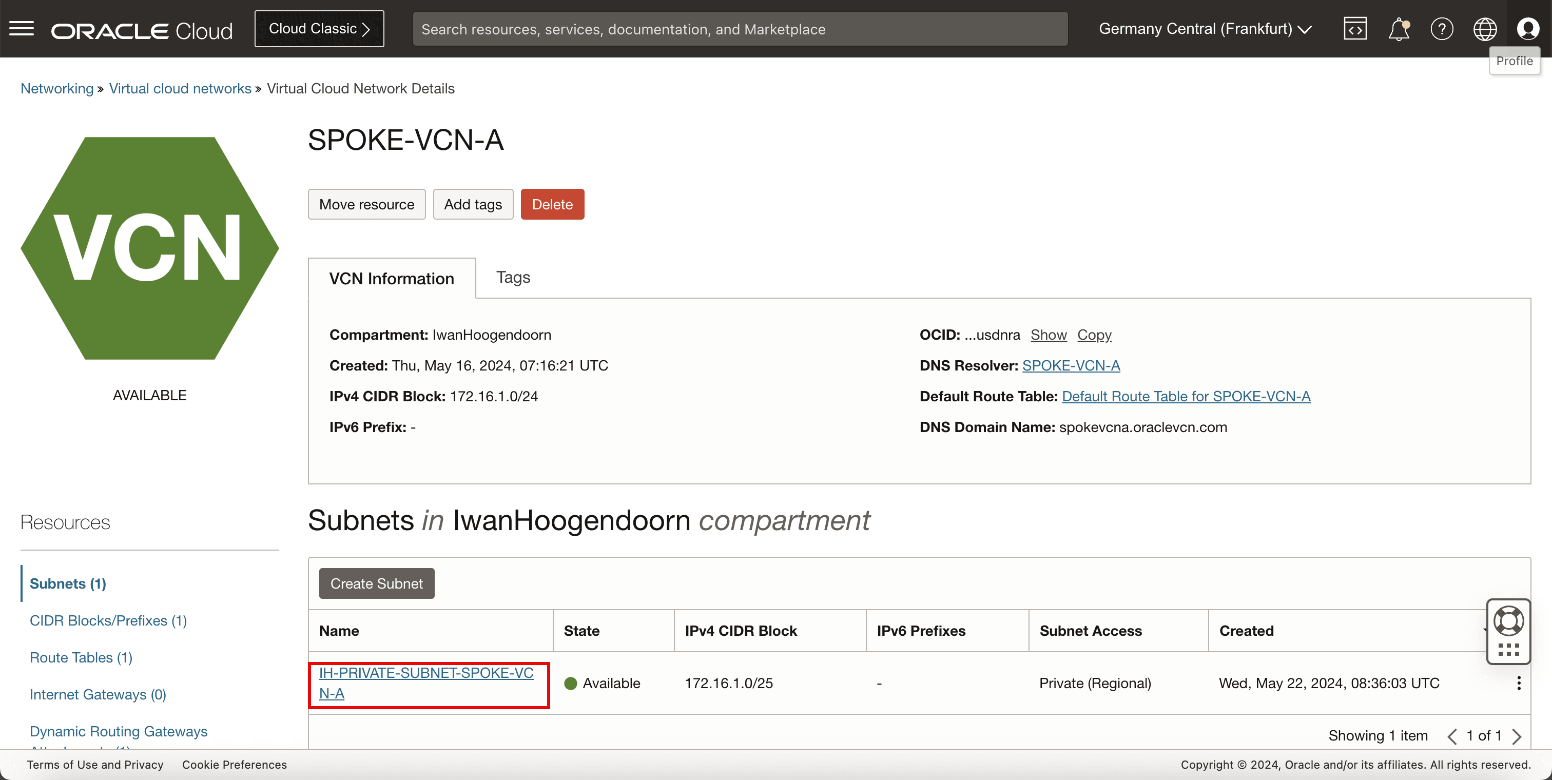
-
-
DRG
-
Review the DRG that will be used as a VPN endpoint to terminate the VPN.
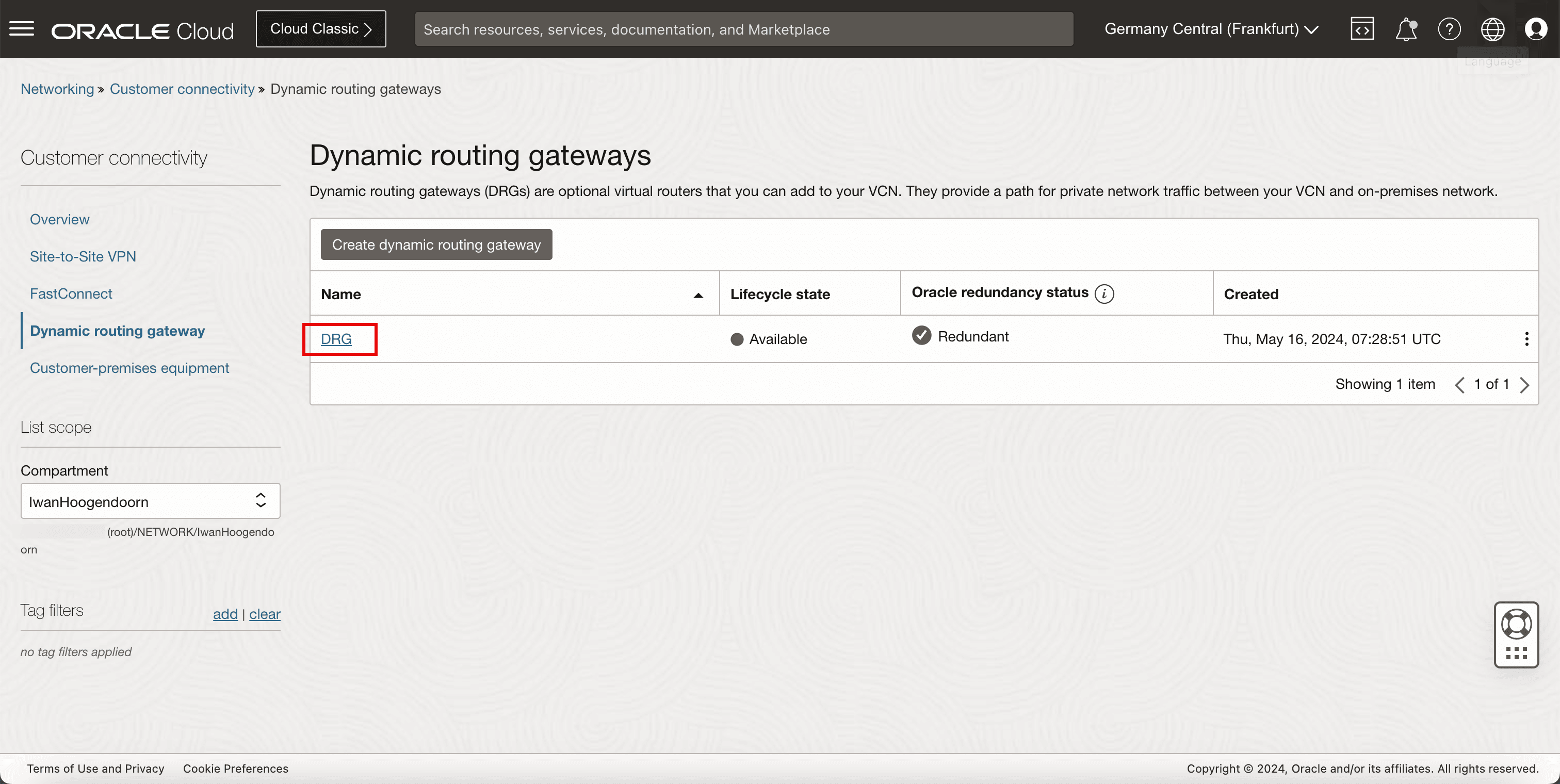
-
-
VCN Attachment
-
Review the VCN attachment, to make sure the VCN is attached to the DRG so that the DRG can route VPN traffic to the correct VCN, subnet, and instance.
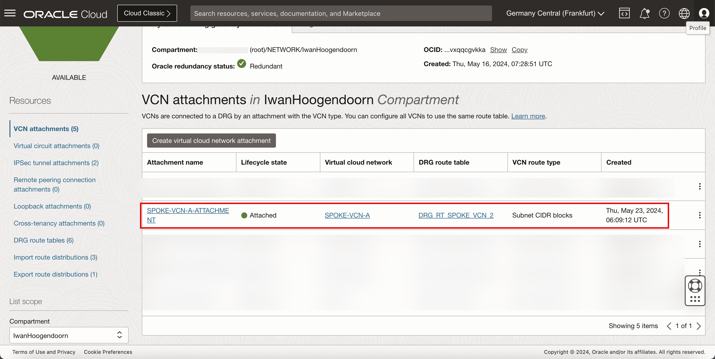
-
-
Instance
-
Review the instance that we will use as a network endpoint to perform our network tests.
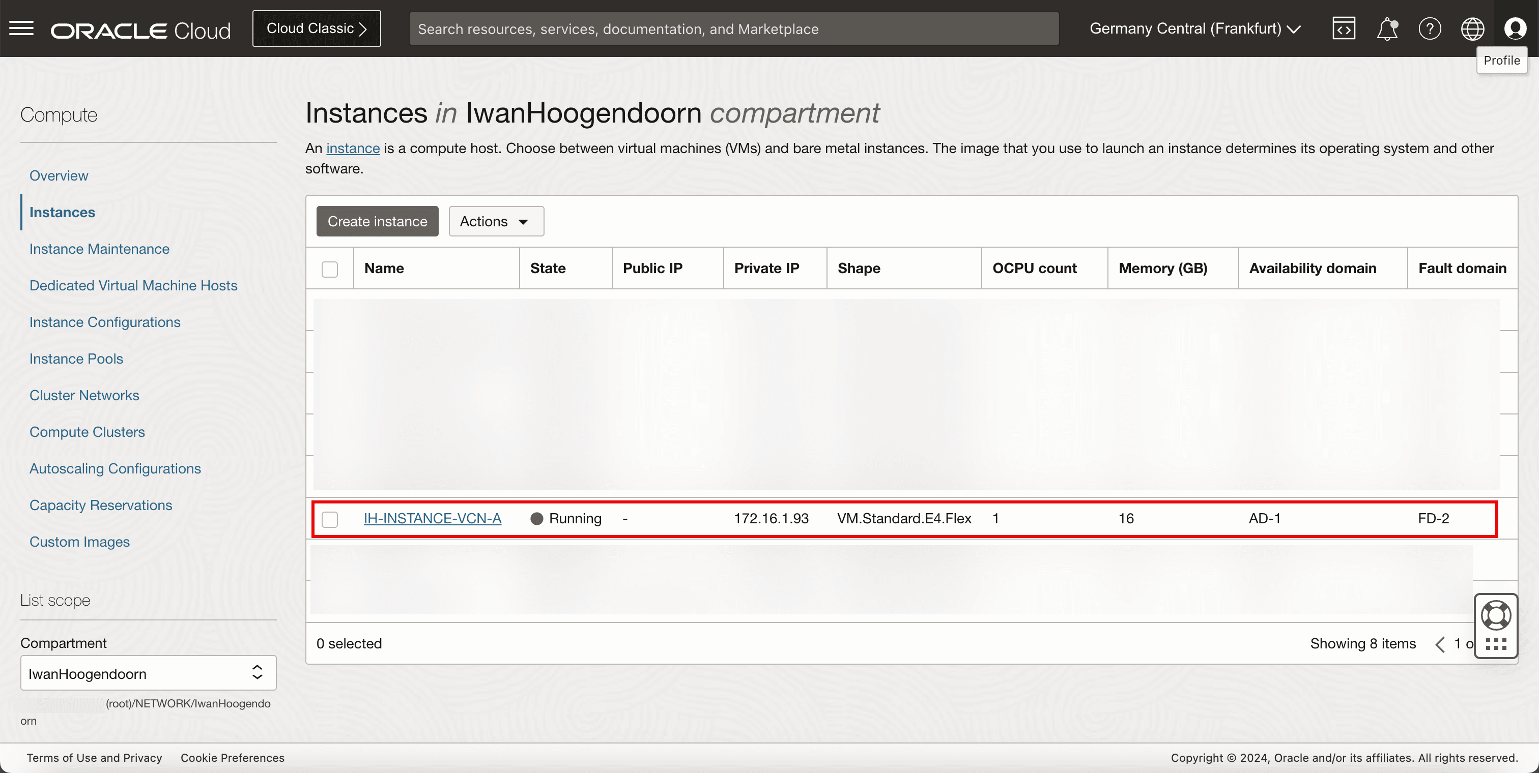
-
The following image illustrates what we have created so far.
Task 2: Review the Source OCI Region (VCN, Public Subnet, Internet Gateway, and Instances)
-
VCN
-
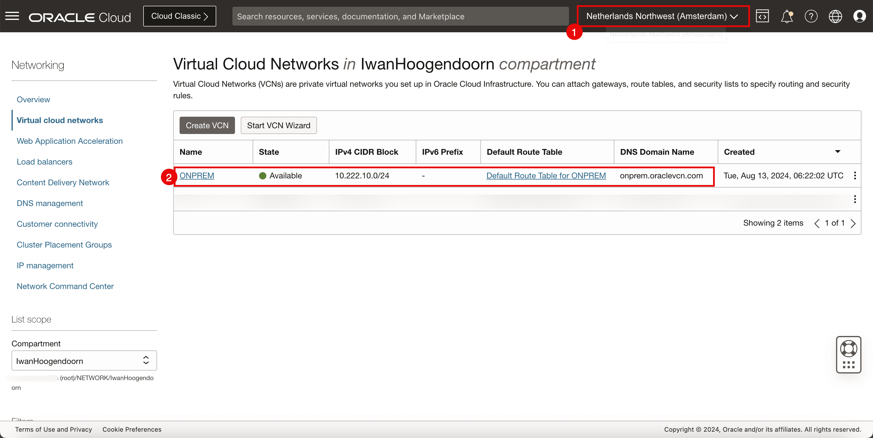
Review the source OCI region. For this tutorial, it is Netherlands Northwest (Amsterdam) OCI region.
-
Review the VCN, subnet and instance.
-
-
Public Subnet
-
Review the public subnet to which instances and the Libreswan VPN endpoint will be attached.
-
Review the default route table for the VCN.
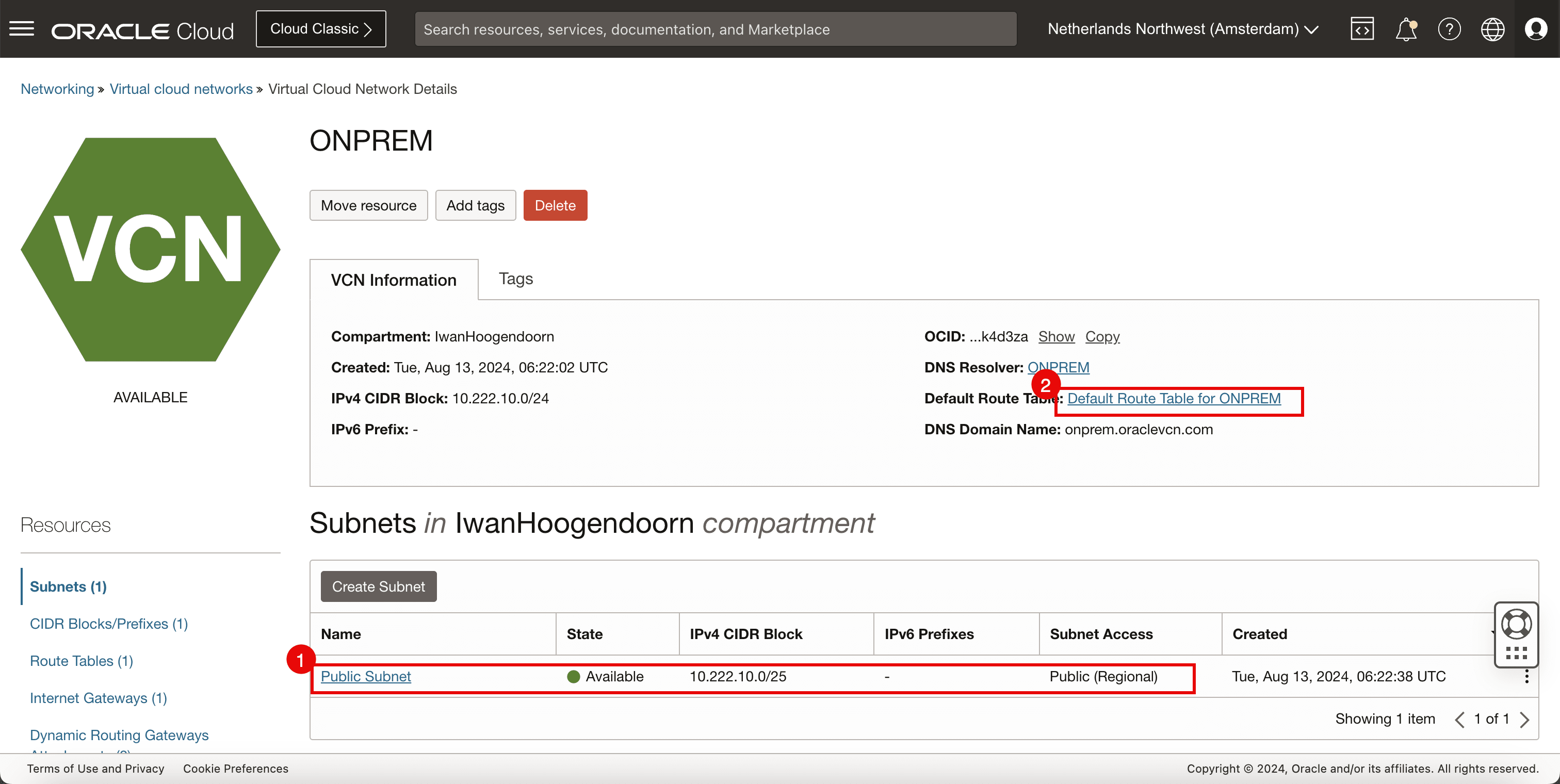
Note: We need to have a public subnet here, as we need to make sure that the Libreswan VPN endpoint can communicate to the internet to set up the VPN connection with the other side.
-
-
Internet Gateway
-
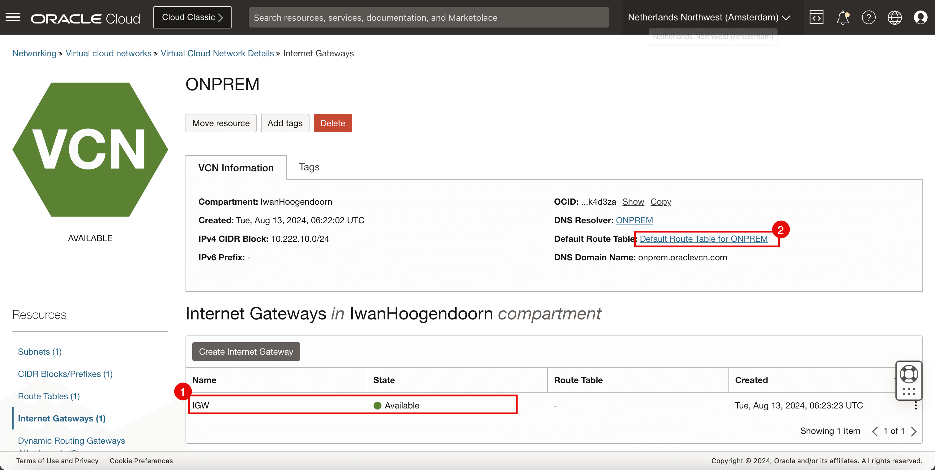
Review the internet gateway to allow internet connectivity
-
Review the default route table for the VCN.
-
-
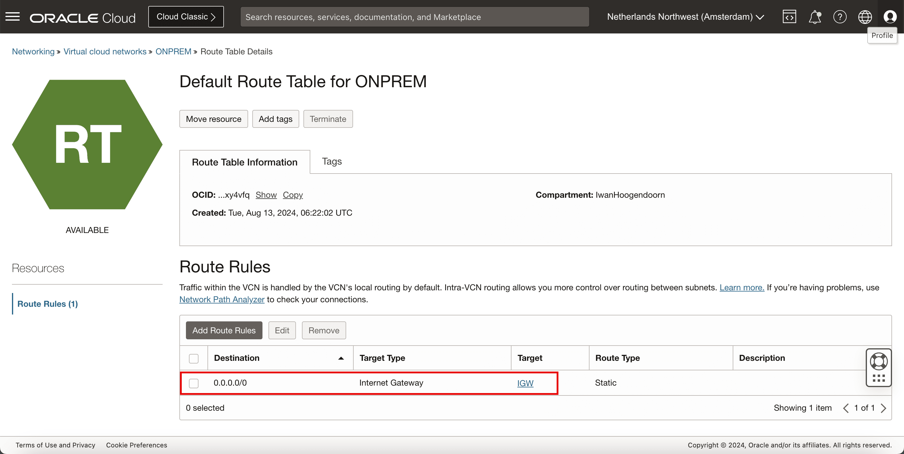
Route Table
-
Review the VCN route table, and make sure all traffic is routed to the internet gateway.
-
-
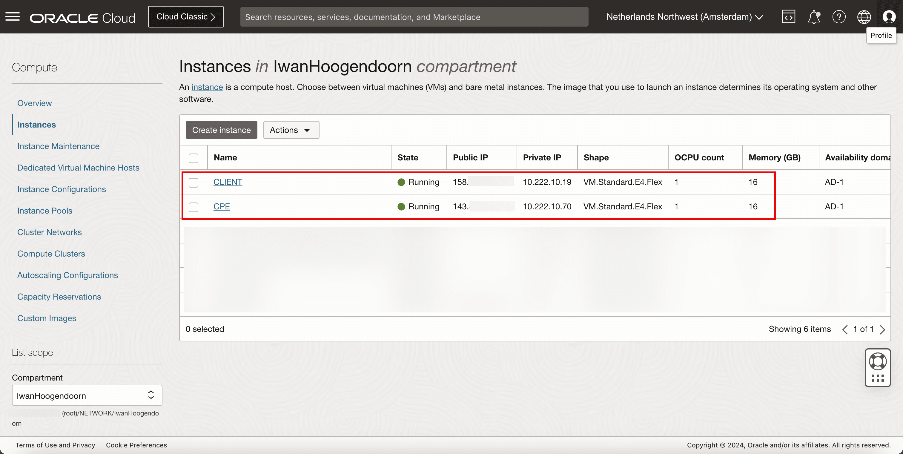
Instances
-
Review the instance to use as a network endpoint to perform our network tests.
-
For both CLIENT and CPE we have used Oracle Linux 8 as the main Operating System.
-
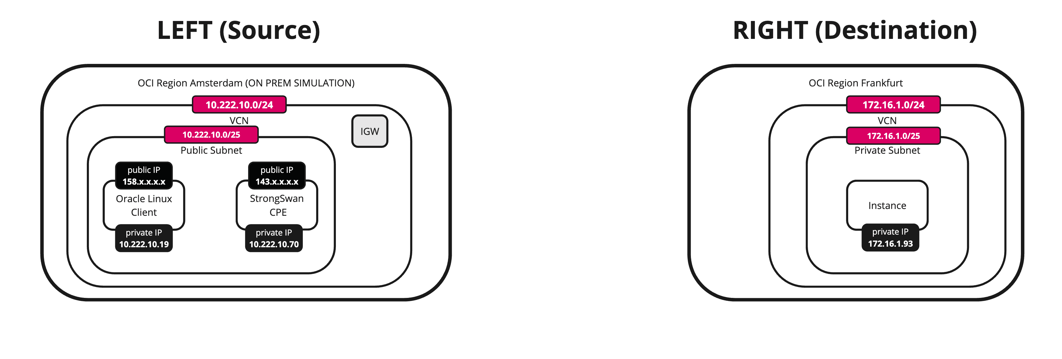
The following image illustrates what we have created so far.
Task 3: Collect the Public IP Address of the CPE Instance from the Source OCI Region
-
Go to the OCI Console.
-
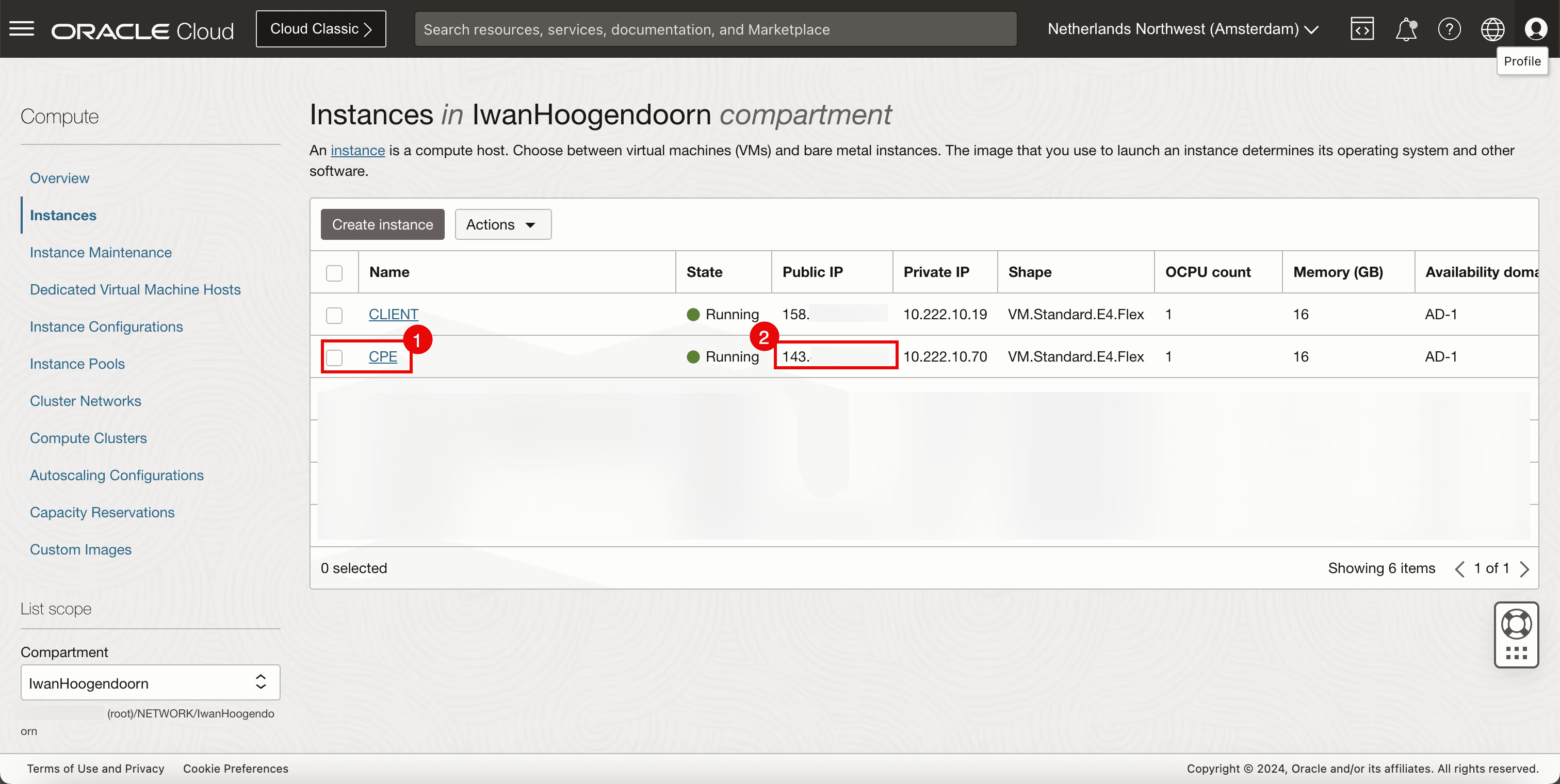
In the source OCI region we have deployed an instance that will be responsible for the VPN termination (VPN endpoint).
-
Collect the public IP address that is configured on this VPN endpoint. For this tutorial, this public IP address starts with 143.
-
-
The following image illustrates what we have created so far.
Task 4: Create a new CPE in the Destination OCI Region
-
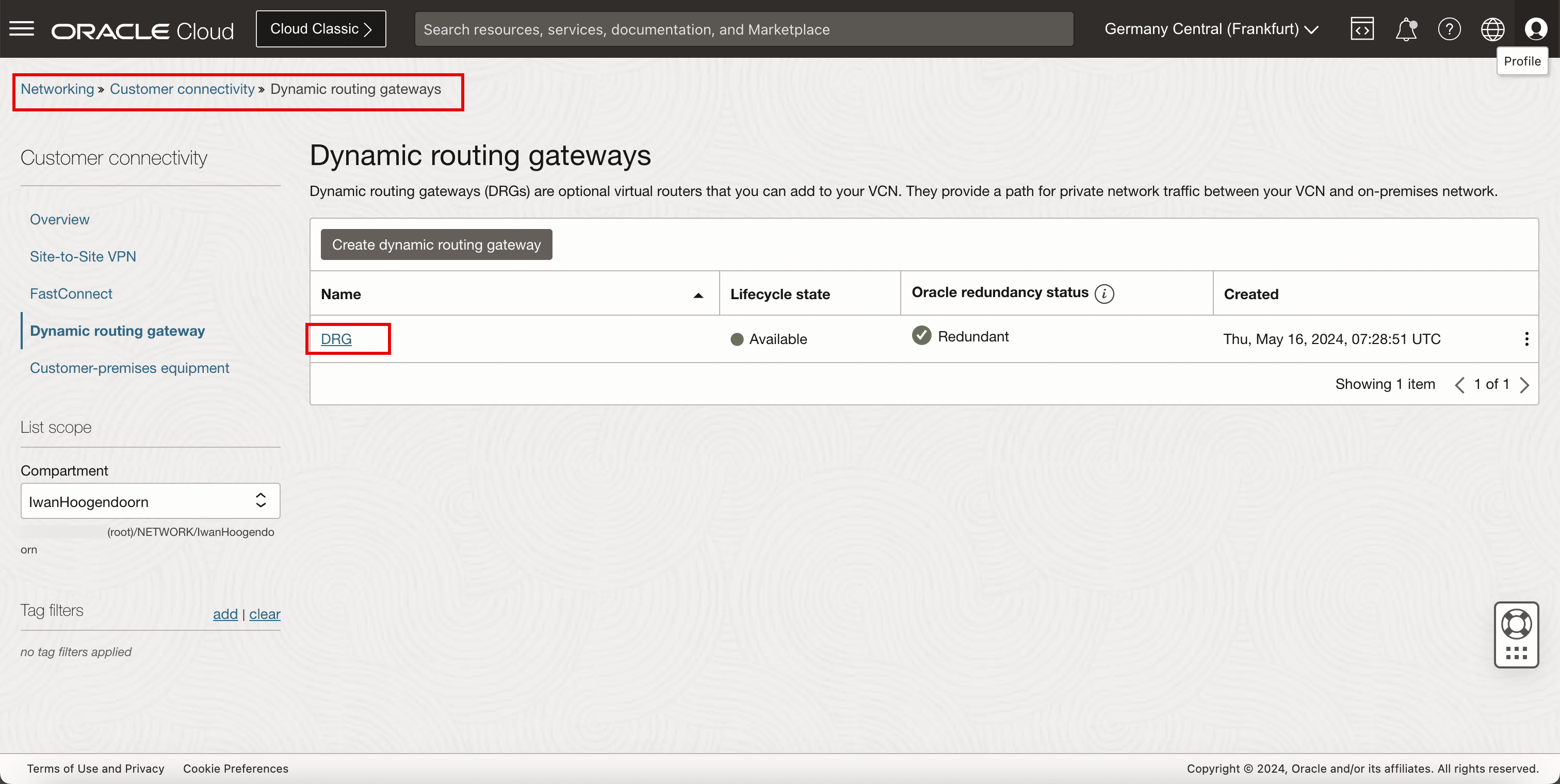
Go to the OCI Console, navigate to Networking, Customer Connectivity, Dynamic routing gateway and click the DRG.
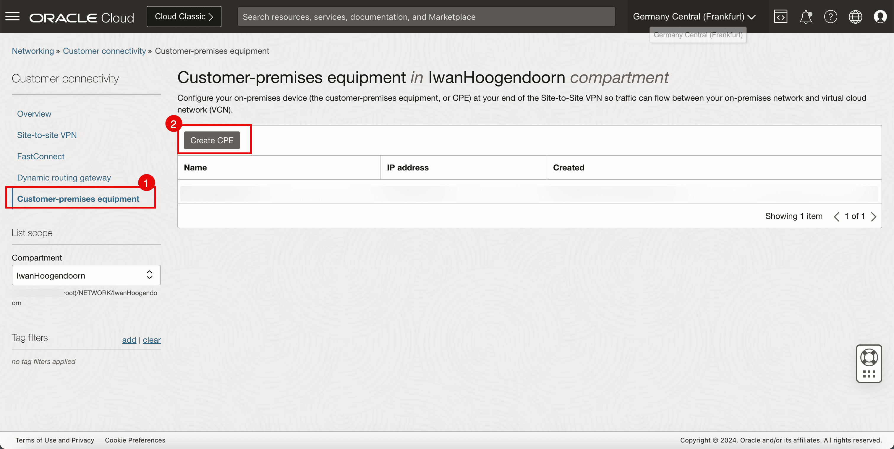
- Click Customer premises equipment.
- Click Create CPE.
-
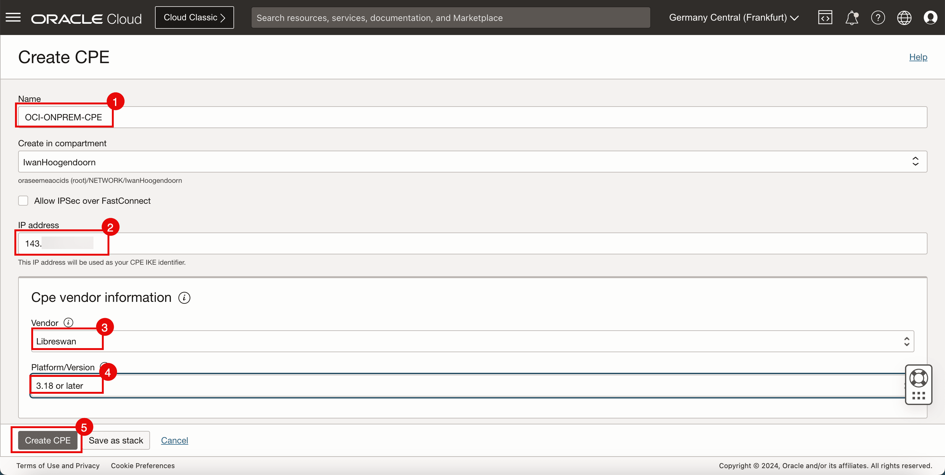
Enter the following information.
- Name: Enter a name for the CPE.
- Public IP address: Enter public IP address collected in Task 3.
- Vendor: Select Libreswan.
- Platform/Version: Select the CPE platform version.
- Click Create CPE.
- Note that the CPE is now created.
- Note the public IP address of the CPE.
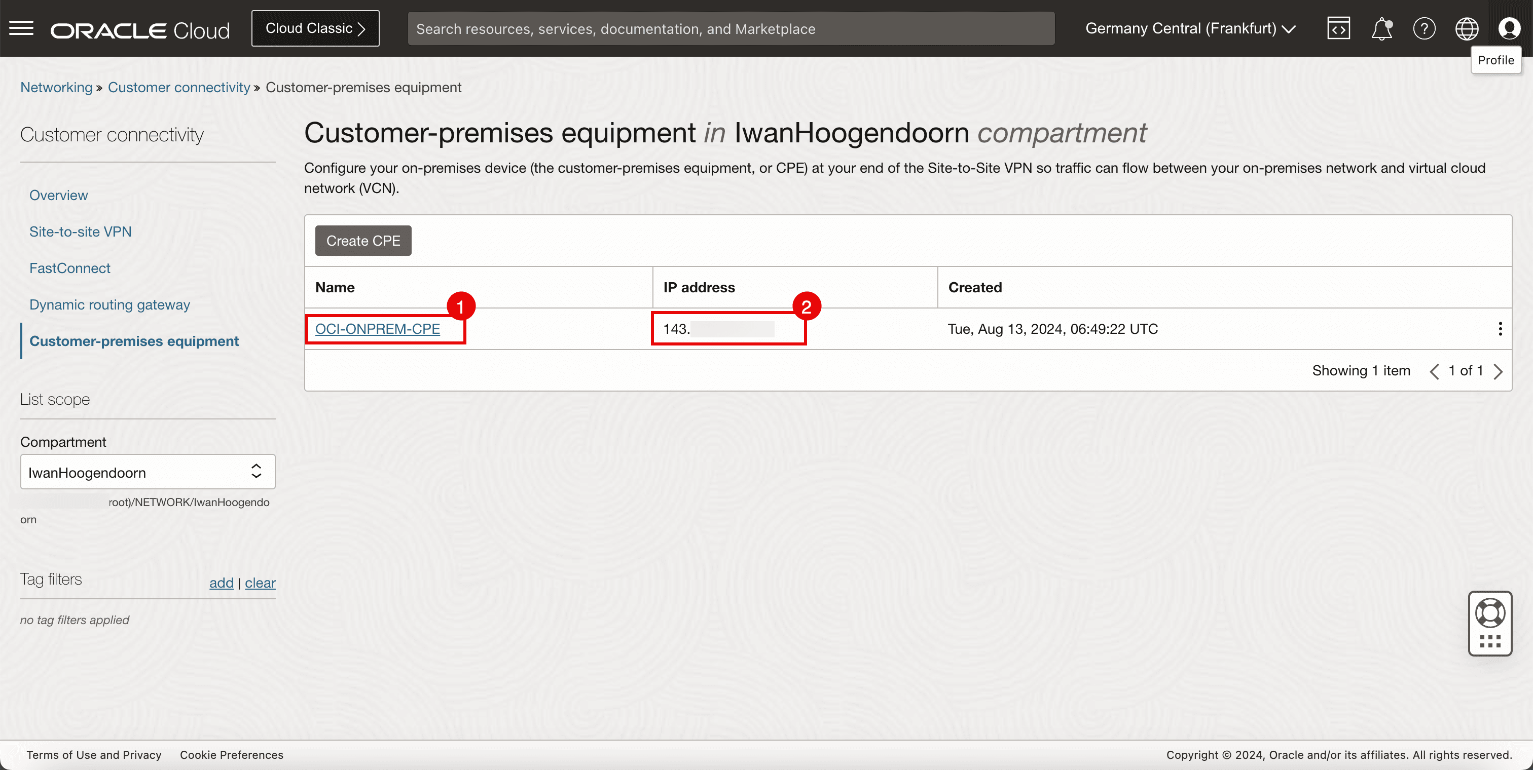
Task 5: Configure the OCI Site-to-Site VPN in the Destination OCI Region
-
Go to the OCI Console.
- Click Site-to-Site VPN.
- Click Create IPSec connection.
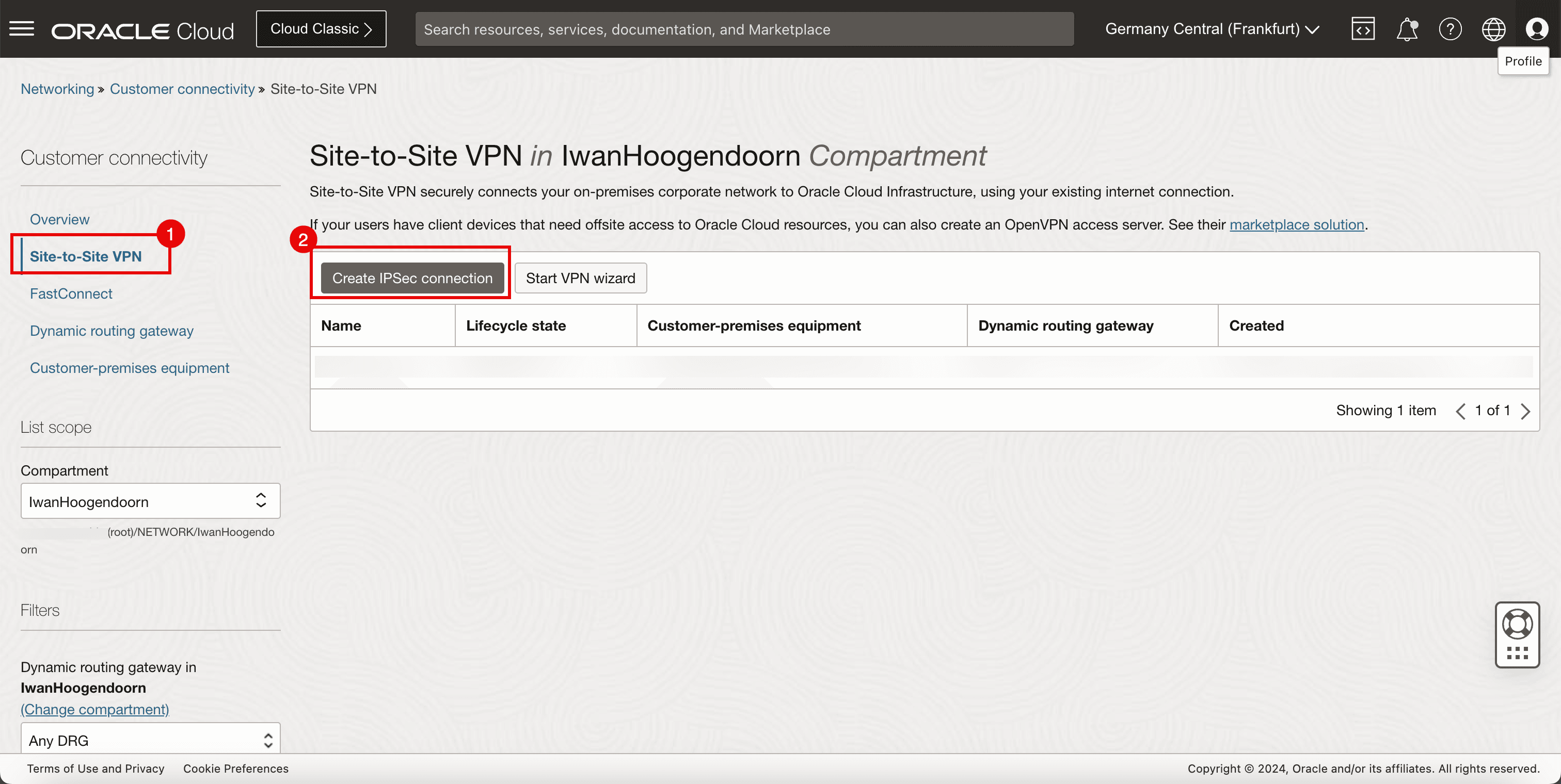
-
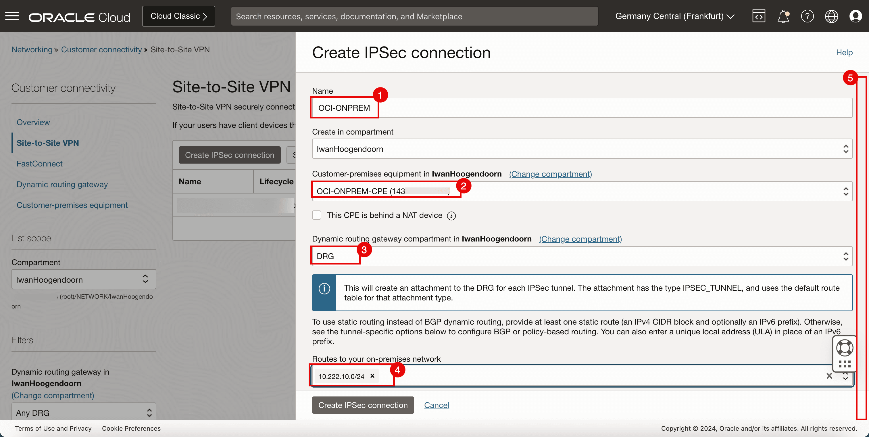
In the Create IPSec connection page, enter the following information.
- Name: Enter a name for the IPSec connection.
- Customer-premises equipment: Select the CPE created in Task 4.
- Dynamic routing gateway: Select the DRG.
- Routes to your on-premises network: Enter the Remote network that you want to route through the IPSec connection. For this tutorial, it is
10.222.10.0/24network. - Scroll down.
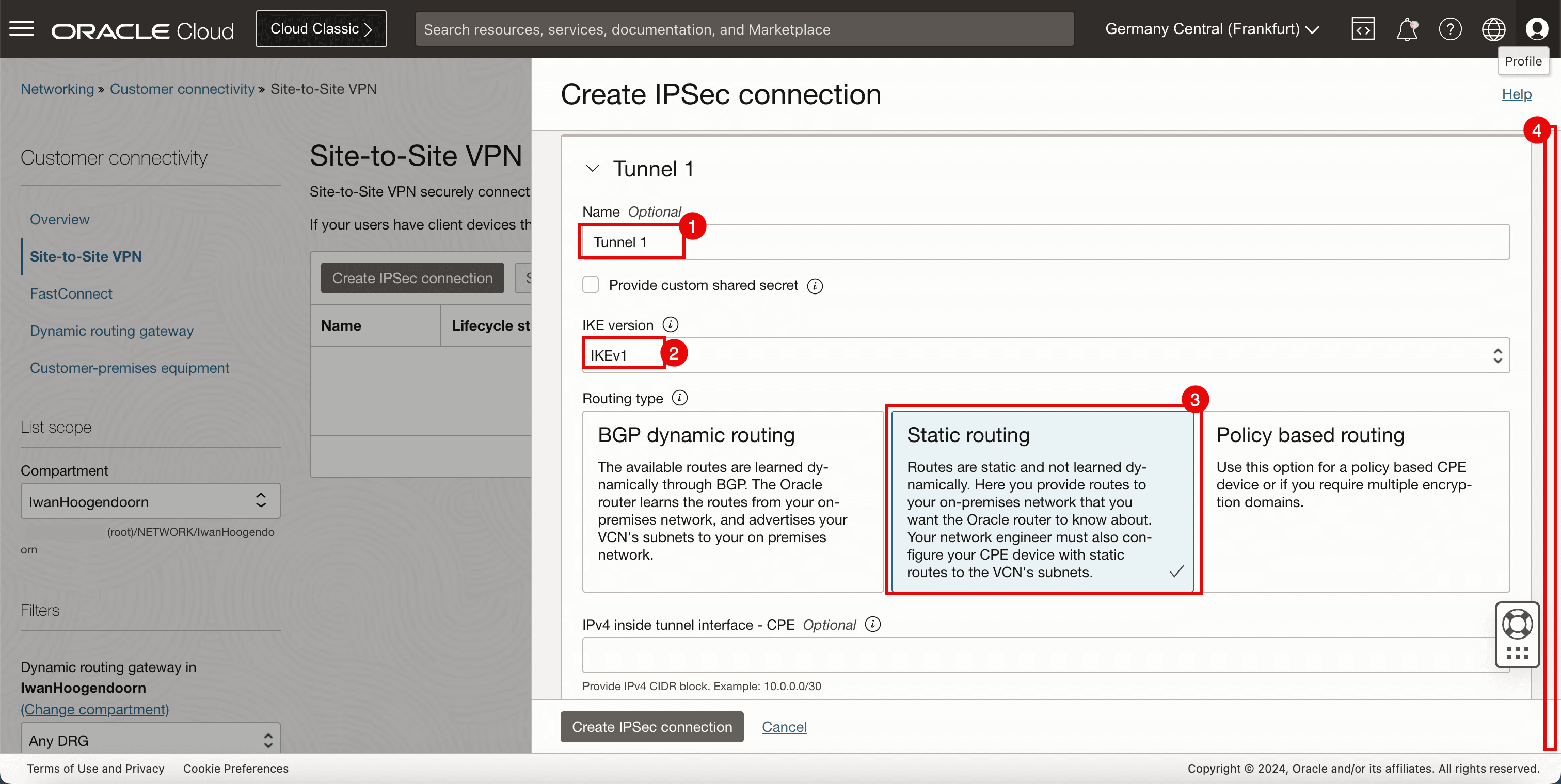
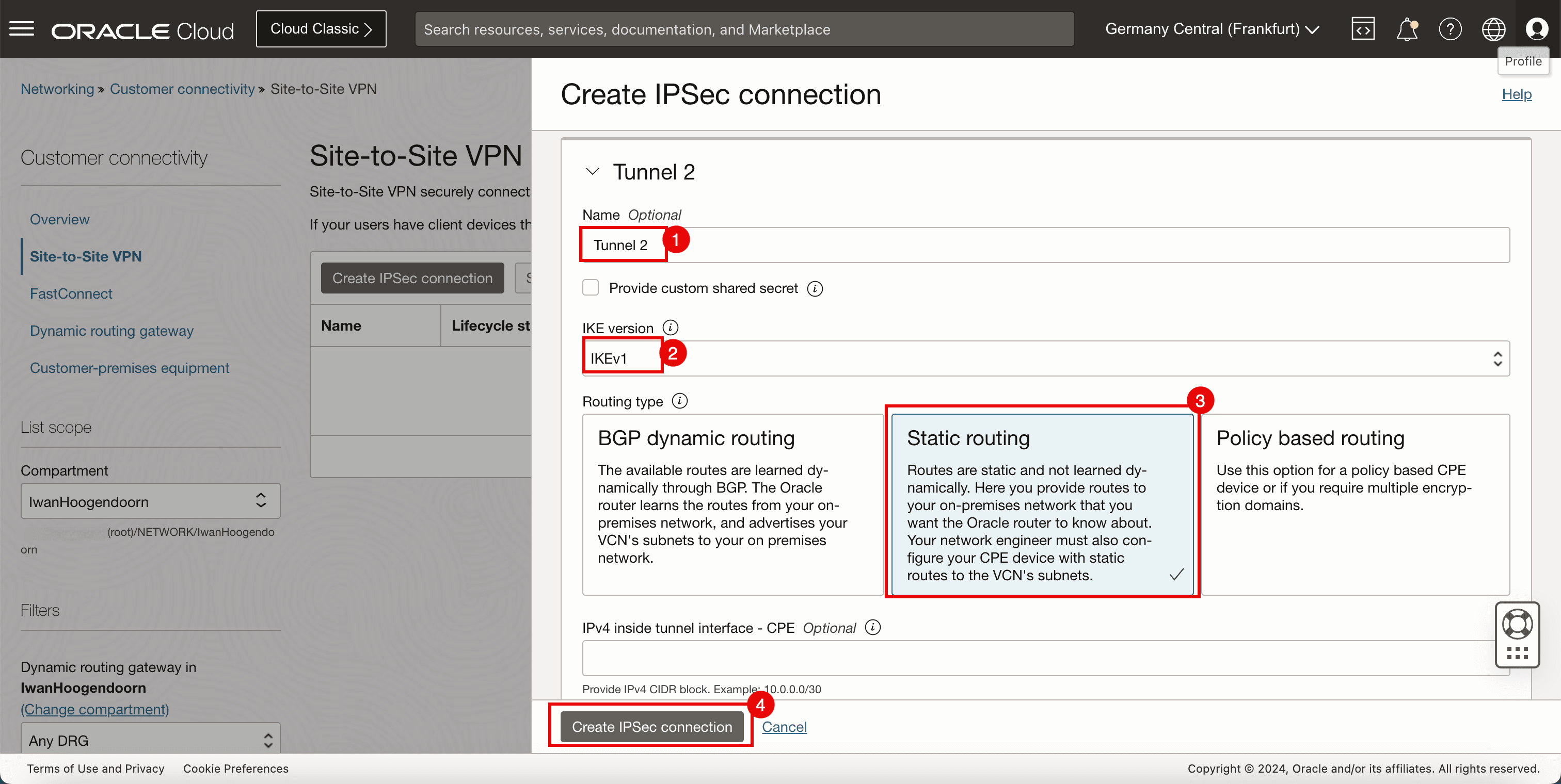
- Name: Enter a name for the first tunnel.
- IKE version: Enter the IKE version to be IKEv1.
- Routing type: Select Static Routing.
- Scroll down.
- Name: Enter a name for the second tunnel.
- IKE version: Enter the IKE version to be IKEv1.
- Routing type: Select Static Routing.
- Click Create IPSec connection.
Task 6: Collect the Public IP Address of the IPSec Tunnels in the Destination OCI Region and Download the CPE Configuration
-
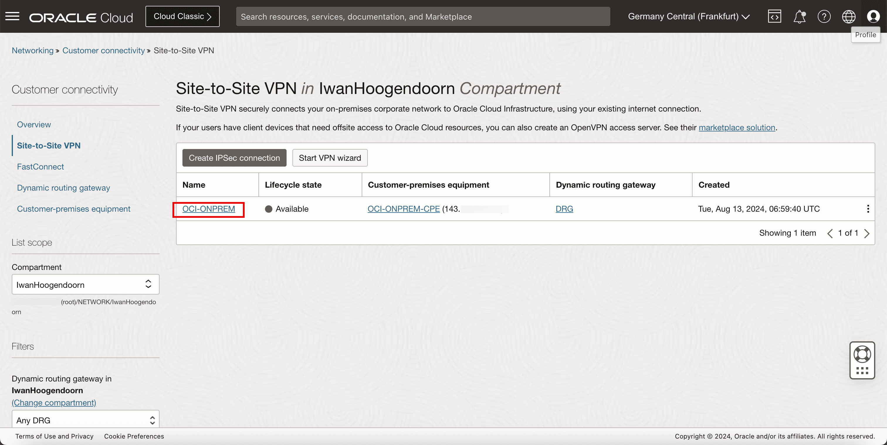
The IPSec connection is created, the public IP addresses for both IPSec tunnels will be available and we will need to configure the other side of the VPN.
-
Click the Site-to-Site VPN created in Task 5.
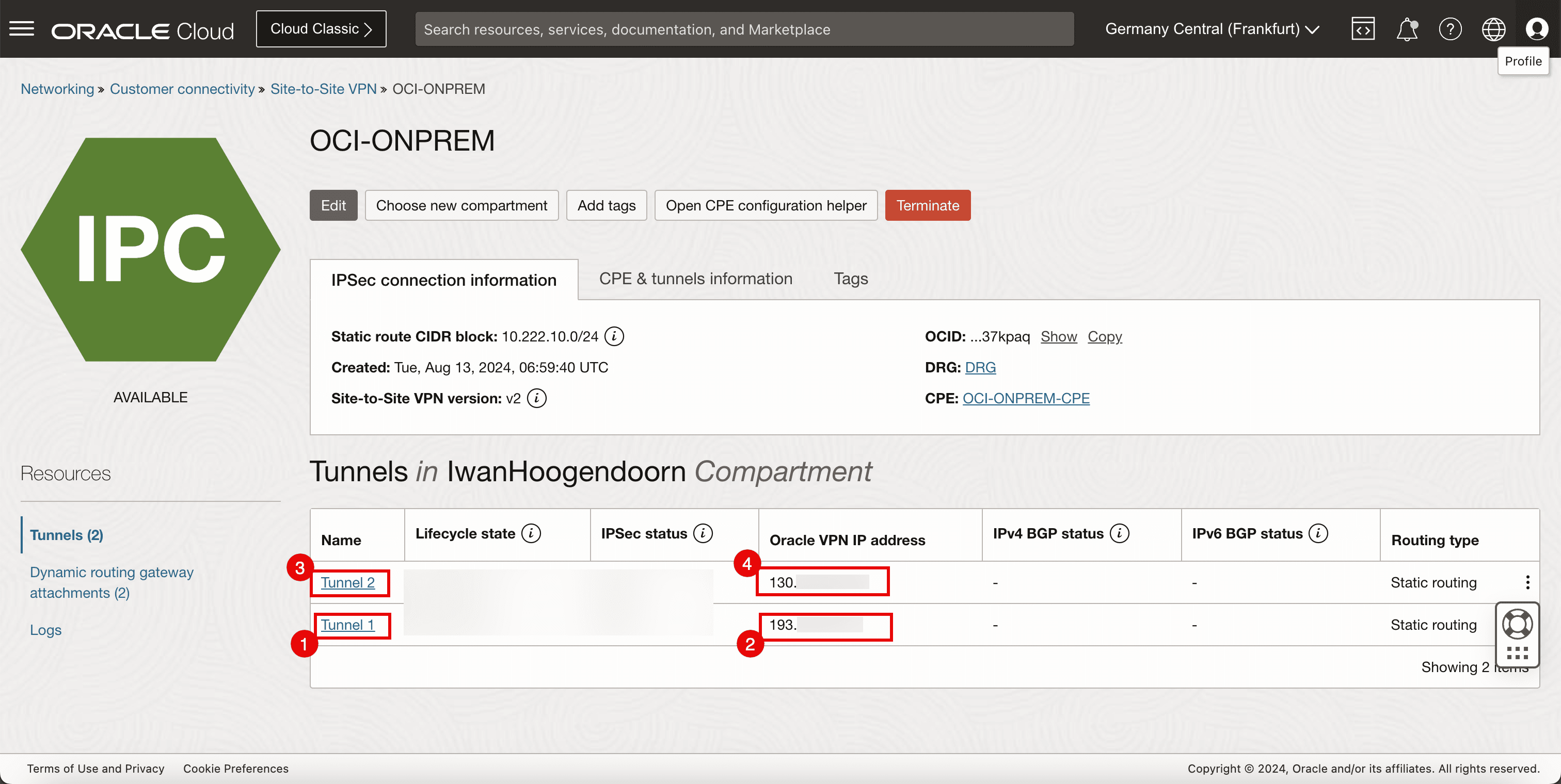
- Note Tunnel 1 of the IPSec connection.
- Note down the public IP address for tunnel 1. For this tutorial, this IP address starts with 193.
- Note Tunnel 2 of the IPSec connection.
- Note down the public IP address for tunnel 2. For this tutorial, this IP address starts with 130.
-
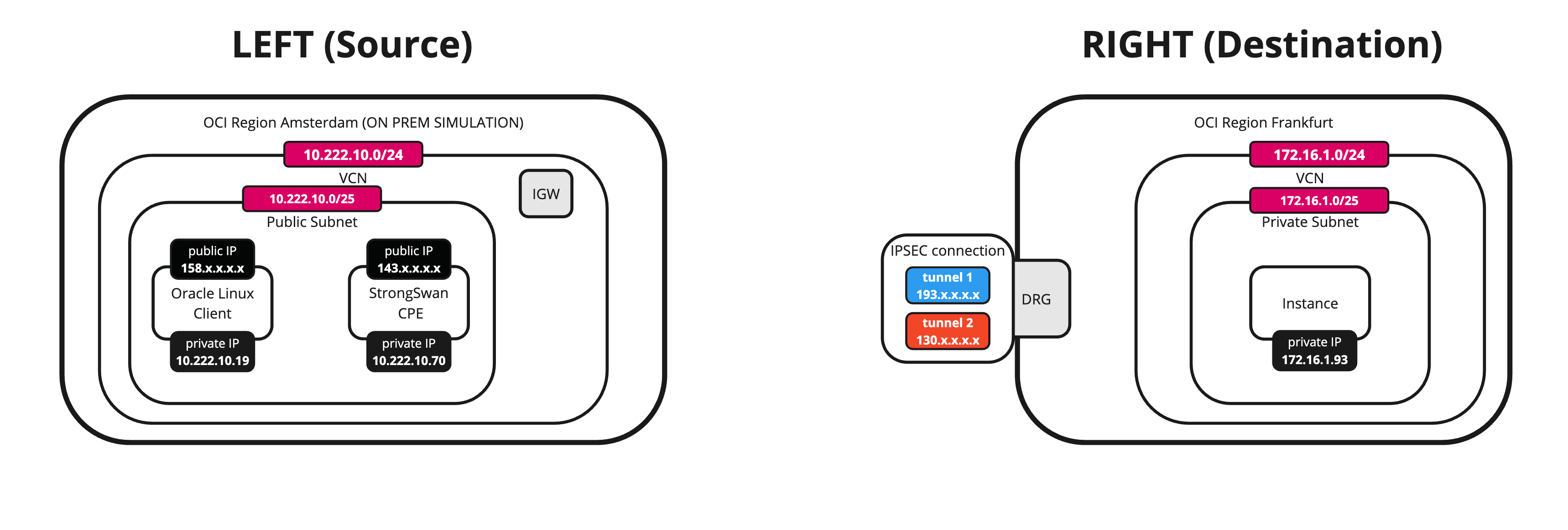
The following image illustrates what we have created so far.
Task 7: Configure the CPE Instance in the Source OCI Region and Install and Configure Libreswan
-
Configure the CPE instance.
- Set up an SSH session for the CPE located in the source OCI region or VCN.
- Make sure you are logged in.

-
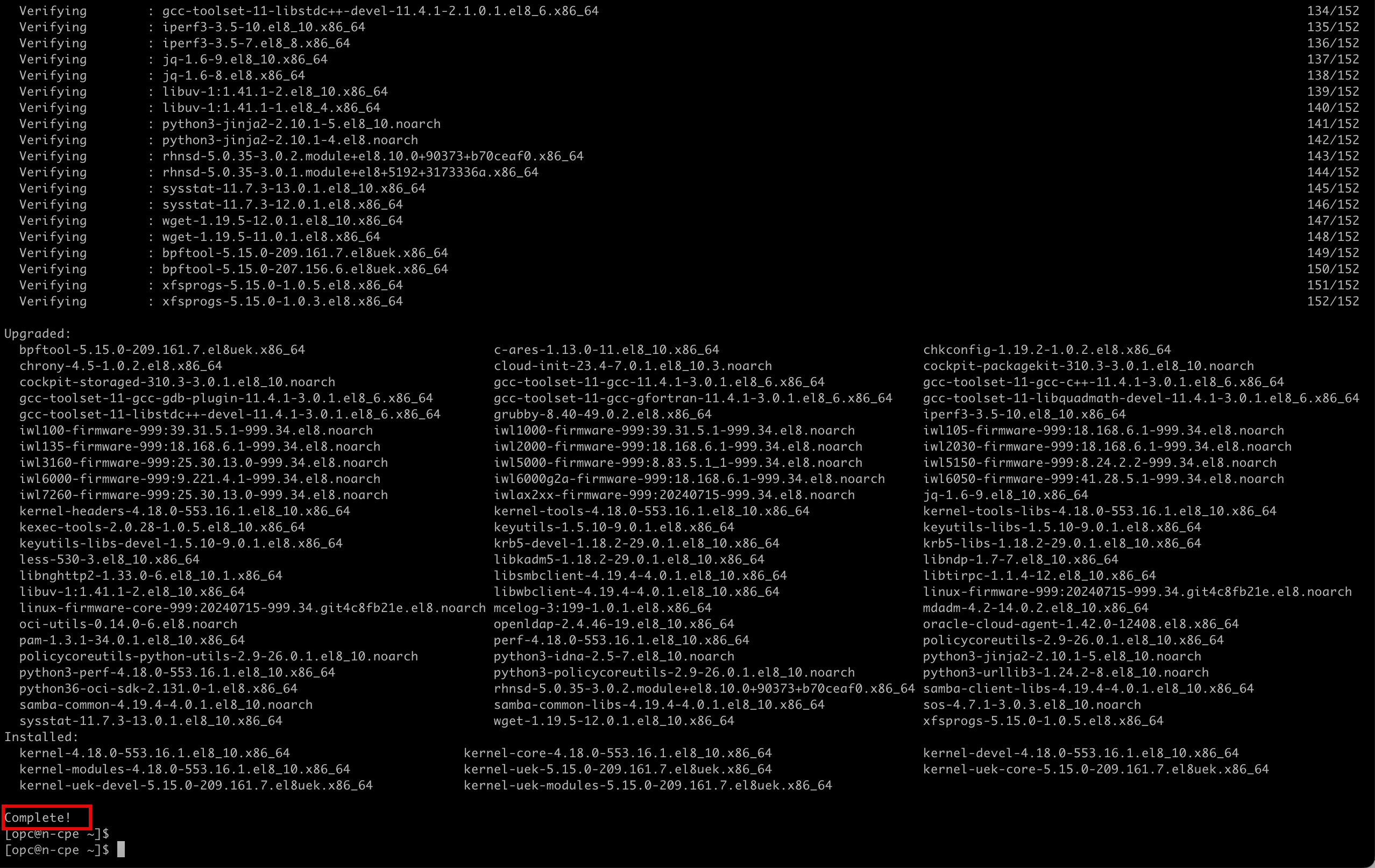
Run the following command to upgrade the software.
[opc@cpe ~]$ sudo dnf upgrade -y
-
Make sure the upgrade is successfully completed.
-
Run the following command to run the command where higher privileges are required.
[opc@cpe ~] sudo su
-
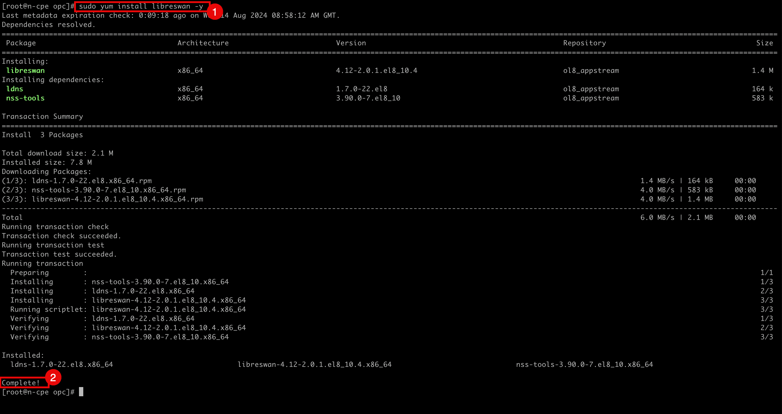
Run the following command to install the Libreswan software.
[root@cpe opc]# sudo yum install libreswan -y -
Note that the software is successfully installed.
-
-
Edit the following file to enable IP forwarding.
[root@cpe etc]# nano /etc/sysctl.conf
-
Make sure the
/etc/sysctl.conffile contains the following content.kernel.unknown_nmi_panic = 1 net.ipv4.ip_forward = 1 net.ipv4.conf.all.accept_redirects = 0 net.ipv4.conf.all.send_redirects = 0 net.ipv4.conf.default.send_redirects = 0 net.ipv4.conf.ens3.send_redirects = 0 net.ipv4.conf.default.accept_redirects = 0 net.ipv4.conf.ens3.accept_redirects = 0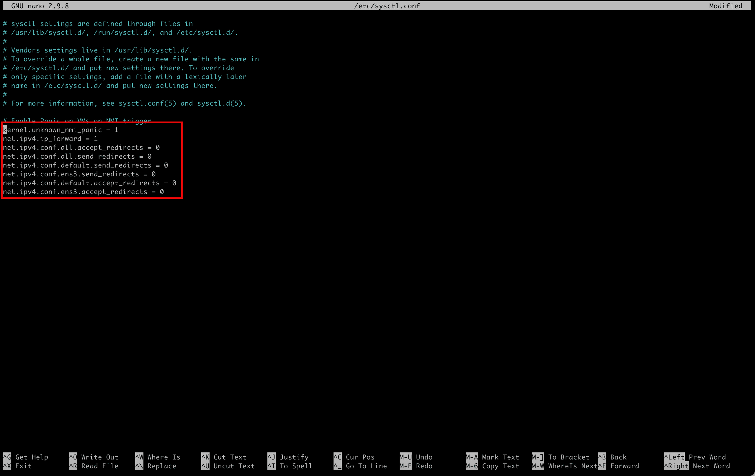
-
Save the file using
Ctrl + Xand enterY.-
Run the following command to verify the content of the file.
[root@cpe opc]# more /etc/sysctl.conf -
Note the output will be the same as the content of the file.

-
-
Run the following command to reload and apply the file to enable forwarding.
[root@cpe etc]# sudo sysctl -p
-
Run the following command to verify if IP forwarding is enabled.
cat /proc/sys/net/ipv4/ip_forward -
Note that the returned value id is
1this means that IP forwarding is enabled and0means that IP forwarding is disabled.

-
Run the following command to change the directory where you need to configure the IPSec tunnels.
[root@cpe opc]# cd /etc/ipsec.d/ -
Create and edit the following file (
tunnel1.conf) to configure the first IPSec tunnel in tunnel 1.[root@cpe ipsec.d]# nano /etc/ipsec.d/tunnel1.conf

-
-
Make sure the
/etc/ipsec.d/tunnel1.conffile contains the following content.conn tunnel1 keyexchange=ike pfs=yes ikev2=no ike=aes256-sha2_256;modp1536 phase2alg=aes256-sha1;modp1536 left=10.222.10.70 leftid=143.xxx.xxx.xxx right=193.xxx.xxx.xxx rightid= 193.xxx.xxx.xxx authby=secret leftsubnet=0.0.0.0/0 rightsubnet=0.0.0.0/0 auto=start mark=5/0xffffffff vti-interface=vti1 vti-routing=no encapsulation=auto ikelifetime=28800s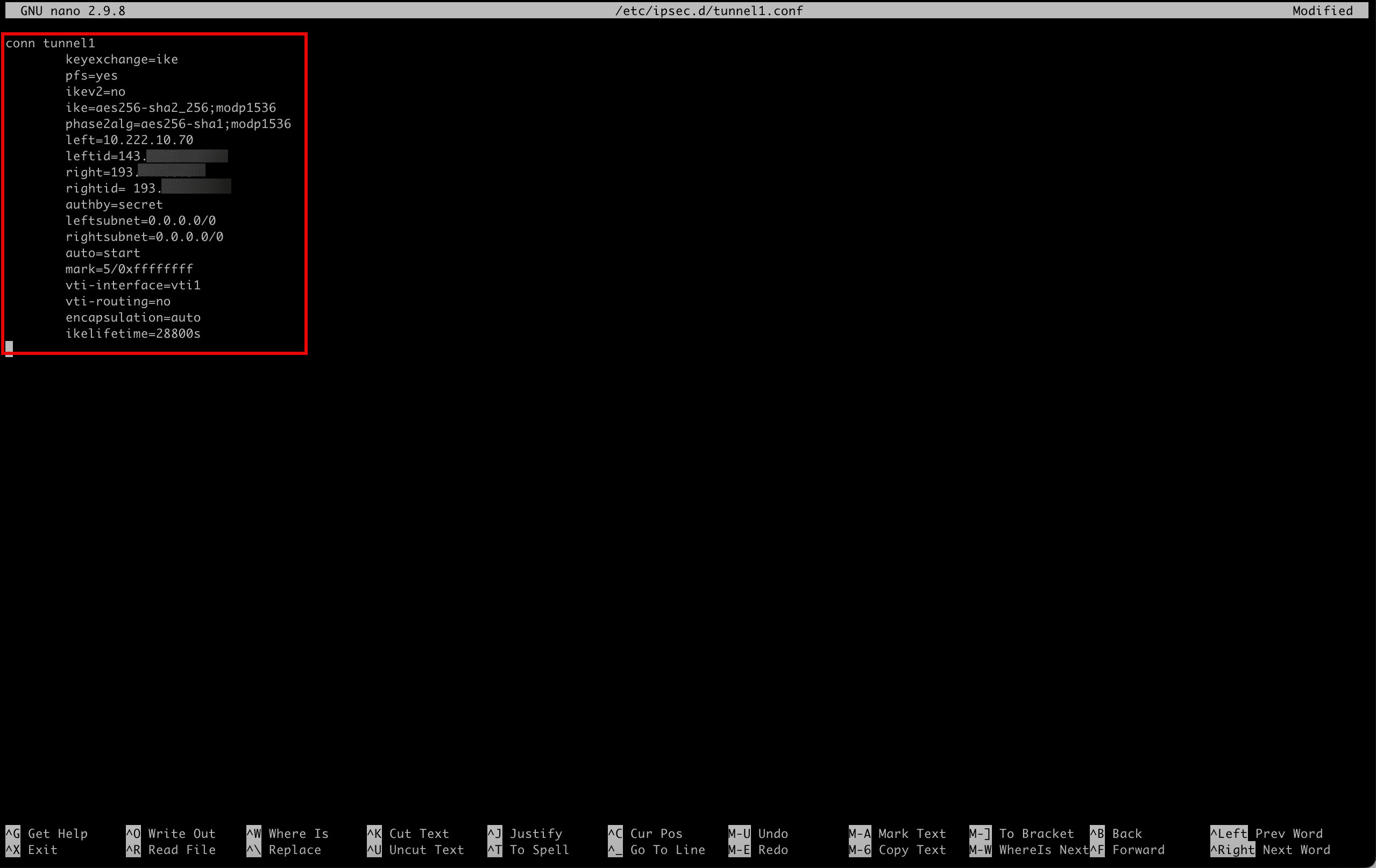
-
Save the file using
Ctrl + Xand enterY. -
Create and edit the following file (
tunnel2.conf) to configure the second IPSec tunnel intunnel2.[root@cpe ipsec.d]# nano /etc/ipsec.d/tunnel2.conf
-
Make sure the
/etc/ipsec.d/tunnel2.conffile contains the following content.conn tunnel2 keyexchange=ike pfs=yes ikev2=no ike=aes256-sha2_256;modp1536 phase2alg=aes256-sha1;modp1536 left=10.222.10.70 leftid=143.xxx.xxx.xxx right=130.xxx.xxx.xxx rightid=130.xxx.xxx.xxx authby=secret leftsubnet=0.0.0.0/0 rightsubnet=0.0.0.0/0 auto=start mark=6/0xffffffff vti-interface=vti2 vti-routing=no encapsulation=auto ikelifetime=28800s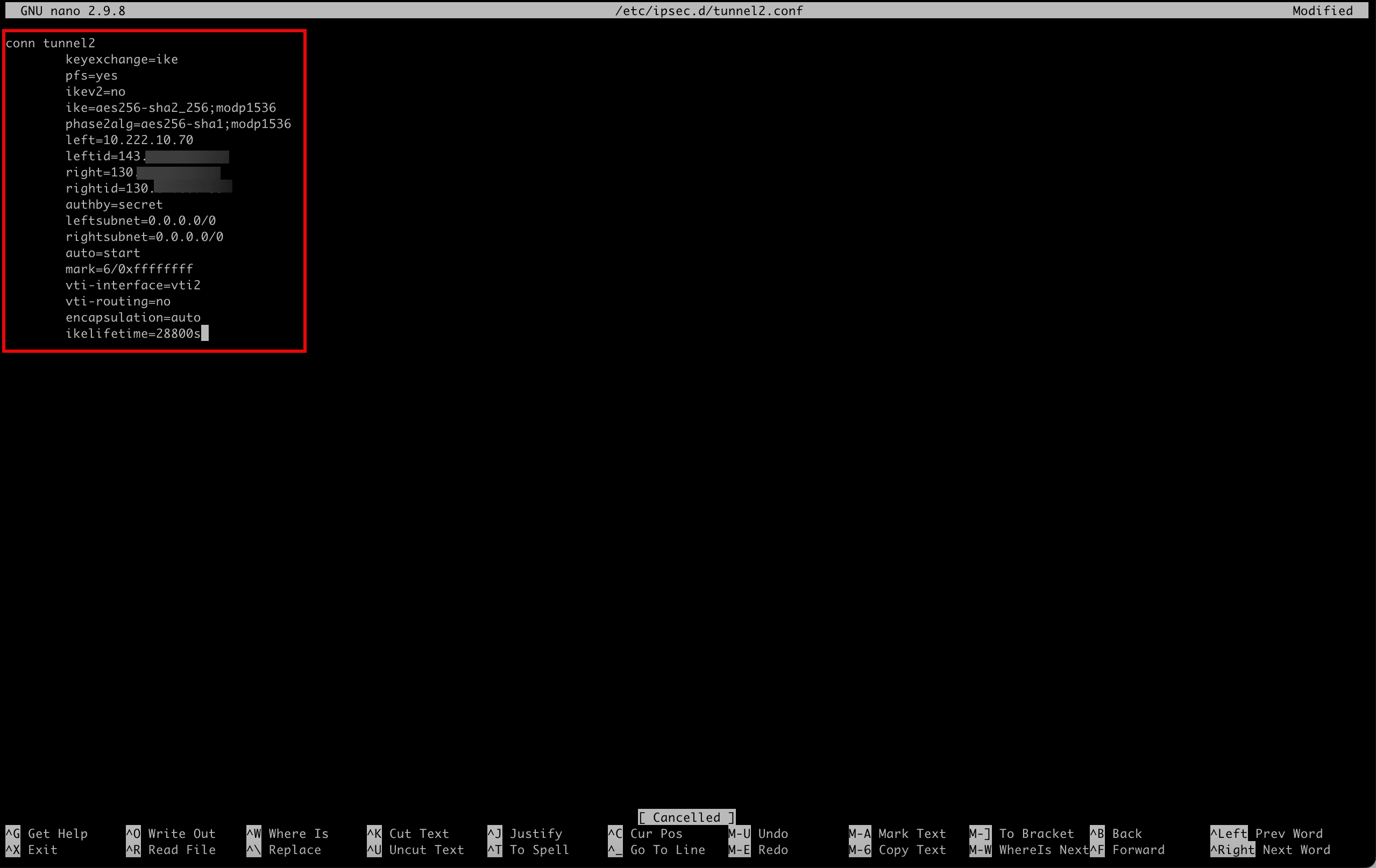
-
Save the file with
Ctrl + Xand enterY.-
Run the following command to verify the content of the file for
tunnel1.[root@cpe ipsec.d]# more /etc/ipsec.d/tunnel1.conf -
Note the output will be the same as the content of the file.
-
Run the following command to verify the content of the file for
tunnel2.[root@cpe ipsec.d]# more /etc/ipsec.d/tunnel2.conf -
Note that the output will be the same as the content of the file.

-
-
We have configured the IPSec tunnels, now we also need to configure the shared secrets as we are using a secret key for authentication.
When we created the OCI Site-to-Site VPN in Task 5, the tunnels were created and in this process, OCI also generated the shared secret keys per tunnel. To get and configure them in Libreswan to match the same shared secret, we need to go back to the OCI Console.
- Go to the OCI Console, navigate to Networking, Customer Connectivity, Site-to-Site VPN and click the configured VPN.
- Click the first tunnel configuration.
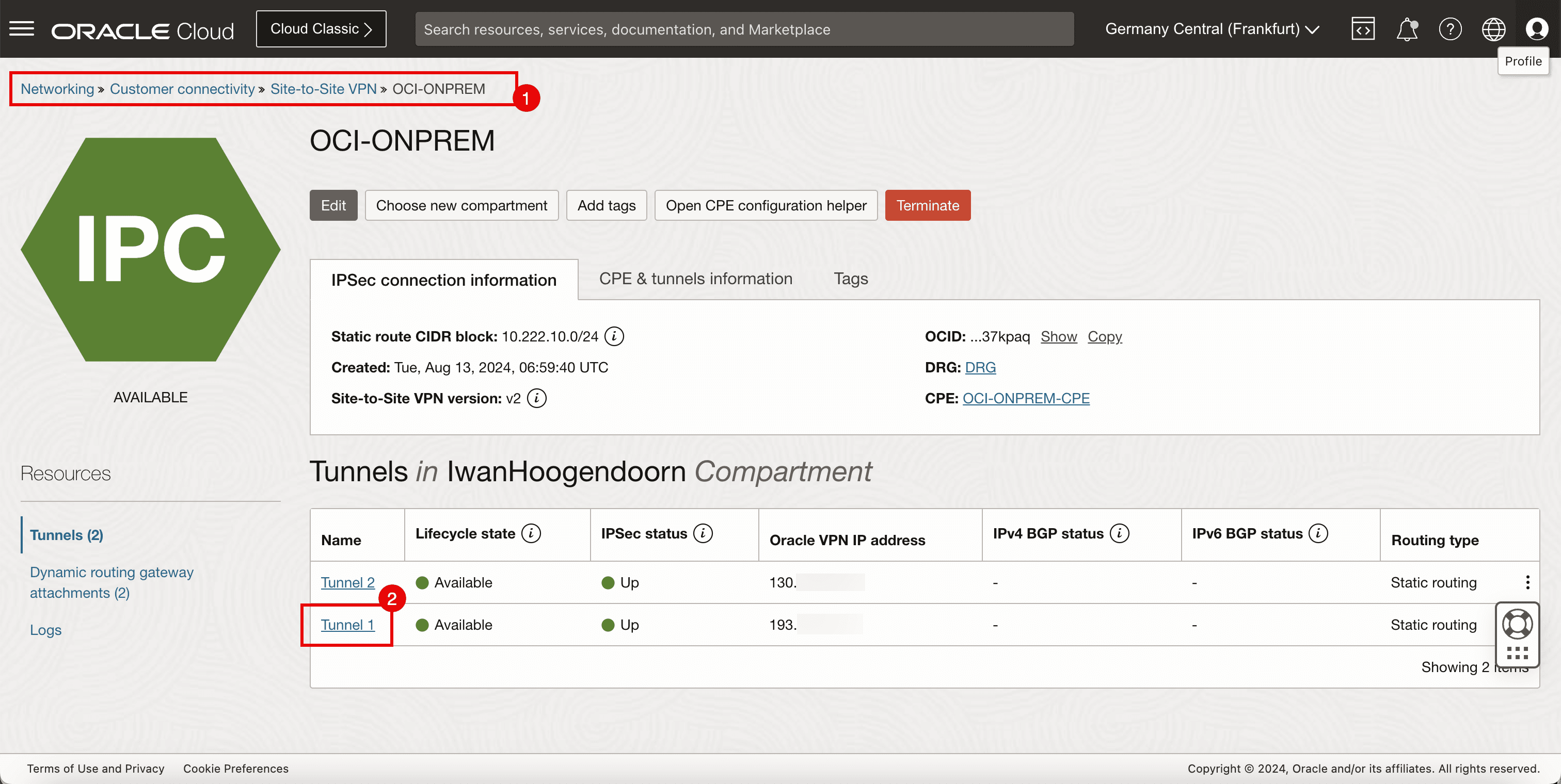
-
To get the shared secret, click show.
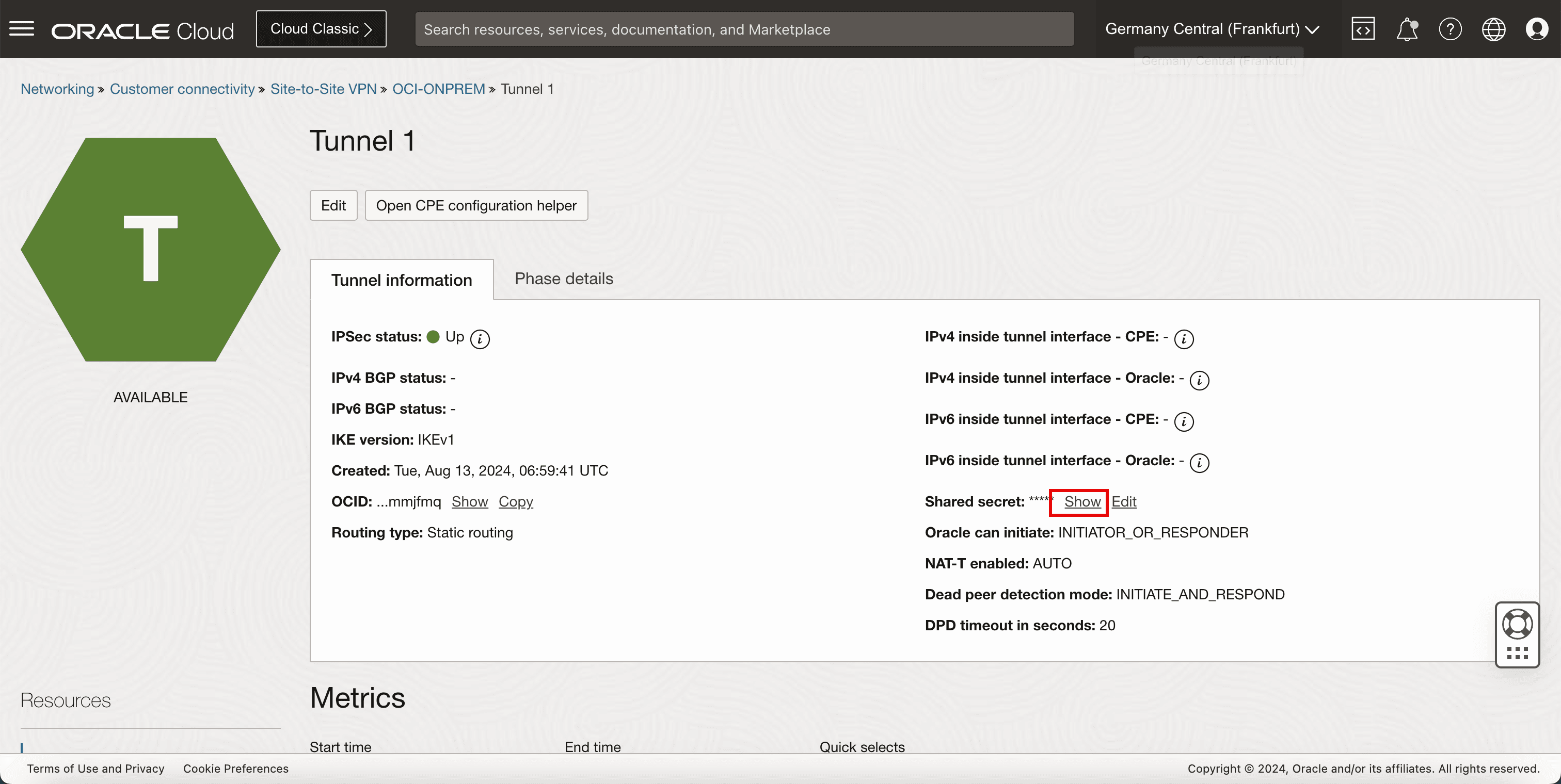
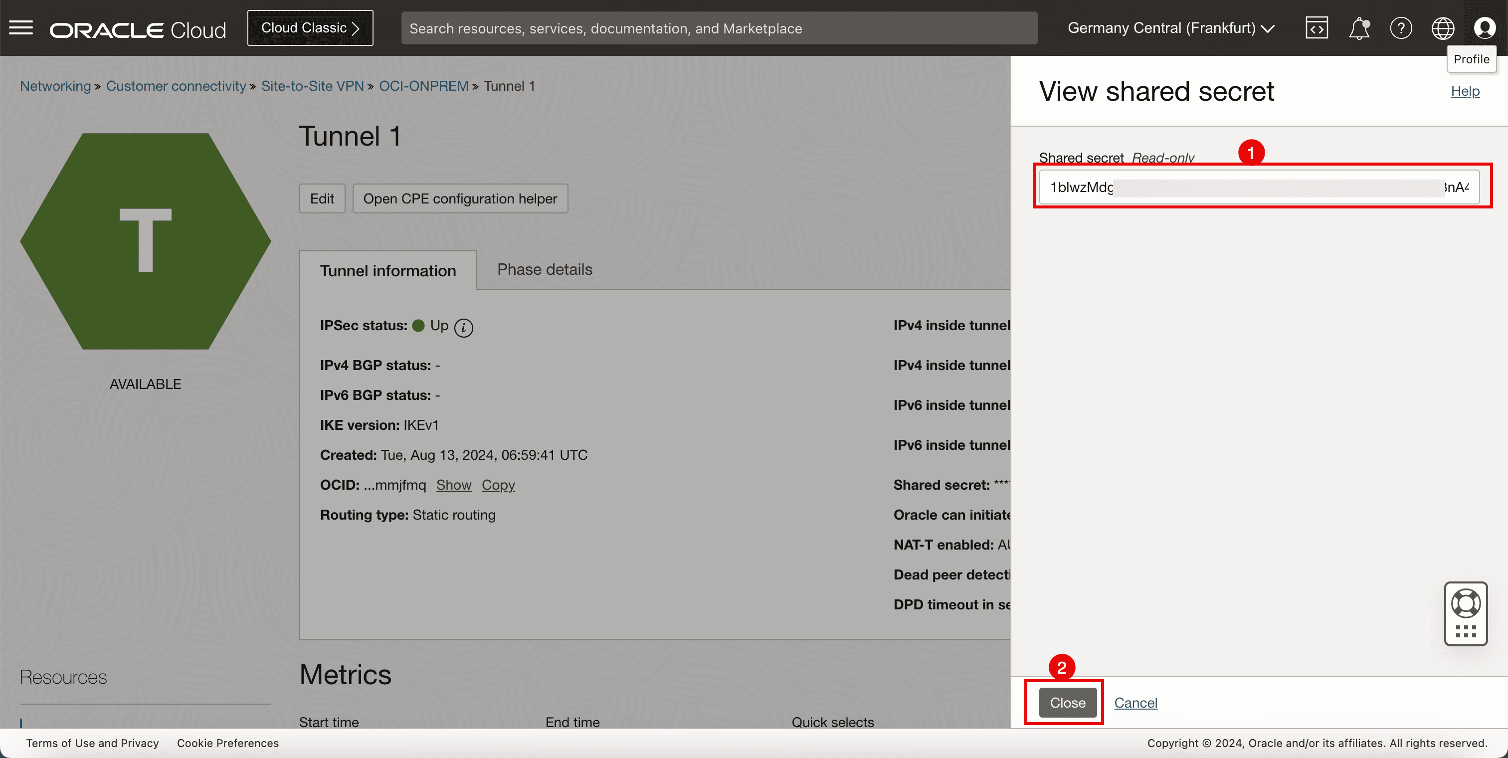
- Copy the shared secret for tunnel 1 and save it on a notepad to access it later.
- Click Close.
- Go to the OCI Console, navigate to Networking, Customer Connectivity, Site-to-Site VPN and click the configured VPN.
- Click the second tunnel configuration.
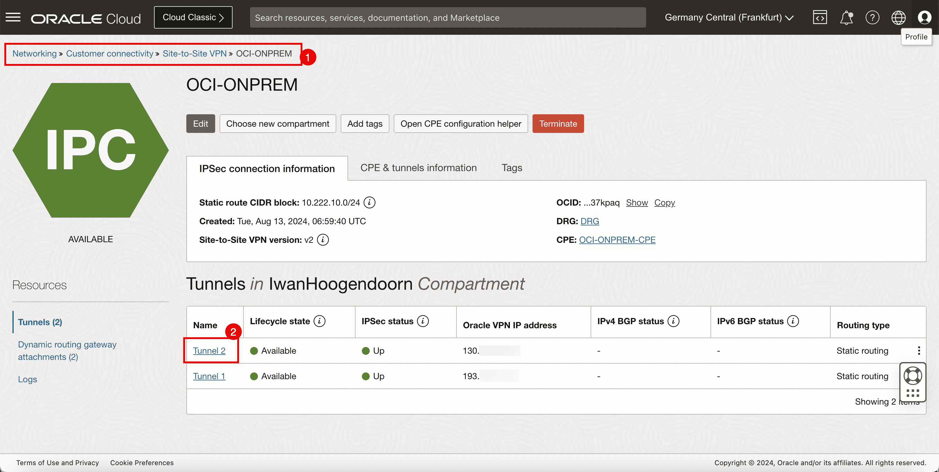
-
To get the shared secret, click show.
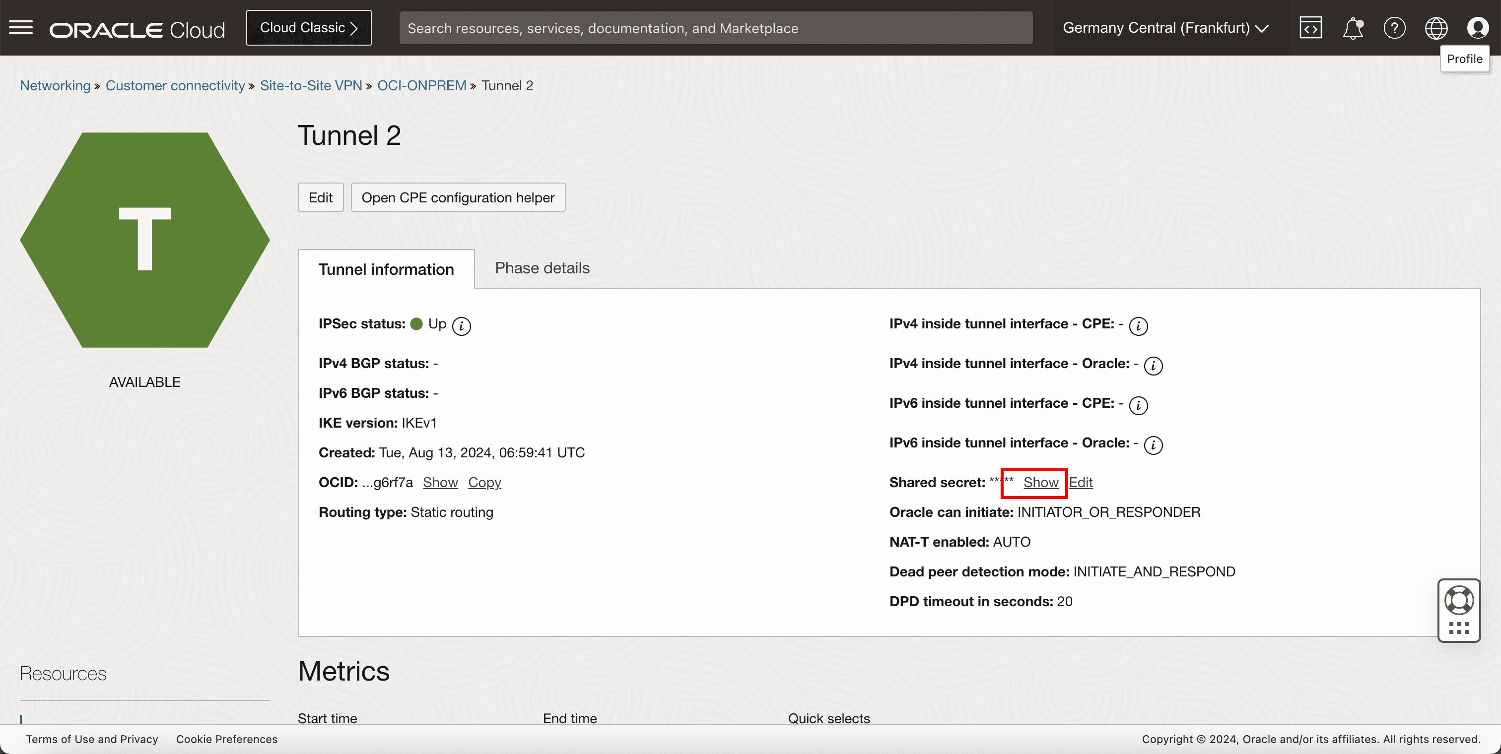
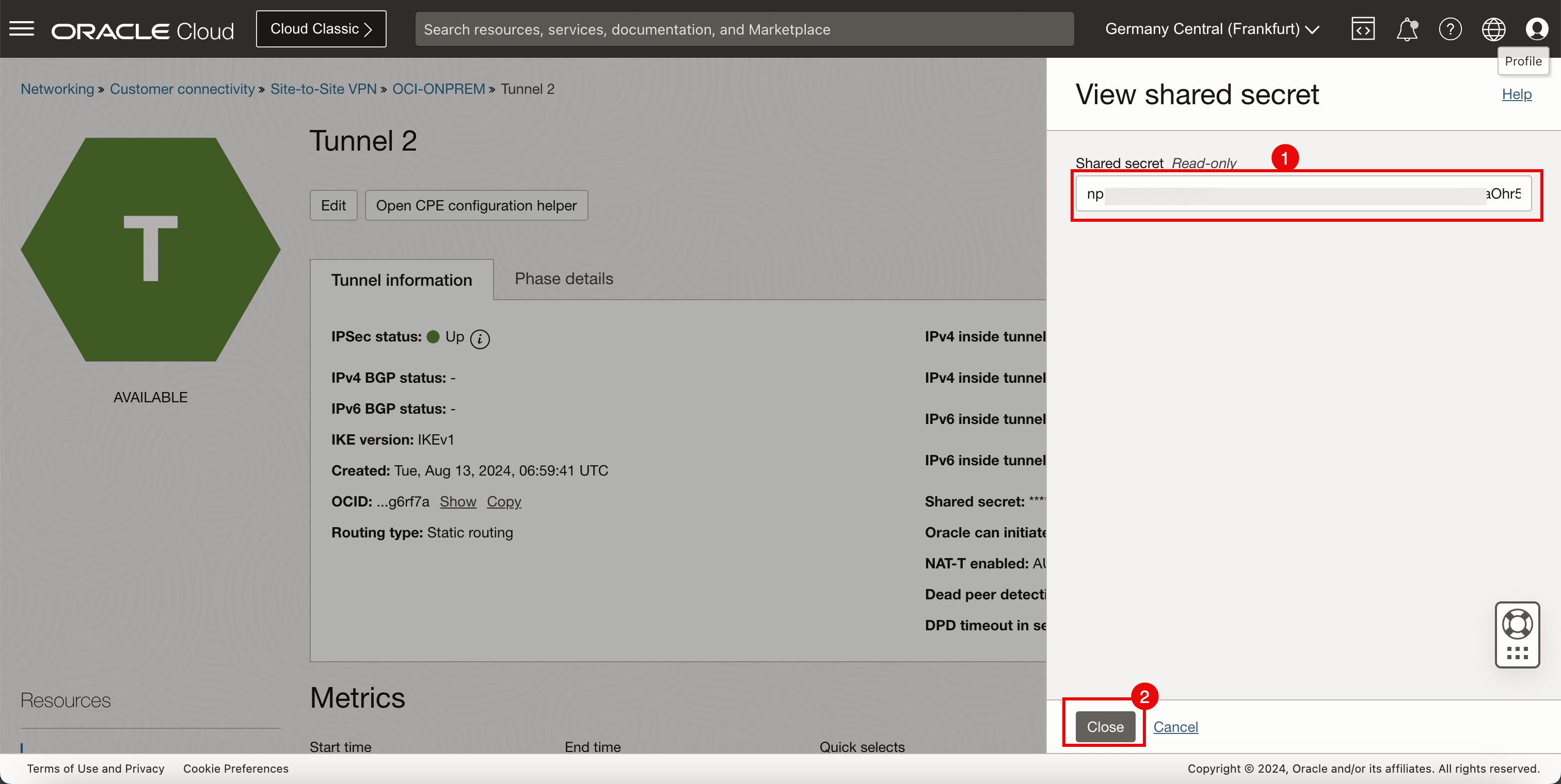
- Copy the shared secret for tunnel 2 and save it on a notepad to access it later.
- Click Close.
-
Configure the shared secrets on Libreswan. Create and edit the following file (
shared.secrets) to configure the shared secrets for both tunnels.[root@cpe ipsec.d]# nano /etc/ipsec.d/shared.secrets
-
Make sure the
/etc/ipsec.d/shared.secretsfile contains the following content.143.xxx.xxx.xxx 193.xxx.xxx.xxx : PSK "1blwzMdgQ5XXXoiQwF96tqc7c7" 143.xxx.xxx.xxx 130.xxx.xxx.xxx : PSK "npLt23Ym6E1XXXhr5egvYSuzKC"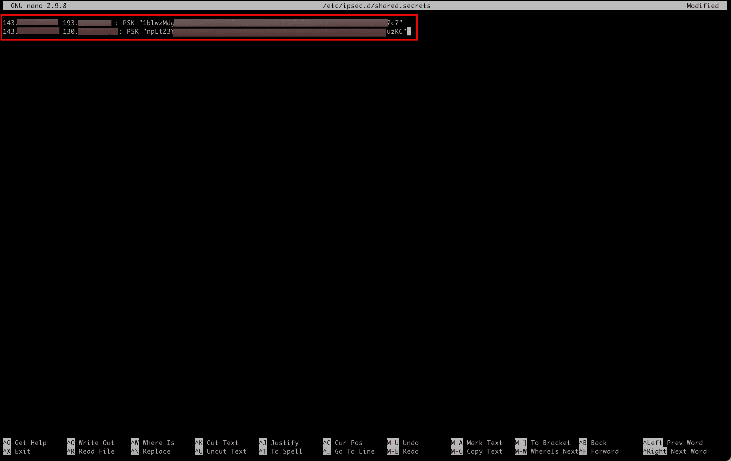
- Run the following command to verify the content of the file.
- Note that the output will be the same as the content of the file.
[root@cpe ipsec.d]# more /etc/ipsec.d/shared.secrets
-
Run the following command to start the IPSec service on Libreswan. This will not establish the tunnels yet.
[root@cpe ipsec.d]# ipsec start
-
Run the following command to verify the status of the IPSec connections.
[root@cpe ipsec.d]# ipsec verify -
Note that the verification looks ok, without any errors.

-
Task 8: Open the Firewall on the CPE Instance in the Source OCI Region and Configure the VCN and Subnet Security Lists
Configure the VCN and subnet security lists to allow the ingress ports required for the IPSec connection. To allow the tunnels to be established correctly, you need to make sure the network security on both sides is allowing the ports that are required.
-
Start with the source OCI region that hosts Libreswan as a CPE.
- Go to the OCI Console, navigate to Networking, Virtual cloud networks, select the VCN and click Security Lists.
- Select the Default Security List.
- Scroll down.

-
Make sure you have added the following ingress security rules.
Source IP Protocol Source Port Destination Port 0.0.0.0/0 UDP All 500 0.0.0.0/0 UDP All 4500 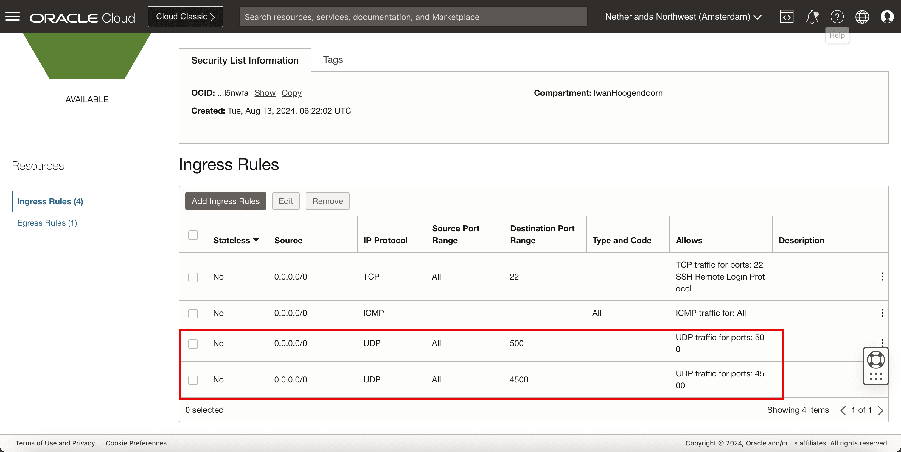
-
Open the firewall ports on the Libreswan CPE.
-
Run the following command to review the existing configured firewall rules.
[root@cpe ipsec.d]# sudo firewall-cmd --list-all -
Note that there are no rules configured related to the IPSec ports.
-
Run the following command to allow UDP port
500on the CPE.[root@cpe ipsec.d]# sudo firewall-cmd --add-port=500/udp -
Run the following command to allow UDP port
4500on the CPE.[root@cpe ipsec.d]# sudo firewall-cmd --add-port=4500/udp -
Run the following command to make the firewall rules permanent so they will remain after a reboot.
[root@cpe ipsec.d]# sudo firewall-cmd --runtime-to-permanent -
Run the following command to review the existing configured firewall rules.
[root@cpe ipsec.d]# sudo firewall-cmd --list-all -
Note that there are no rules configured related to the IPSec ports.

-
Run the following command to make sure the firewall service for Libreswan is running.
[root@cpe ipsec.d]# systemctl status firewalld -
Note that the firewall service is active and running.

-
-
Run the following command to restart the IPSec service.
[root@cpe ipsec.d]# service ipsec restart
Disable the Linux Firewall on the CPE
In some cases (for testing purposes) it might be better to completely disable the Linux Firewall of the CPE Instance where Libreswan is running on. This can be done with the following command:
[root@cpe ipsec.d]# systemctl disable --now firewalld
Run the following command to make sure the firewall service for Libreswan is NOT running.
[root@cpe ipsec.d]# systemctl status firewalld
Task 9: Activate and Verify if the IPSec Tunnel is up on Both Sides
-
Run the following command to verify the IPSec status for both tunnels.
[root@cpe ipsec.d]# ipsec status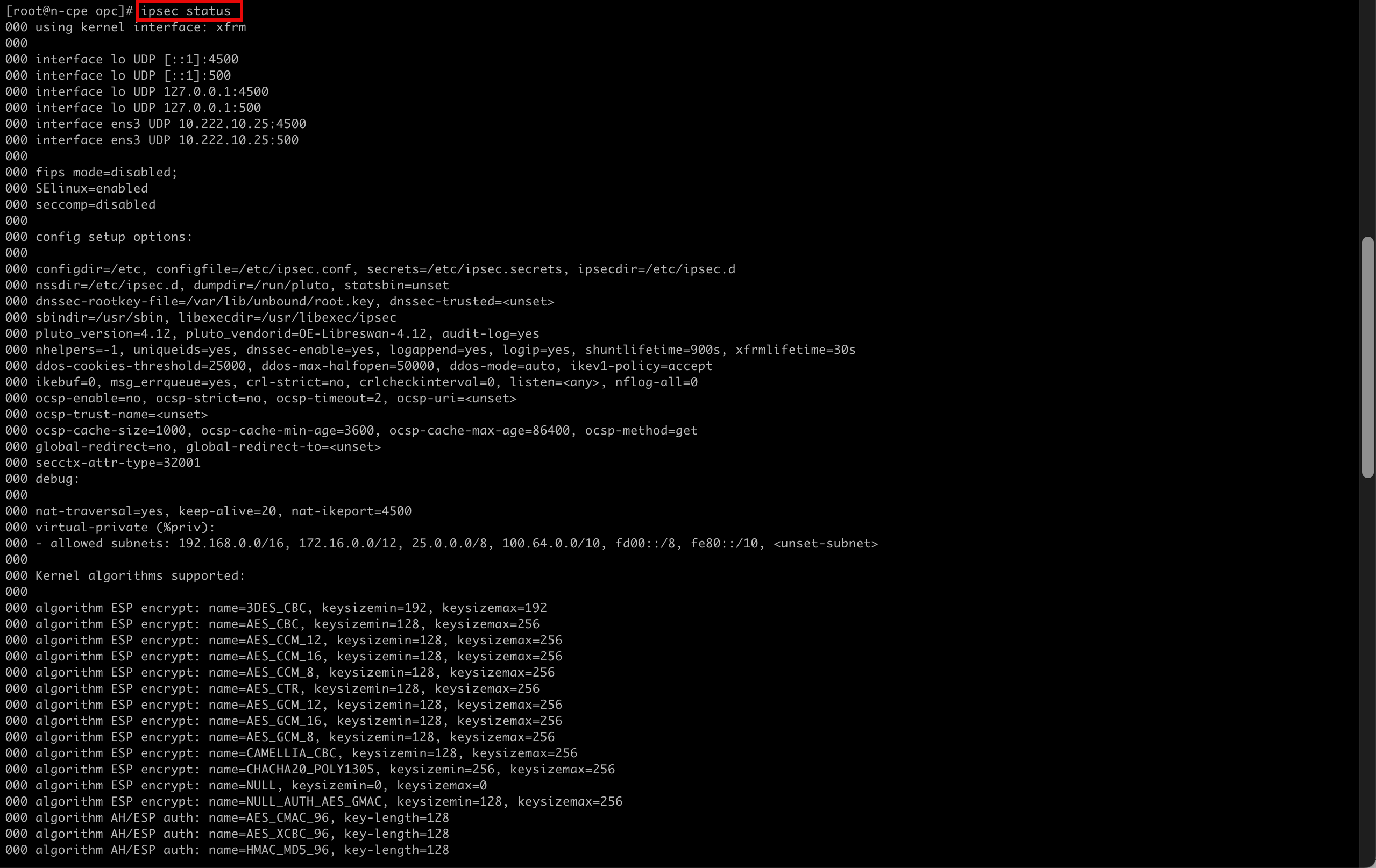
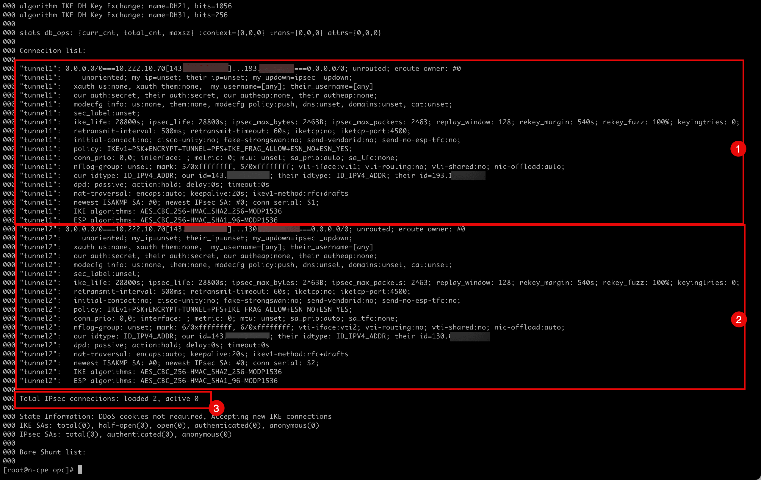
- Note the configuration and status for the first IPSec tunnel.
- Note the configuration and status for the second IPSec tunnel.
- Note the number of IPSec loaded is 2, and the active number is 0.
-
Run the following command to add
tunnel1.[root@cpe ipsec.d]# ipsec auto --add tunnel1 -
Note the output given by the terminal when
tunnel1is added.002 "tunnel1": terminating SAs using this connection 002 "tunnel1" #3: deleting state (STATE_QUICK_I2) aged 3.504567s and sending notification 005 "tunnel1" #3: ESP traffic information: in=0B out=0B 002 "tunnel1" #1: deleting state (STATE_MAIN_I4) aged 3.541172s and sending notification 002 "tunnel1": added IKEv1 connection -
Run the following command to bring
tunnel1up.[root@cpe ipsec.d]# ipsec auto --up tunnel1 -
Note the output given by the terminal when
tunnel1is brought up.002 "tunnel1" #5: initiating IKEv1 Main Mode connection 102 "tunnel1" #5: sent Main Mode request 104 "tunnel1" #5: sent Main Mode I2 106 "tunnel1" #5: sent Main Mode I3 002 "tunnel1" #5: Peer ID is ID_IPV4_ADDR: '193.122.0.91' 004 "tunnel1" #5: IKE SA established {auth=PRESHARED_KEY cipher=AES_CBC_256 integ=HMAC_SHA2_256 group=MODP1536} 002 "tunnel1" #6: initiating Quick Mode IKEv1+PSK+ENCRYPT+TUNNEL+PFS+UP+IKE_FRAG_ALLOW+ESN_NO+ESN_YES {using isakmp#5 msgid:b6364de1 proposal=AES_CBC_256-HMAC_SHA1_96-MODP1536 pfsgroup=MODP1536} 115 "tunnel1" #6: sent Quick Mode request 002 "tunnel1" #6: up-client output: vti interface "vti1" already exists with conflicting setting (perhaps need vti-sharing=yes ? 002 "tunnel1" #6: prepare-client output: vti interface "vti1" already exists with conflicting setting (perhaps need vti-sharing=yes ? 004 "tunnel1" #6: IPsec SA established tunnel mode {ESPinUDP=>0x5036cdcc <0x33c964f9 xfrm=AES_CBC_256-HMAC_SHA1_96 NATD=193.122.0.91:4500 DPD=passive} -
Run the following command to add
tunnel2.[root@cpe ipsec.d]# ipsec auto --add tunnel2 -
Note the output given by the terminal when
tunnel2is added.002 "tunnel2": terminating SAs using this connection 002 "tunnel2" #4: deleting state (STATE_QUICK_I2) aged 25.694856s and sending notification 005 "tunnel2" #4: ESP traffic information: in=0B out=0B 002 "tunnel2" #2: deleting state (STATE_MAIN_I4) aged 25.731704s and sending notification 002 "tunnel2": added IKEv1 connection -
Run the following command to bring
tunnel2up.[root@cpe ipsec.d]# ipsec auto --up tunnel2 -
Note the output given by the terminal when
tunnel2is brought up.002 "tunnel2" #7: initiating IKEv1 Main Mode connection 102 "tunnel2" #7: sent Main Mode request 104 "tunnel2" #7: sent Main Mode I2 106 "tunnel2" #7: sent Main Mode I3 002 "tunnel2" #7: Peer ID is ID_IPV4_ADDR: '130.61.66.255' 004 "tunnel2" #7: IKE SA established {auth=PRESHARED_KEY cipher=AES_CBC_256 integ=HMAC_SHA2_256 group=MODP1536} 002 "tunnel2" #8: initiating Quick Mode IKEv1+PSK+ENCRYPT+TUNNEL+PFS+UP+IKE_FRAG_ALLOW+ESN_NO+ESN_YES {using isakmp#7 msgid:aeb4eb18 proposal=AES_CBC_256-HMAC_SHA1_96-MODP1536 pfsgroup=MODP1536} 115 "tunnel2" #8: sent Quick Mode request 002 "tunnel2" #8: up-client output: vti interface "vti2" already exists with conflicting setting (perhaps need vti-sharing=yes ? 002 "tunnel2" #8: prepare-client output: vti interface "vti2" already exists with conflicting setting (perhaps need vti-sharing=yes ? 004 "tunnel2" #8: IPsec SA established tunnel mode {ESPinUDP=>0x8bef7076 <0xe27d84a0 xfrm=AES_CBC_256-HMAC_SHA1_96 NATD=130.61.66.255:4500 DPD=passive} [root@cpe ipsec.d]# -
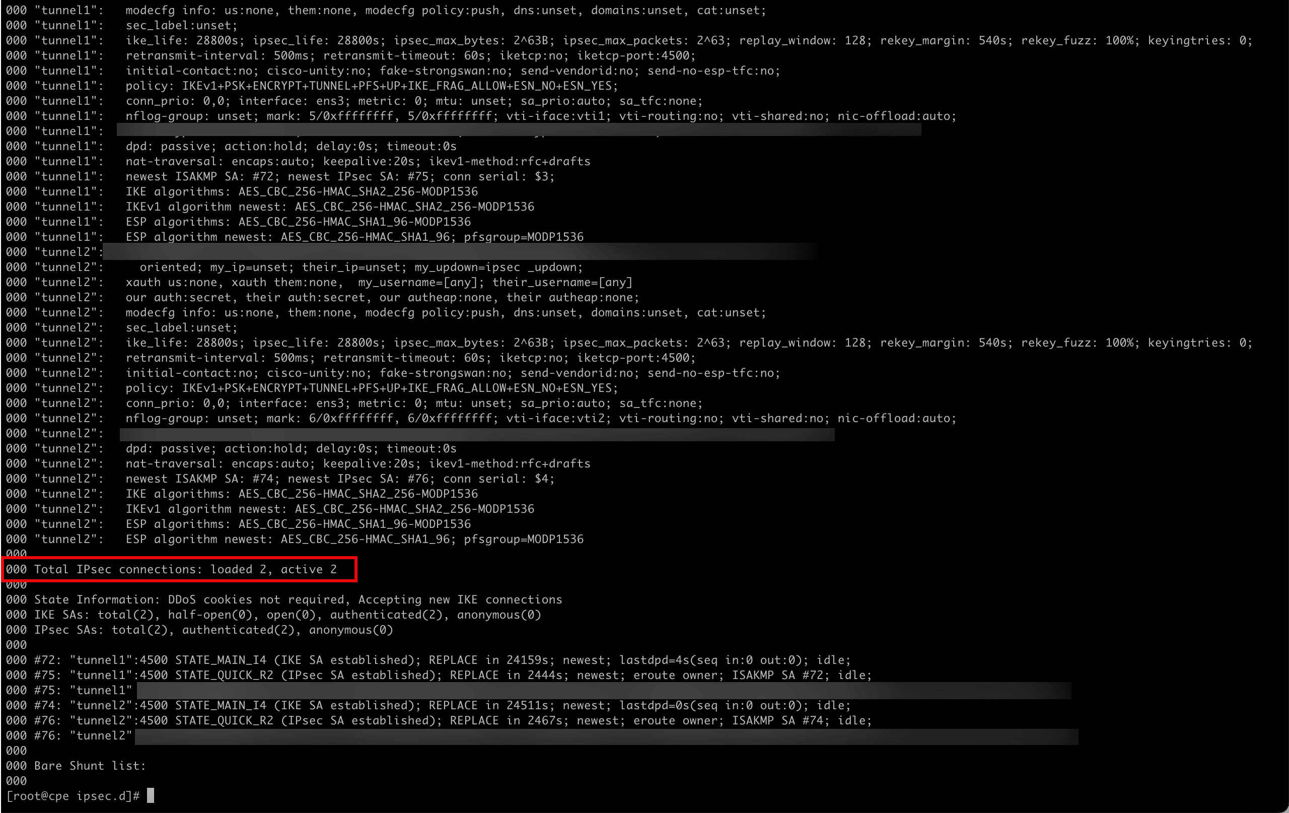
Run the following command to verify the IPSec status for both tunnels.
[root@cpe ipsec.d]# ipsec status -
Note that the active tunnels have gone from 0 to 2.
-
Go to the destination side on the OCI Console and check.
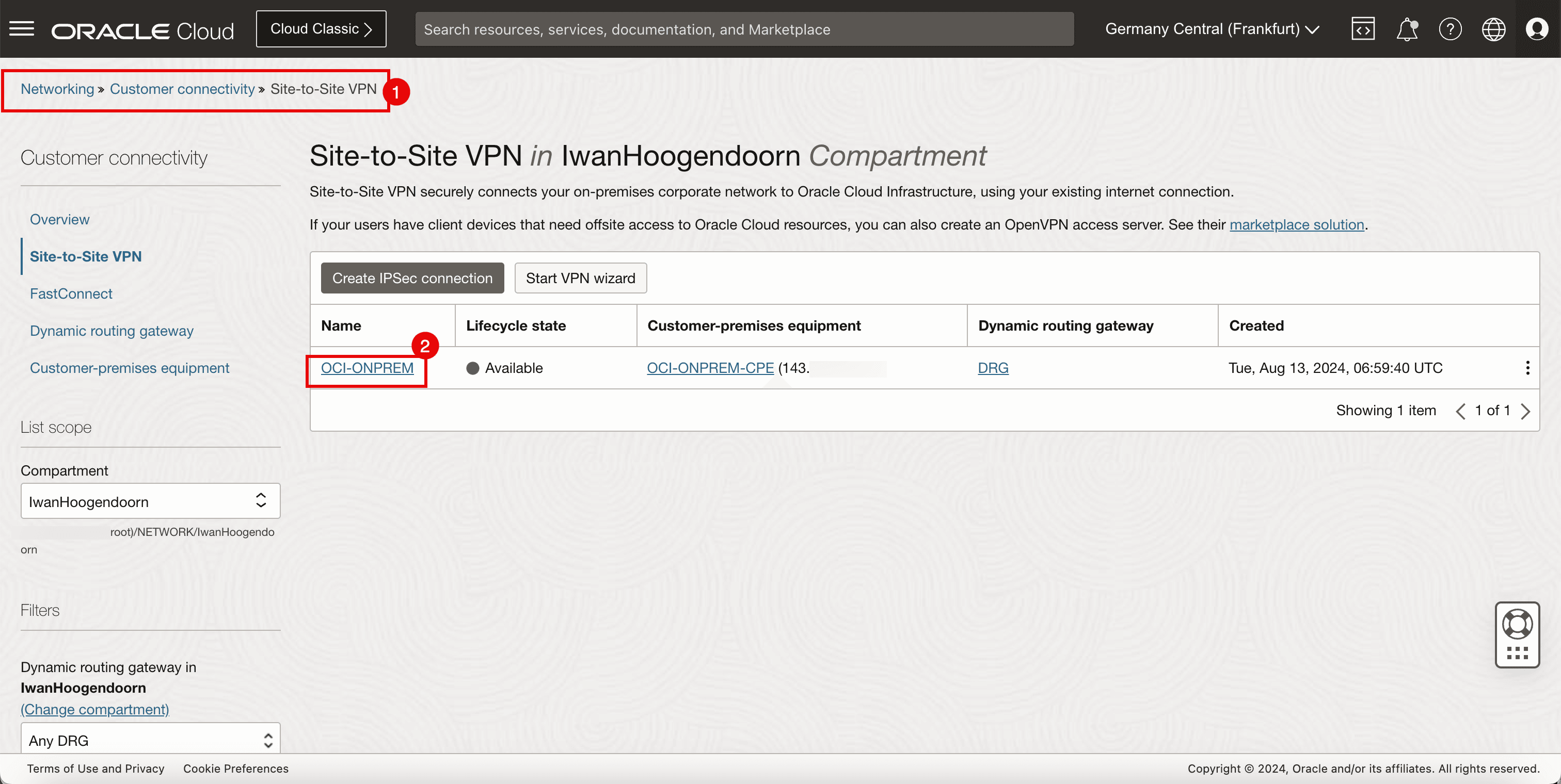
- Go to the OCI Console, navigate to Networking, Customer Connectivity and Site-to-Site VPN.
- Click the VPN connection.
-
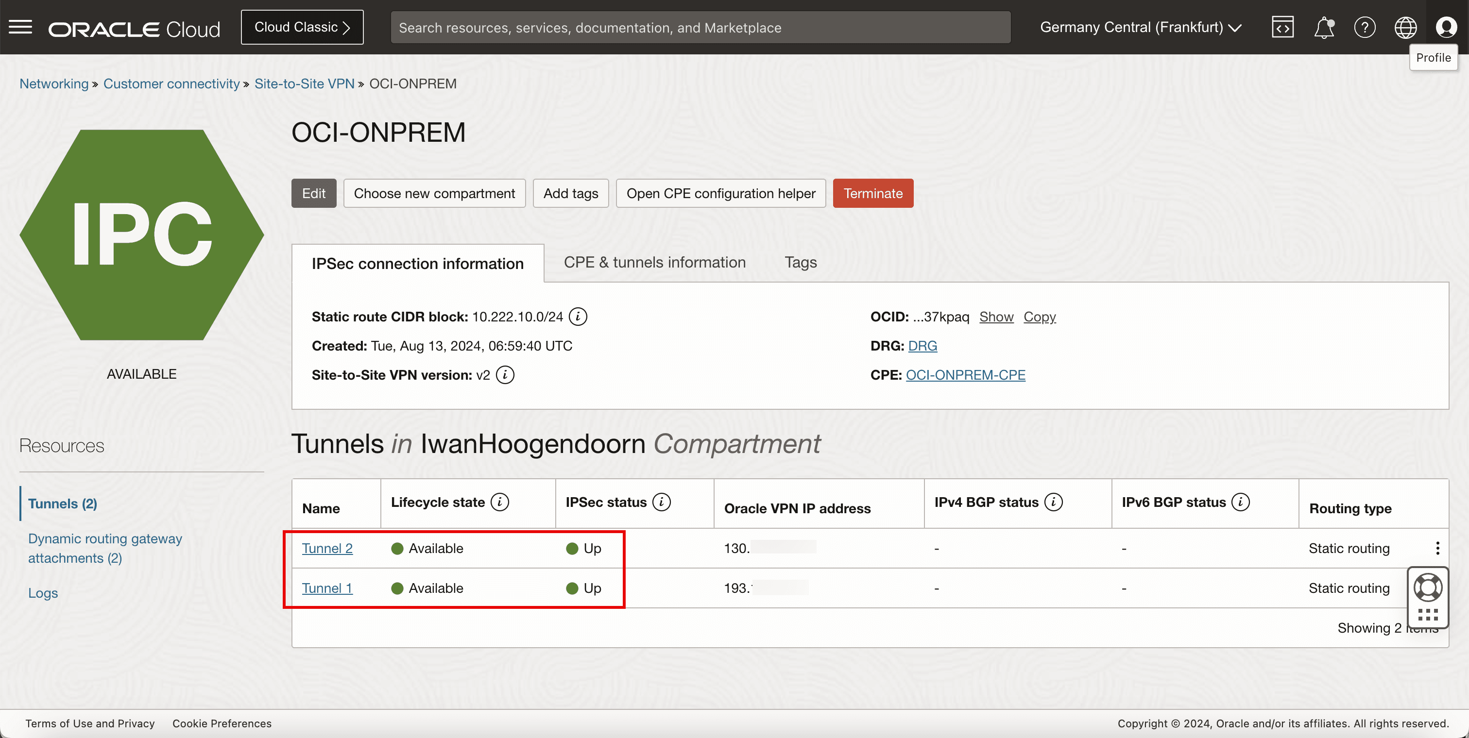
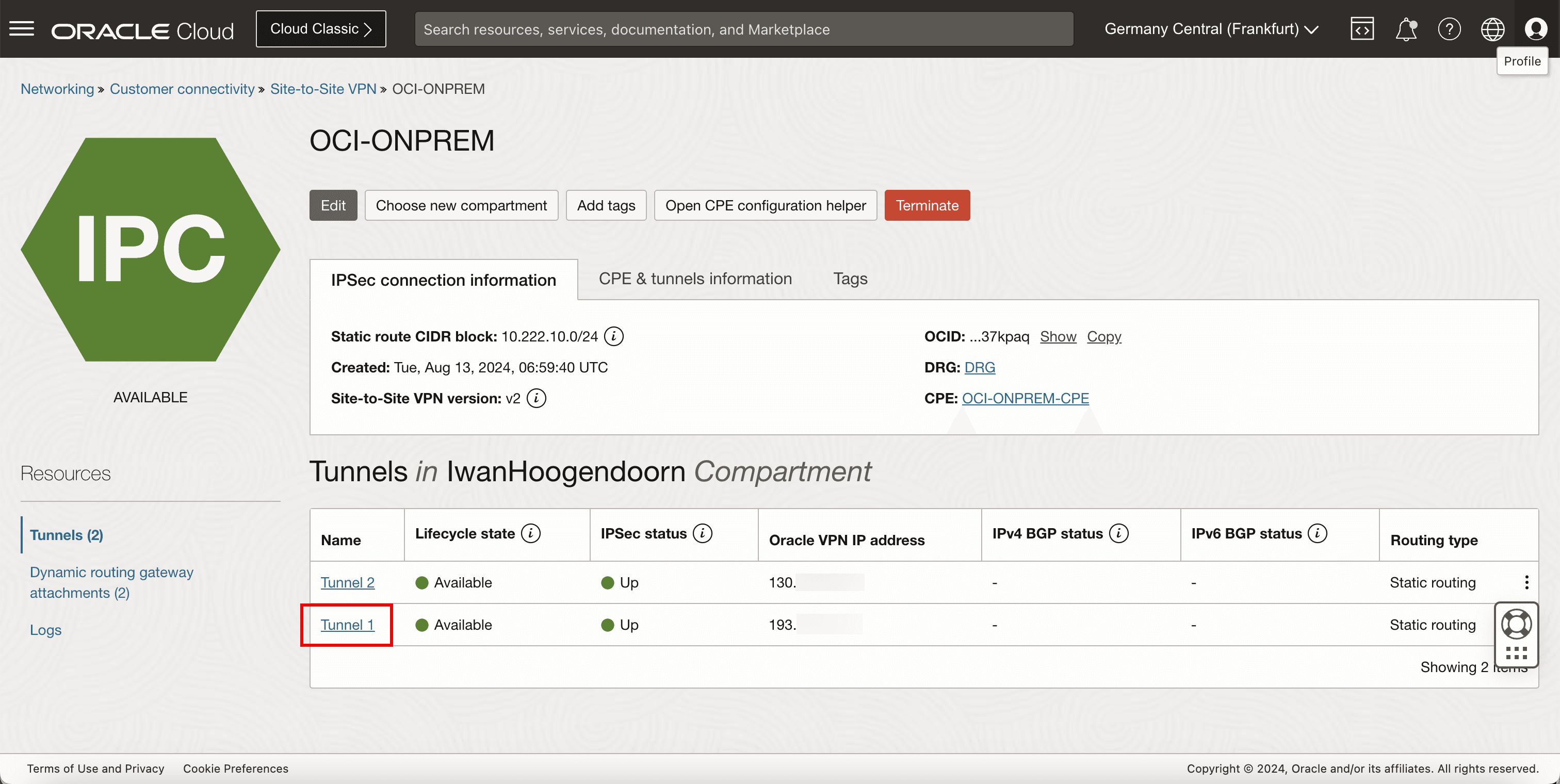
Note that Tunnel 1 and Tunnel 2 are both Available and Up.
-
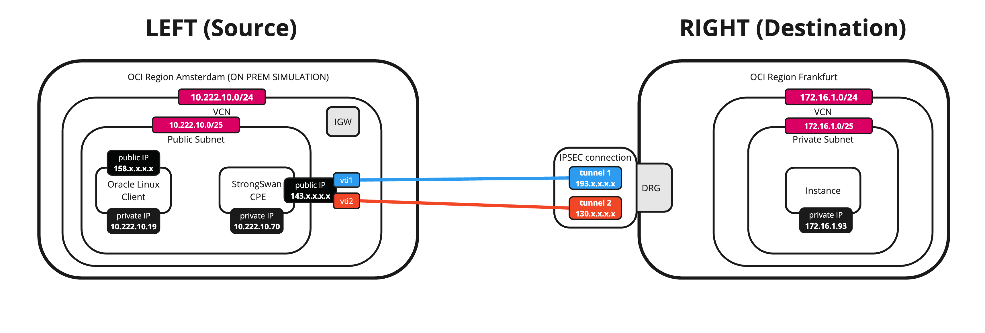
The following image illustrates what we have created so far.
Task 10: Configure the Static Routing
-
The tunnels are up, now we need to make sure the required traffic is routed through the tunnel.
-
Run the following command to review the configured tunnel interfaces.
[root@cpe ipsec.d]# ifconfig -
Note that vti1 is responsible for tunnel 1.
-
Note that vti2 is responsible for tunnel 2.

-
-
Run the following command to route
172.16.0.0/16network through the vti1 and vti2 interfaces.[root@cpe ipsec.d]# ip route add 172.16.0.0/16 nexthop dev vti1 weight 1 nexthop dev vti2 weight 1
-
Run the following command to review if the route is added.
[root@cpe ipsec.d]# ip route -
Note that the routes are added.

-
Task 11: Initiate Final Ping from the Source and Destination Instances
-
Initiate the final ping from source.
-
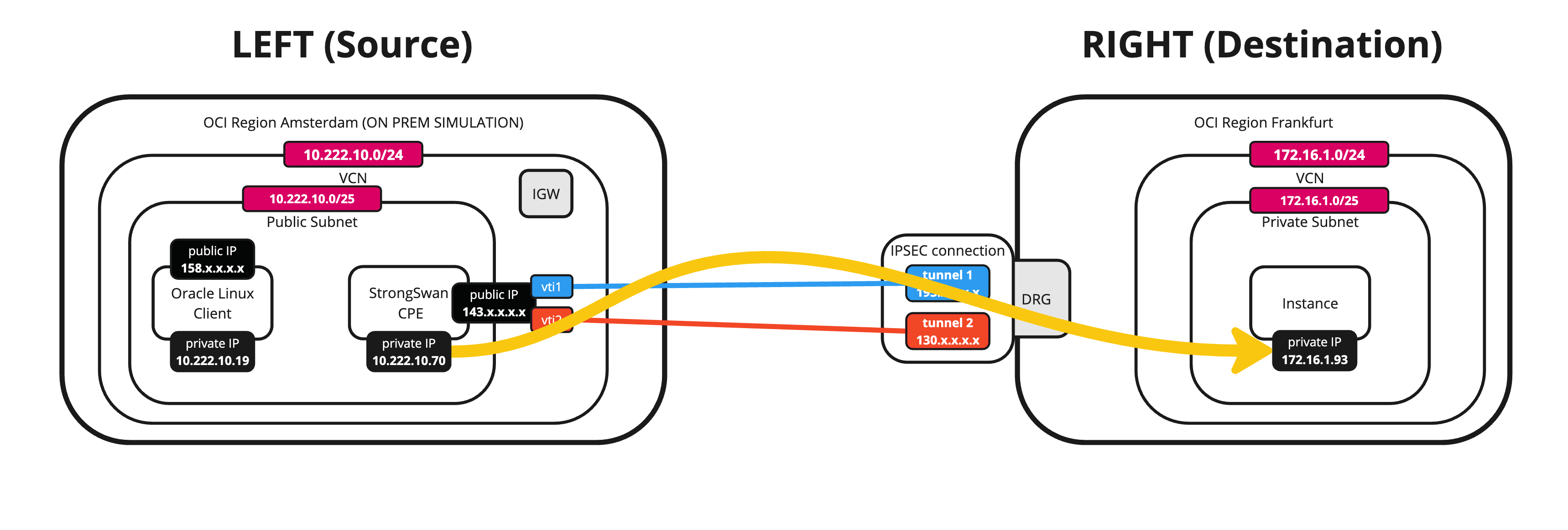
Run the following command from the source (CPE) to verify if the ping is working from the source OCI region to the destination OCI region.
[root@cpe ipsec.d]# ping 172.16.1.93 -c 4 -
Note that we have 0% packet loss.

-
-
The following image illustrates what we have created so far.
-
Initiate the final ping from destination.
-
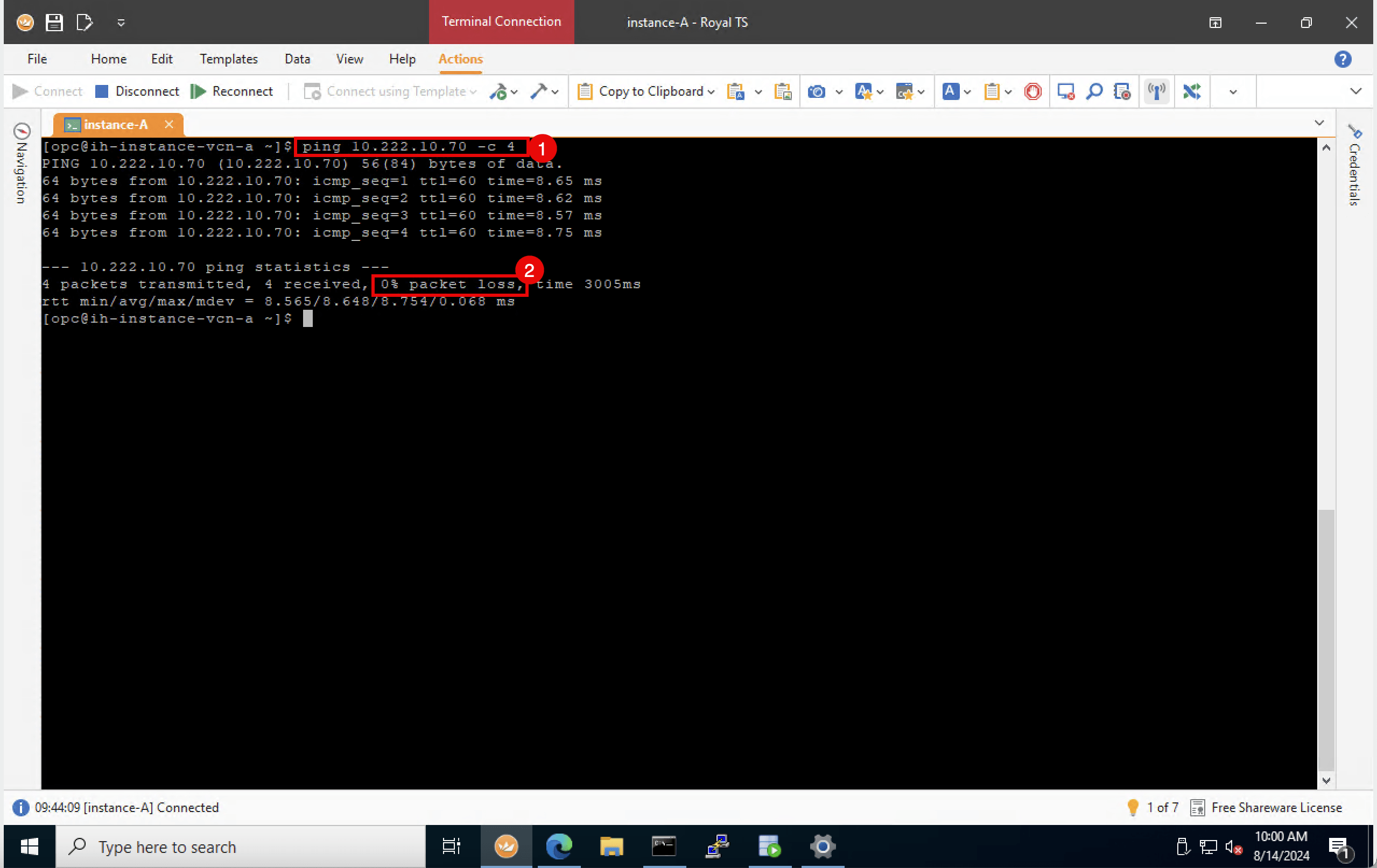
Run the following command from the destination to verify if the ping is working from the destination OCI region to the source OCI region (CPE).
[opc@ih-instance-vcn-a ~]$ ping 10.222.10.70 -c 4 -
Note that we have 0% packet loss.
-
-
The following image illustrates what we have created so far.
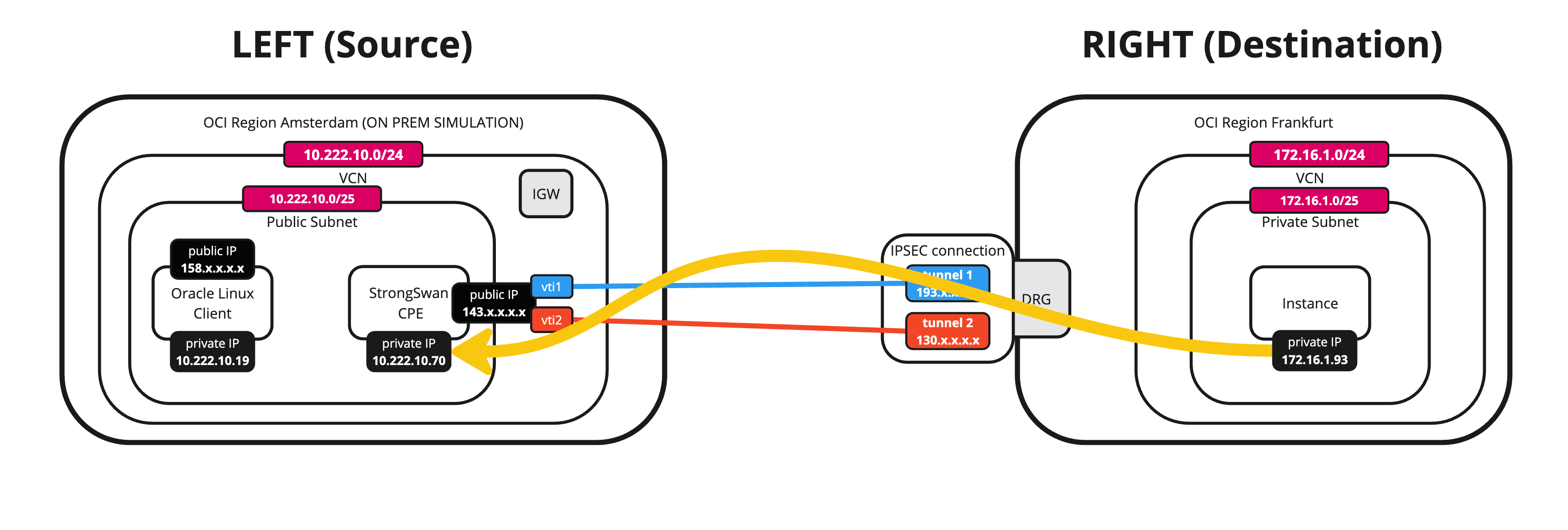
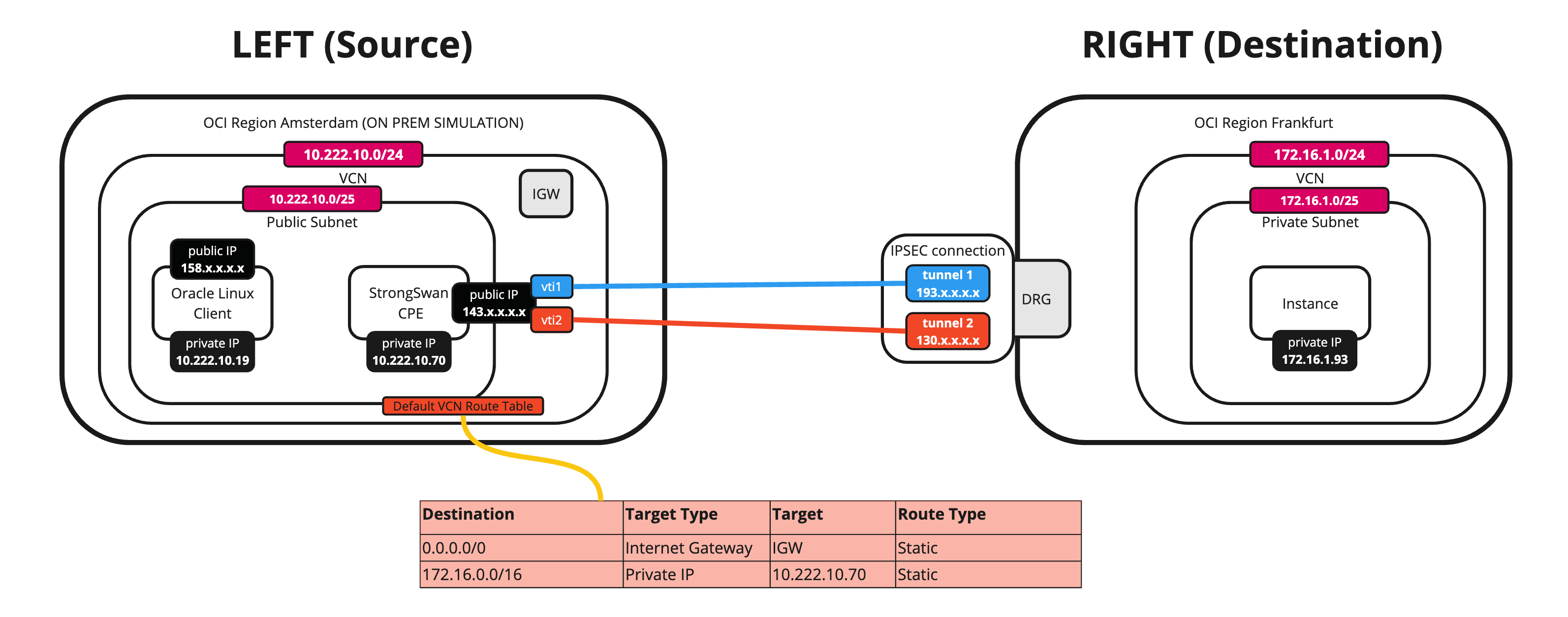
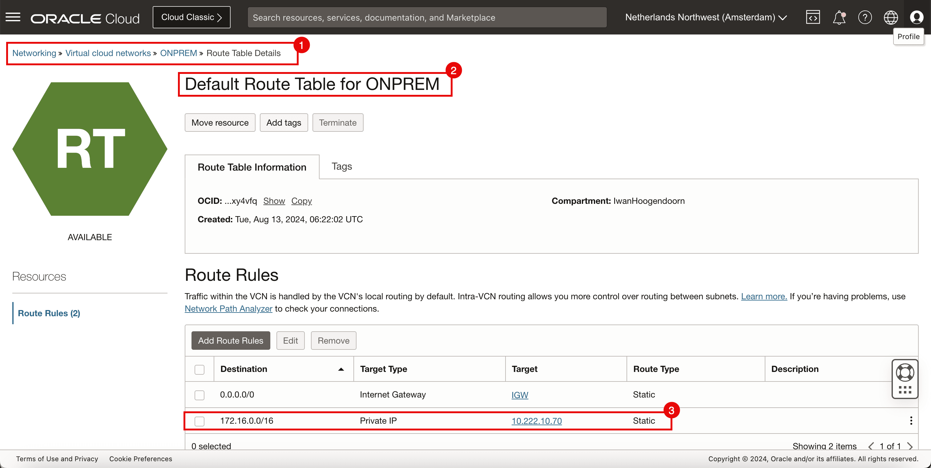
If you want to route all the traffic from the other instances in the same subnet on the source OCI region through the tunnels, you need to add a static route on the VCN route table. This route routes all traffic destined for
172.16.0.0/24to the CPE10.222.10.70. -
The following image illustrates what we have created so far with the full route table.
-
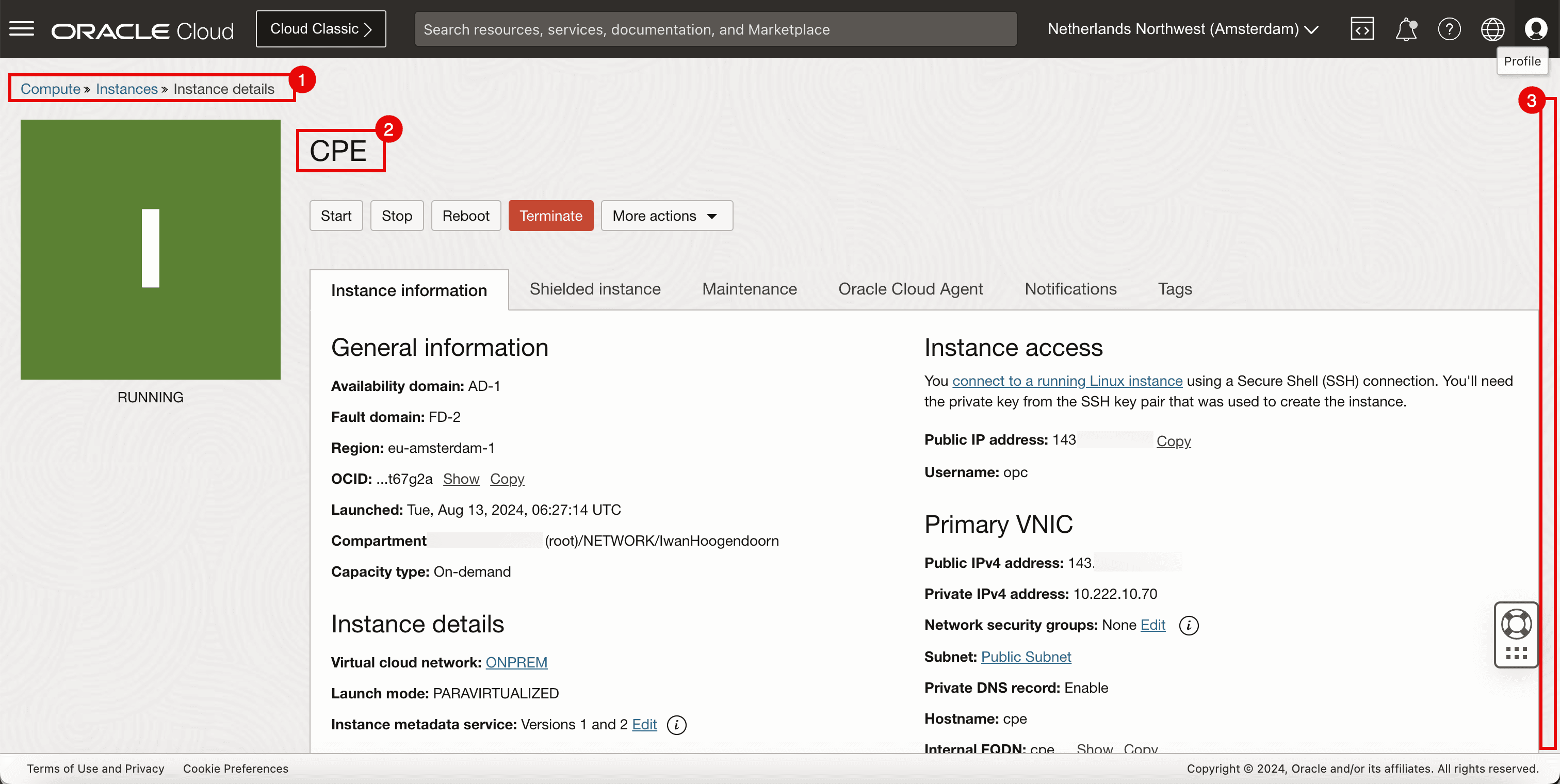
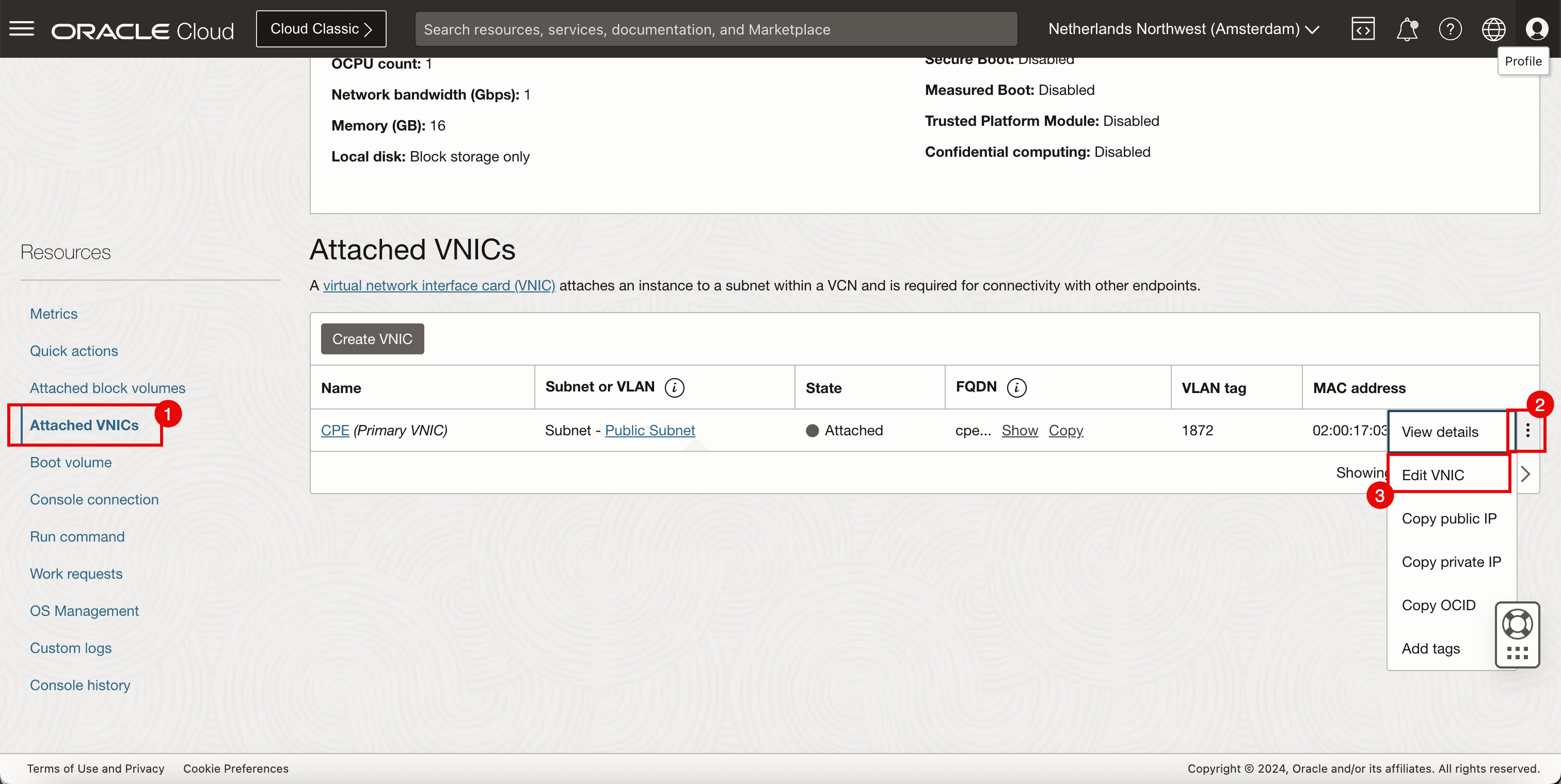
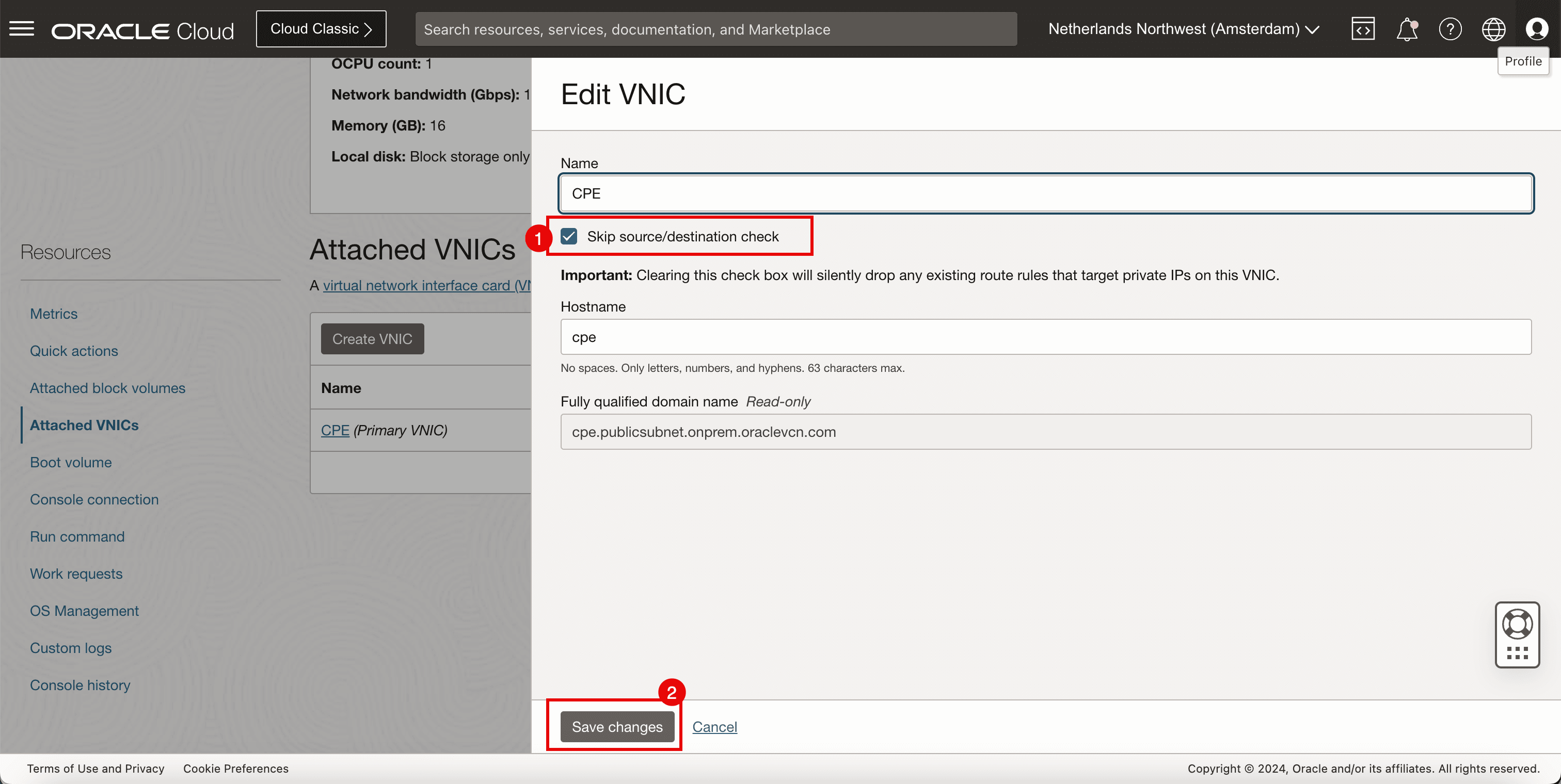
Before you can add a route towards a private IP address (Libreswan CPE) you first need to enable the Skip Source/Destination check on the instance (Libreswan CPE) vNIC.
- Navigate to Compute and Instances.
- Select CPE.
- Scroll down.
- Click Attached VNICs.
- Click the three dots.
- Click Edit VNIC.
- Select Skip source/destination check.
- Click Save changes.
-
Add the route.
- Go to Networking, Virtual cloud networks, select the VCN and click Route Tables.
- Select Default Route Table.
- Add a route rule for the Destination
172.16.0.0/16with the Target Type to be a Private IP and the Target to be10.222.10.70(Libreswan CPE).
-
Run the following command to verify the IP address of the CLIENT.
[opc@client ~]$ ip a -
Note that the CLIENT’s IP address is
10.222.10.19. -
Run the following command from the source (CLIENT) to verify if the ping is working from the source OCI region to the destination OCI region.
[opc@client ~]$ ping 172.16.1.93 -c 4 -
Note that we have 0% packet loss.

-
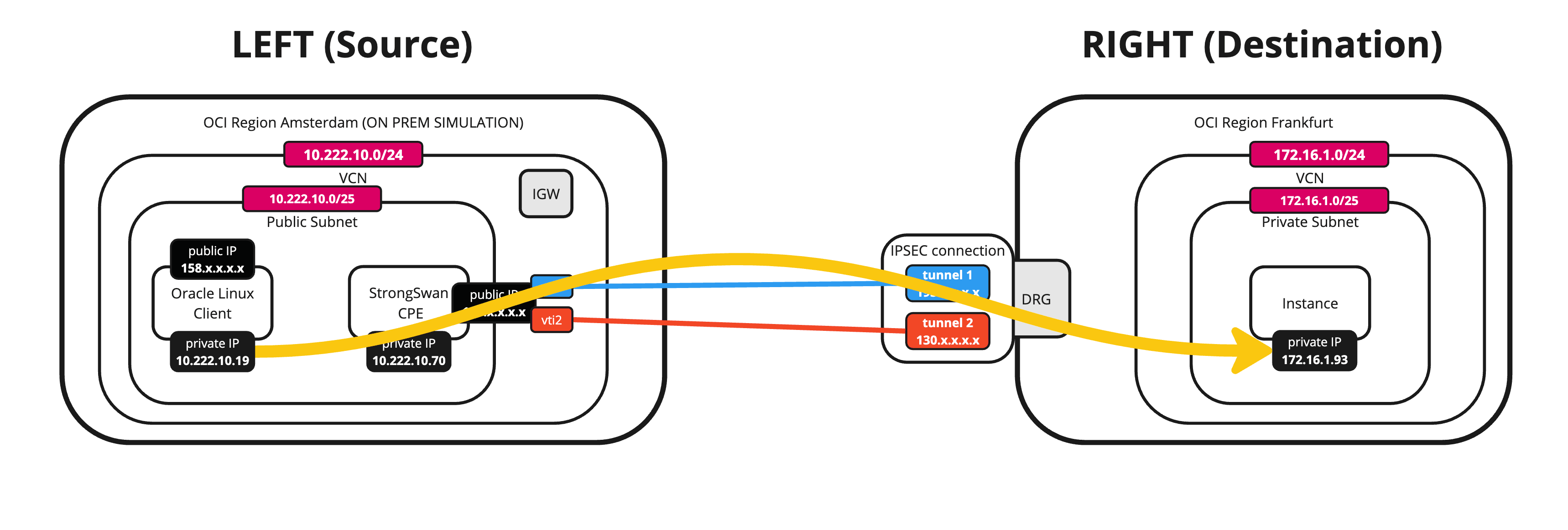
The following image illustrates what we have created so far.
-
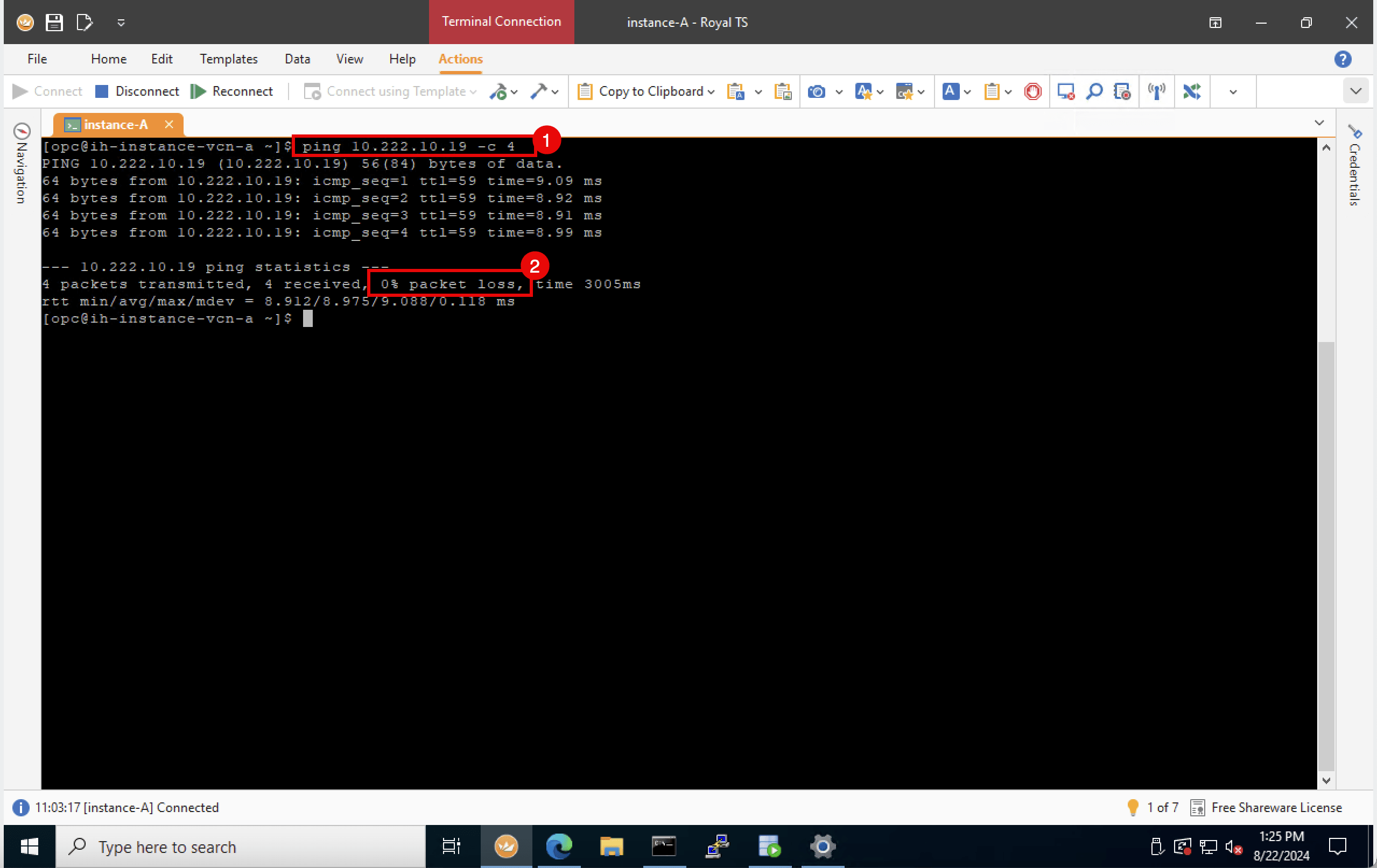
Run the following command from the destination to verify if the ping is working from the destination OCI region to the source OCI region (CLIENT).
[opc@ih-instance-vcn-a ~]$ ping 10.222.10.19 -c 4 -
Note that we have 0% packet loss.
-
-
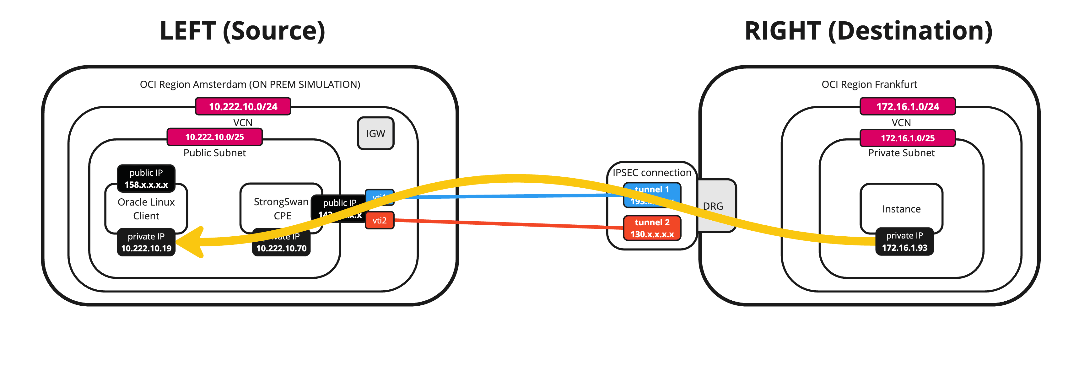
The following image illustrates what we have created so far.
Task 12: Verify the OCI Site-to-Site VPN Status
-
The VPN tunnels are up and traffic is flowing through then we can look at the dashboards in OCI on a per-tunnel basis.
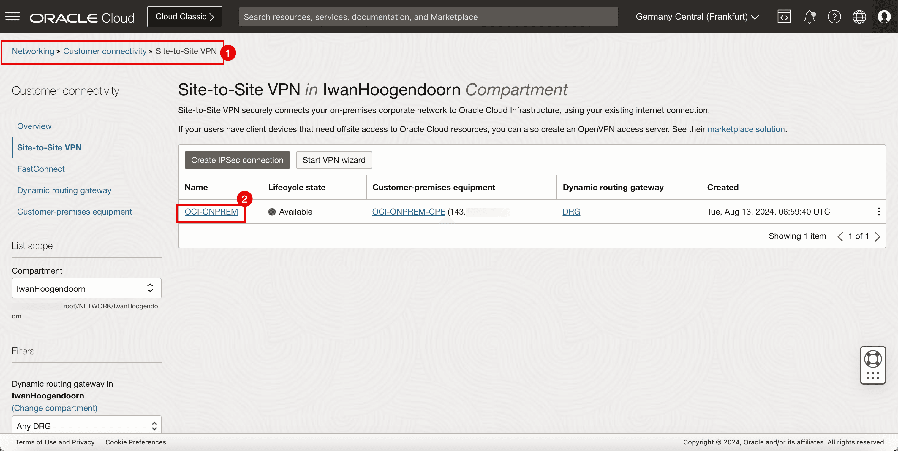
- Go to the OCI Console, Networking, Customer Connectivity and click Site-to-Site VPN.
- Click the VPN connection.
-
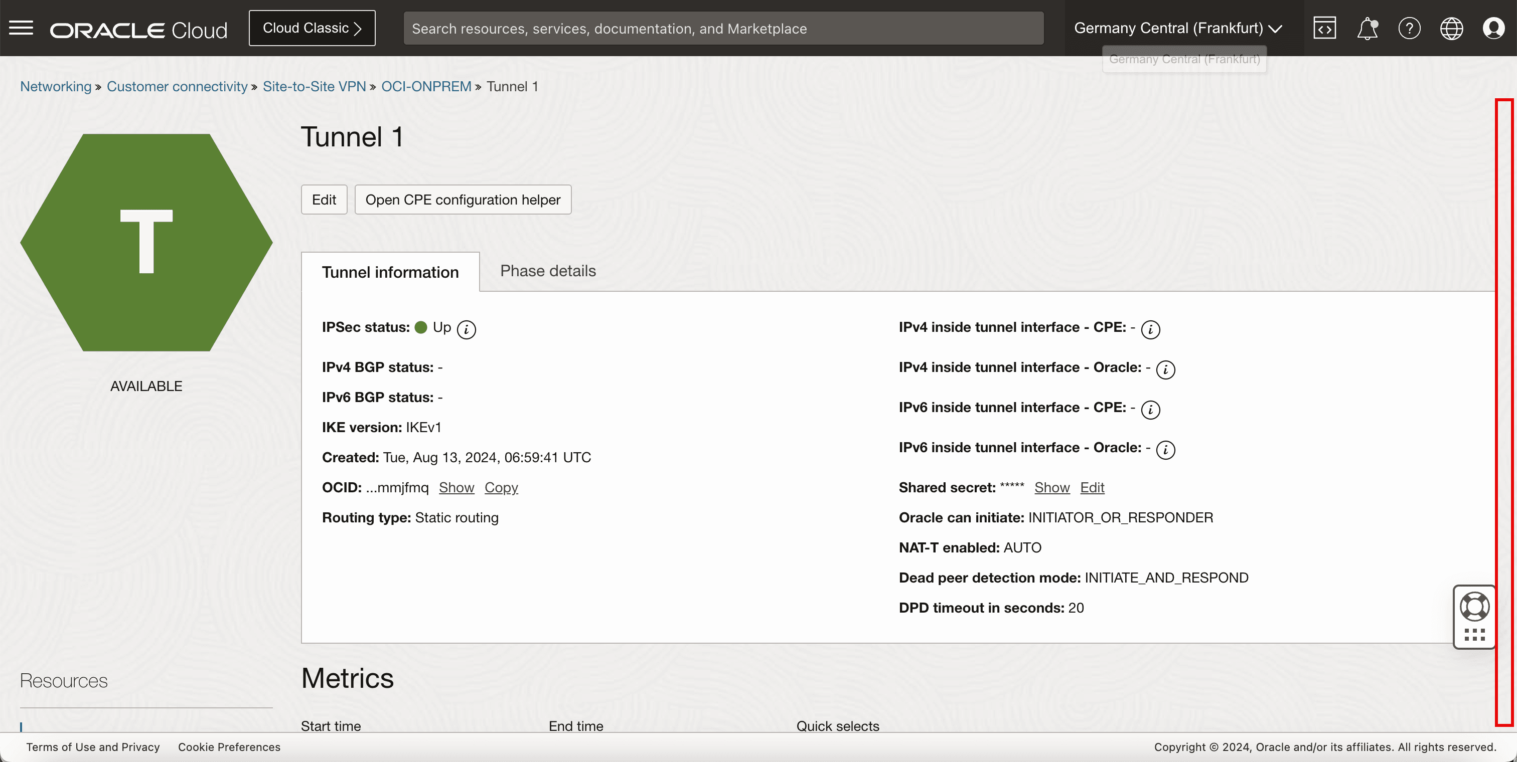
Click the first tunnel configuration.
-
Scroll down.
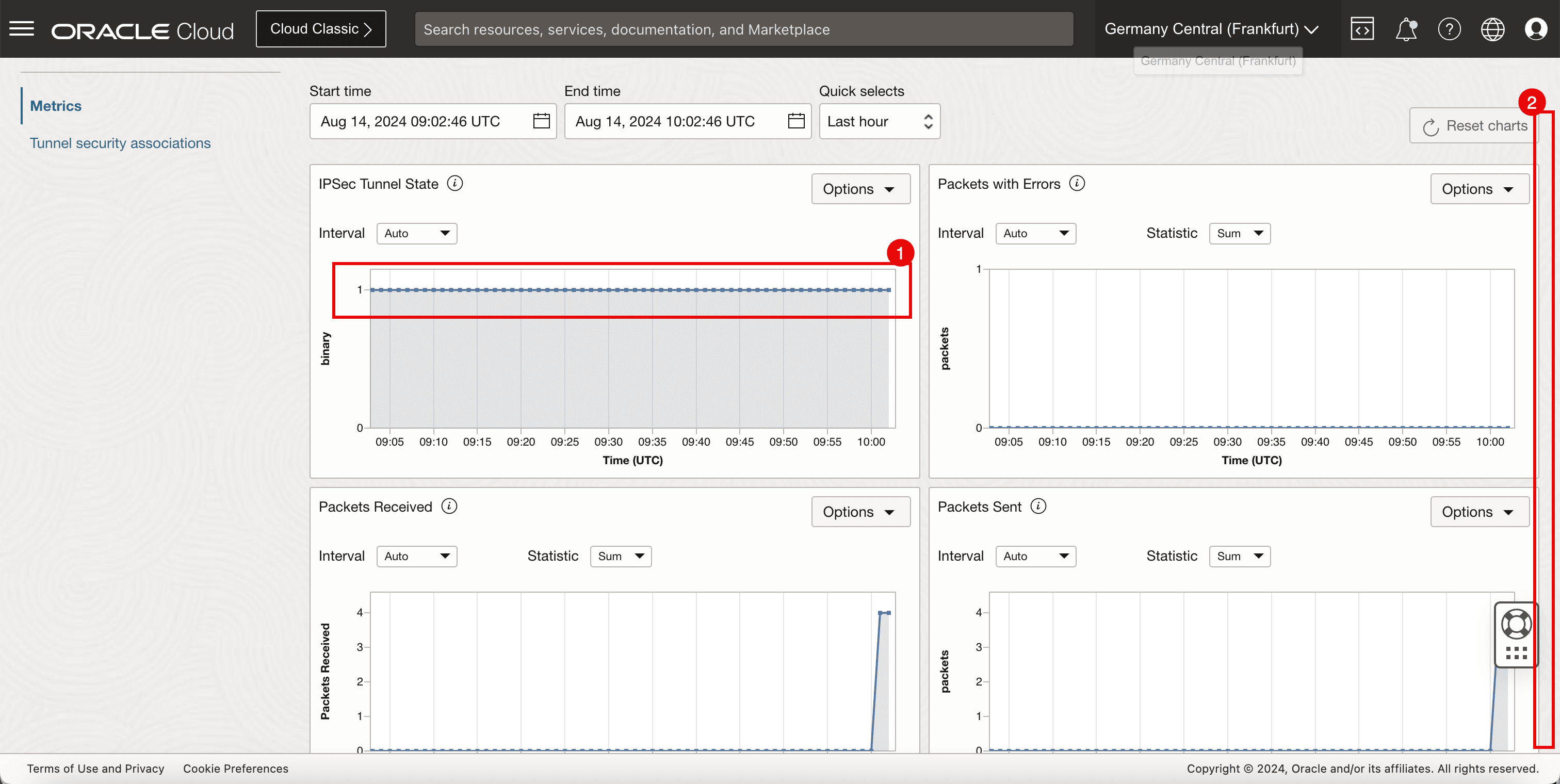
- Note that the IPSec tunnel state graph is constantly on 1, indicating the tunnel is up.
- Scroll down.
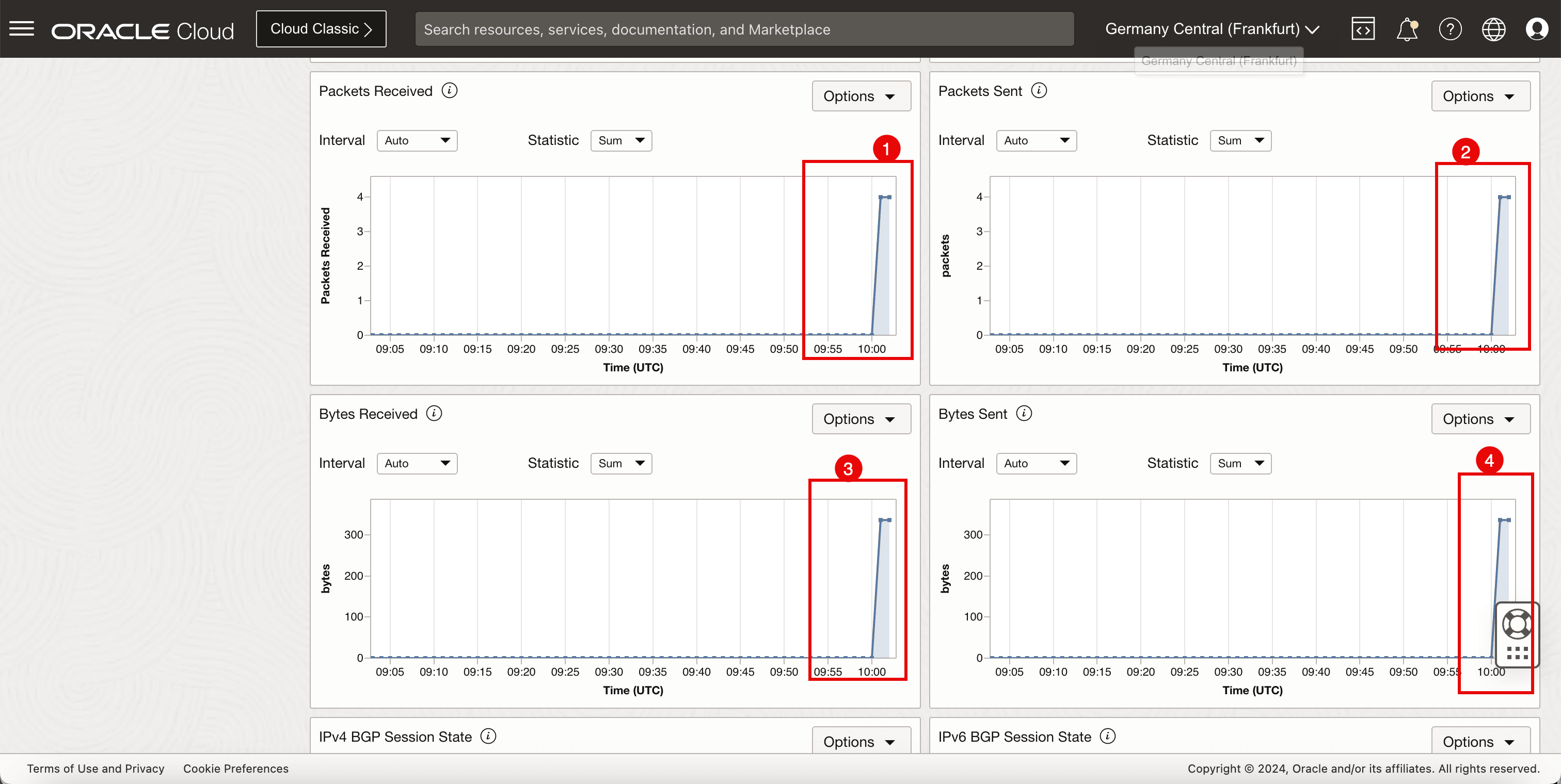
- Note that the packets received on this tunnel is 4, which corresponds with the number of ping packets sent from the source.
- Note that the packets sent on this tunnel is 4, which corresponds with the number of ping packets sent from the destination.
- Note the number of bytes received from the source.
- Note the number of bytes sent from the destination.
Task 13: Enable Equal Cost Multi-Path (ECMP) Routing
-
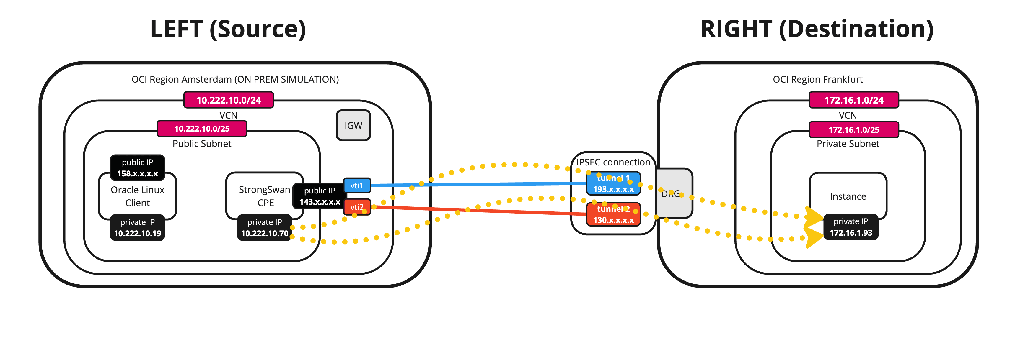
By default, the traffic is always sent using one tunnel interface (vti). If we want to use both tunnels for traffic forwarding we need to enable the ECMP routing on both sides.
On the Libreswan CPE, run the following command.
[root@cpe ipsec.d]# sysctl -w net.ipv4.fib_multipath_hash_policy=1 -
The following image illustrates what we have created so far.
-
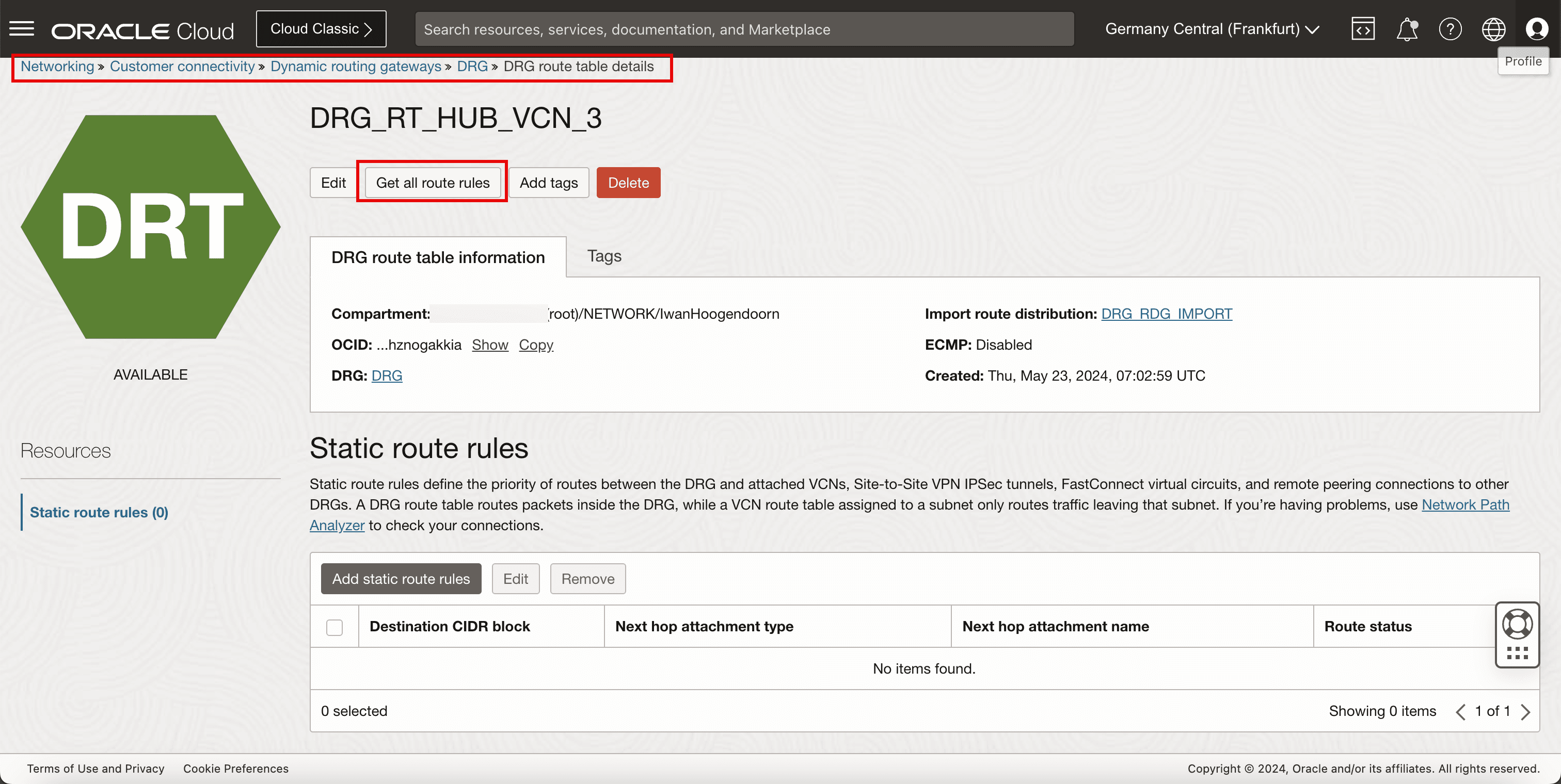
From the destination OCI region, go to the OCI Console, navigate to Networking, Customer Connectivity, Dynamic routing gateway, select the DRG, DRG route table details and select the DRG route table that is responsible for the routing.
-
Click Get all route rules.
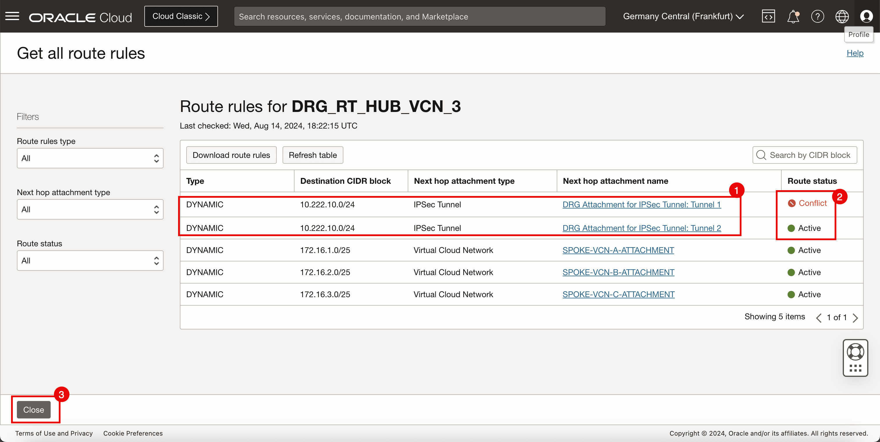
- Note that there are two routes available for the
10.222.10.0/24network. - Note that one route rule for the
10.222.10.0/24is marked as Conflict and the other marked as Active. - Click Close.
- Note that there are two routes available for the
-
Click Edit.
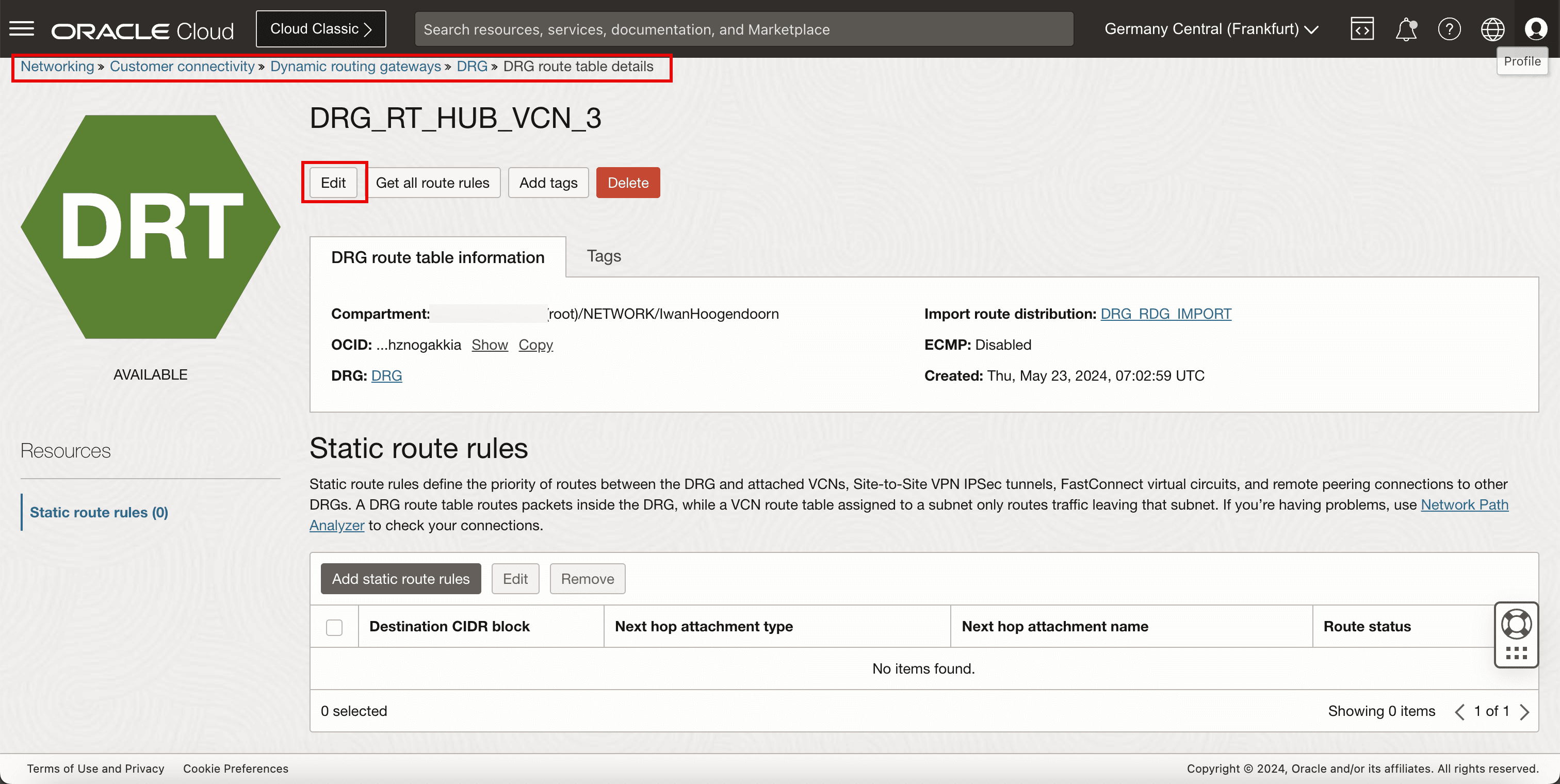
- Select Enable ECMP.
- Click Save changes.
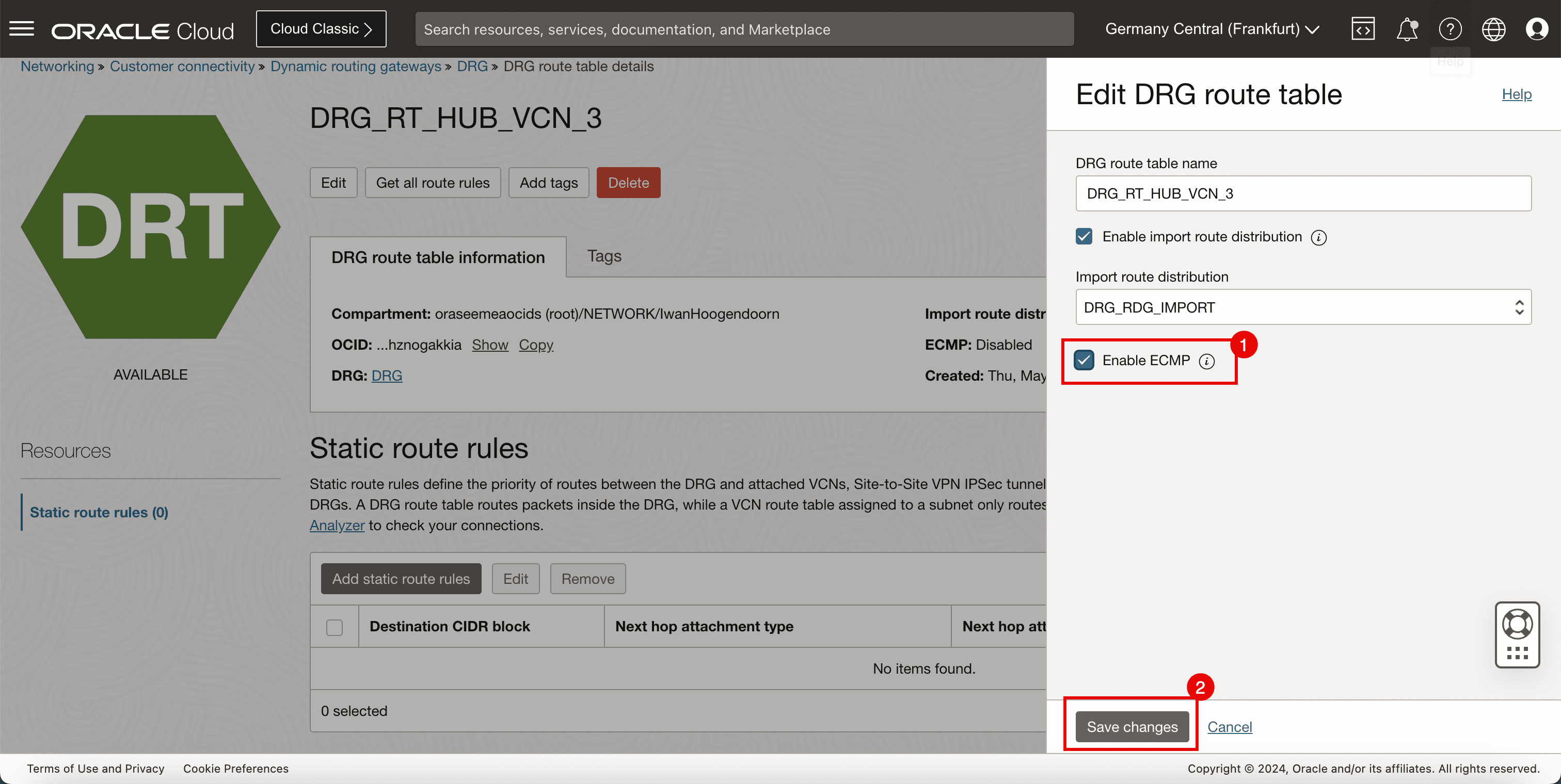
-
Click Get all route rules.

-
Note that both route rules for the
10.222.10.0/24are now marked as Active.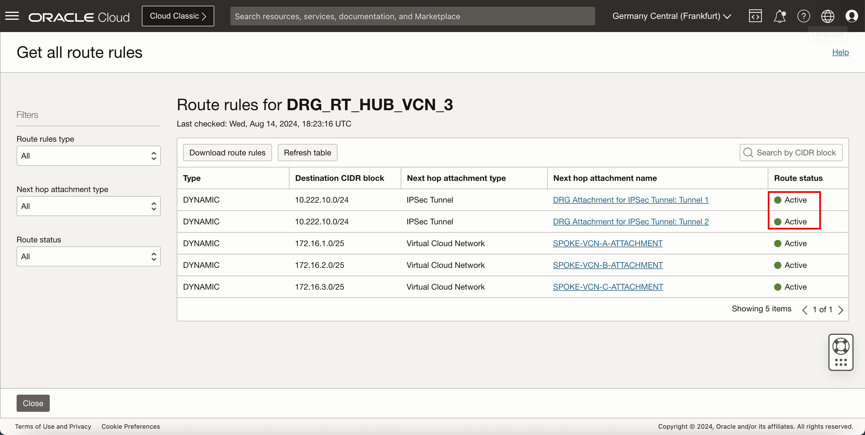
-
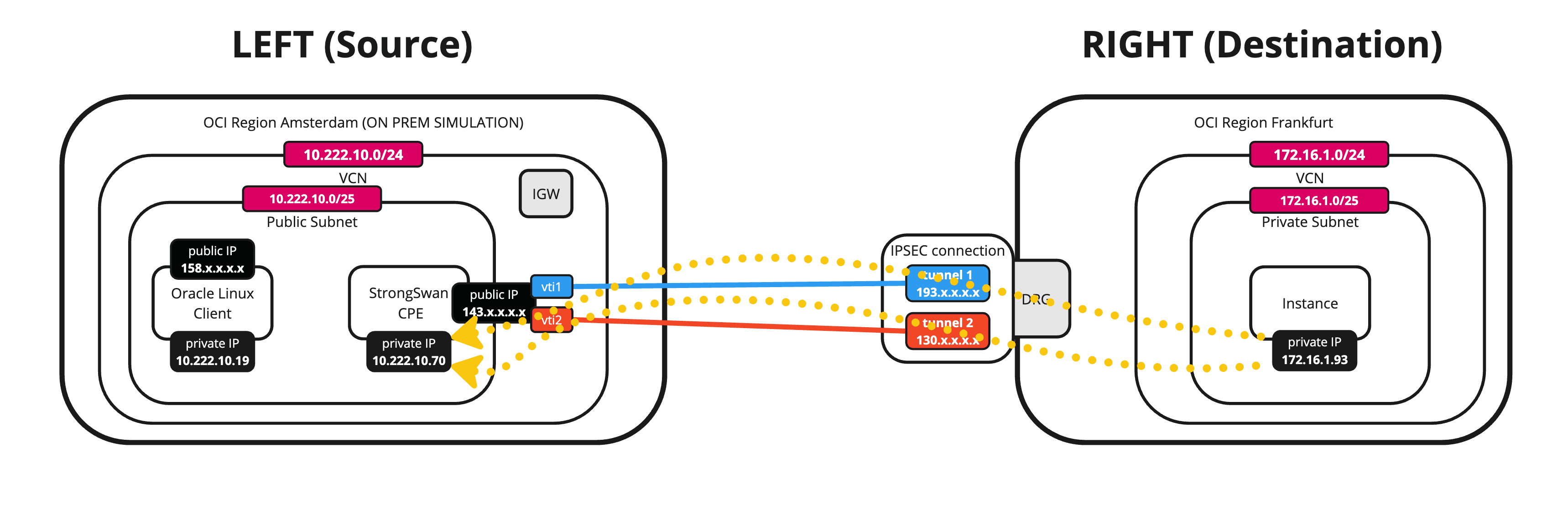
The following image illustrates what we have created so far.
Related Links
Acknowledgments
- Author - Iwan Hoogendoorn (OCI Network Specialist)
More Learning Resources
Explore other labs on docs.oracle.com/learn or access more free learning content on the Oracle Learning YouTube channel. Additionally, visit education.oracle.com/learning-explorer to become an Oracle Learning Explorer.
For product documentation, visit Oracle Help Center.
Set up an Oracle Cloud Infrastructure Site-to-Site VPN with Static Routing Between two OCI Regions
G14487-02
Copyright ©2025, Oracle and/or its affiliates.