A BPMN Flow Object Reference
Get a detailed description of the Business Process Model and Notation 2.0 (BPMN 2.0) flow objects that are supported in Oracle Business Process Management (Oracle BPM) and also Oracle BPM's implementation of the BPMN 2.0 standard. For information about the BPMN standard, including the formal specification, see http://www.bpmn.org.
The BPMN 2.0 flow objects described in this appendix are organized by the different types of tasks your business process must perform.
A.1 Defining the Start and End Point of a Process
Start events are BPMN flow objects that define the starting point of a process. End events, in contrast, define the end point of a process.
This section describes the BPMN 2.0 flow objects that define the start and end of a process.
A.1.1 Introduction to Start and End Events
Start events are BPMN flow objects that define the starting point of a process. There are different types of start events that determine how process instances are created.
End events, in contrast, define the end point of a process. There are different types of end events that determine what happens when the process instance is completed.
Note:
In Oracle BPM, all BPMN processes must have at least one start and one end event.
Because start events define the beginning of a process, they do not have incoming sequence flows. Likewise, end events cannot have outgoing sequence flows.
However, except for the none end and start events, start and end events can have input to and output from other business processes and services.
A.1.1.1 Specifying the Start Events for Different Types of Processes
When you create a new process, Oracle Business Process Composer creates a message start and message end event by default. You can change these defaults depending on the type of business process you want to create. Table A-1 shows the default start and end events for each type of process.
Table A-1 Start and End Events for Each Process Type
| Process Type | Default Start and End Event Types |
|---|---|
|
Asynchronous service |
Message start and end event |
|
Synchronous service |
Message start and end event |
|
Manual process |
None start and end event |
See Introduction to Business Processes for more information on the different types of processes supported by Oracle BPM.
Subprocesses contain none start and end events by default. These are the required start and end events and cannot be changed.
Event subprocesses contain a message start and none end event by default. However, you can change the start event to reflect the type of event you are handling.
A.1.1.2 Using Multiple Start Events in a Process
You can define multiple start points in a BPMN process. Multiple start points allow you to specify multiple ways of creating a process instance, depending on which start event is used.
Figure A-1 shows an example process that contains both a message start and timer start event.
Figure A-1 Using Multiple Start Events within a Process

Description of "Figure A-1 Using Multiple Start Events within a Process"
This process can be invoked using a message event when called from another process or service. It can also be started based on a time interval, invoking the timer start event, if the process instance must be created automatically.
Using multiple start events allows you to have multiple ways of starting a process without having to create two separate processes.
A.1.1.3 Using Multiple End Events in a Process
End events mark the end of a process path. When you have only one end event in your process and the token reaches the end event, the process is stopped when the end event is reached.
Note:
Message end events can only be used to terminate processes initiated by a message start event. Additionally, if you have multiple message end events associated with a message start event, each of these message end events must have the same quantity and type of output arguments.
When using multiple end events, it is possible for different tokens to take different paths within a process. In typical cases, all parallel paths must reach an end event before the process is completed.
However, in the following special cases, a process instance can be stopped before all process paths have completed:
-
Error end event: When an error end event is reached, all process activity is stopped.
Like the error throw event, the error end event stops the flow of a process. See Introduction to the Error End Event for more information.
-
Terminate end event: The terminate end event causes all work on a process to stop immediately.
There is no error handling or other clean up of the running process. See Introduction to the Terminate End Event for more information.
A.1.2 Defining How a Process Instance is Triggered
Oracle BPM supports the following ways of triggering a process instance:
-
Using a message, signal, or timer start event.
See the following sections for more information:
-
Using a none start event followed by a receive task.
The receive task must be configured to create a process instance. See Introduction to the Receive Task for more information.
-
Using a none start event followed by a user task defined with the initiator pattern.
See Introduction to the User Task for more information.
-
Using an event-based gateway that is configured to create a new process instance.
See Using Guided Business Processes to Create Project Milestones for more information.
A.1.3 Introduction to the None Start Event
Use the none start event when no instance trigger is specifically defined. The none start event can be used as a placeholder when the required start event of a process is unknown, not yet defined, or implemented later by process developers.
Figure A-2 shows the default notation for the none start event
None start events also specify the beginning of a process where the process instance is created by another flow object. In general, the none start event does not trigger a new process instance.
However, when used with the following, the none start event does trigger a new process instance:
-
Receive task: The receive task must have the Create Instance property set to true.
-
User task: The user task implemented with the initiator pattern
Similar to other start events, the none start event cannot have incoming sequence flows. It can only have default out-going sequence flows.
Note:
None events are always used to define the beginning of subprocesses.
A.1.3.1 The None Start Event in Context
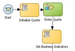
Figure A-3 shows an example of the none start event within the Sales Quote example project. In this example, the none start event defines the start of the process. Additionally, since the process contains a user task implemented with the initiator pattern, the none start event triggers a process instance.
Figure A-3 The None Start Event within the Sales Quote Example Process

Description of "Figure A-3 The None Start Event within the Sales Quote Example Process"
A.1.4 Introduction to the Message Start Event
The message start event triggers a process instance when a message is received. This message can be sent from another BPMN or BPEL process or from a service.
Messages are types of data used to exchange information between processes. Just as data objects are used to define the data used within a project, messages are used to define the data used between processes or between a process and a service.
Figure A-4 shows the default notation of the message start event.
Similar to other start events, the message start event cannot have incoming sequence flows. Message start events require a default outgoing sequence flow.
You can expose a BPMN process as a service that allows other processes and applications to invoke the process. To expose a process as a service, your process must begin with a message start event. Additionally, you must define the input arguments to the process, which are the data objects passed to the message start event. See Defining Process Input and Output for more information.
A.1.4.1 The Message Start Event in Context
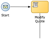
Figure A-5 shows a modified version of the Sales Quote process. Here, the process begins with a message start event that initiates the process instance.
Figure A-5 Message Start Event Within the Sales Quote Example Process
Description of "Figure A-5 Message Start Event Within the Sales Quote Example Process"
A.1.4.2 Using Process Input and Output Arguments
The message start event allows you to specify input and output arguments to a process. These arguments define the message that other processes or services must send to the process during invocation. See Defining Process Input and Output for information on how to configure process input and output arguments.
A.1.5 Introduction to the Signal Start Event
The signal start event is similar to a message start event in that it is based on communication from another process or service. However, the message start event responds to a message sent to a specific process. In contrast, the signal start event is a response to a signal broadcast to multiple processes.
Signals can be broadcast from a BPMN process using the signal throw event. Using a combination of signal throw events and signal start events, you can invoke multiple processes simultaneously.
The signal start and throw events are added to a process by process developers. For information on implementing the signal throw event, see "Introduction to Communicating Between Processes Using Signal Events" in the Developing Business Processes with Oracle Business Process Management Studio.
Figure A-6 shows the default notation for the signal start event.
A.1.6 Introduction to the Timer Start Event
The timer start event triggers the creation of a process instance based on a specific time condition. You can configure the timer start event to trigger a process instance based on the following:
-
A specific date and time.
For example, a process could be triggered on December 31, at 11:59 P.M.
-
A recurring interval.
For example, a process could be triggered every 10 hours, 5 minutes, 32 seconds.
Figure A-7 shows the default notation for the timer start event.
A.1.7 Introduction to the Error Start Event
The error start event is used as the start event of an inline handler. Using inline handlers you can define a separate process flow to handle errors that occur within your process.
Figure A-8 shows the default notation for the none end event.
Note:
Error start events can only be used within inline handlers. They cannot be used within normal process flows.
You can define multiple inline handlers to handle error conditions. However, you cannot define multiple inline handlers that use the same exception.
A.1.8 Introduction to the None End Event
The none end event is used to mark the end of a process path. When a token reaches a none end event, it is consumed. If there are no other tokens within the process instance, the instance is complete.
The none event is used when your process is not required to perform any action after it completes. It can also be used as a placeholder by process analysts, to be changed later during implementation by a process developer.
Figure A-9 shows the default notation for the none end event.
The none end event is always used to mark the end of a subprocess and event subprocess.
A.1.8.1 The None End Event in Context
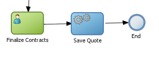
Figure A-10 shows an example of the none end event within the Sales Quote example. In this example, the Sales Quote service task is used to save information about the sales quote to a database.
Figure A-10 The None End Event Within the Sales Quote Example
Description of "Figure A-10 The None End Event Within the Sales Quote Example"
Because no other work can be performed when the token reaches the end of a process, a none end event is used. After all process tokens reach the none end event, the process instance completes.
A.1.9 Introduction to the Error End Event
The end error event is used when the end of a process is the result of an error condition.
Errors end events are typically used with the error boundary event. The error boundary event is used to change the process flow based on a specific error. This flow usually ends using an error end event. See Introduction to the Error Catch Event for more information on using the error intermediate event.
Figure A-11 shows the default notation for the error end event.
For more information, see the Throwing Exceptions in Subprocesses or Reusable Processes in Developing Business Processes with Oracle Business Process Management Studio.
A.1.10 Introduction to the Message End Event
The message end event is used to send a message to another process or service when the process is completed. The message end event is always used with either a message start event or message catch event.
Note:
When creating a process that has multiple end events, you must ensure that any tokens that reach a message end event were created by a message start event. For example, you cannot use a message end event to end a process instance initiated by a timer start event.
Figure A-12 shows the default notation for the message end event.
For information on how to configure process output arguments using message end events, see Defining Process Input and Output.
A.2 Adding User Interaction to Your Process
Many business applications require interaction from process participants within your organization. This interaction can be as simple as entering information into a form or can involve multiple work flows and multiple users.
This section describes the BPMN 2.0 flow objects that are used to model how process participants interact with your business processes. It contains the following sections:
A.2.1 Introduction to Human Workflow
Many end-to-end business processes require manual interaction with the process. For example, users may be required for approvals, exception management, or performing activities required to advance the business process.
Oracle Human Workflow provides comprehensive support for user participation by providing the following features:
-
Manual interactions with processes, including assignment and routing of tasks to the correct users or groups
-
Deadlines, escalations, notifications, and other features required for ensuring the timely performance of a task.
-
Organization, filtering, prioritization, and other features required for process participants to productively perform their tasks.
-
Reports, reassignments, load balancing, and other features required by supervisors and business owners to manage the performance of tasks.
For more information, see Getting Started with Human Workflowin the Developing SOA Applications with Oracle SOA Suite.
A.2.1.1 Introduction to Human Tasks
Human tasks are a component of Oracle Human Workflow. Human tasks allow you to interleave manual interactions with connectivity to systems and services within an end-to-end process flow. Human tasks are responsible for handling all interactions with users or groups participating in the business process. They do this by creating and tracking tasks for the appropriate users in the organization. Users typically access tasks through a variety of clients, including the worklist application, e-mail, portals, or custom applications.
Human tasks allow process developers to define how process participants interact with process-based applications created using Oracle BPM Suite and Oracle Service-Oriented Architecture (SOA) Suite.
Using human tasks, process developers can define the interface and workflow for end user interaction by creating the following:
-
Roles and assignments
-
Deadlines and escalations
-
Presentations
Human tasks are reusable services that can be used within other processes that require the same UI. Human tasks are created using Oracle BPM Studio.
A.2.2 Introduction to the User Task
The user task represents a part of your process where a process participant is required to perform work. This can be a simple interaction, such as entering a form, or part of a more complicated workflow that requires input from multiple process participants.
Figure A-13 shows the default notation for the user task.
In the Oracle BPM Suite, process participants interact with your business application using the Process Workspace. The specific user interface elements, including the screens and panels that process what participants see, are created using human tasks.
When designing a process, process analysts often add the user task to a process diagram. Process developers then create the necessary human tasks and implement them as part of creating the overall process-based business application.
When a token reaches a user task, the corresponding human task is performed. The token waits until the human task is completed before continuing to the next flow object.
See How to Assign a Business Catalog Component to a Flow Object for procedures on how to assign elements from the business catalog to a user task.
For information about implementing user tasks, see "Using Human Tasks" in the Developing Business Processes with Oracle Business Process Management Studio.
Similar to other flow objects, the user task may contain incoming and outgoing data associations.
User tasks may also contain incoming and default outgoing sequence flows.
A.2.2.1 The User Task in Context
In the Sales Quote example, the Enter Quote task, shown in Figure A-14, represents entering information about the quote.
After the user enters information about the sales quote, the process flow passes through the outgoing sequence flow to the next flow object in the process.
A.2.2.2 Using Interactive Activities
Oracle BPM Studio allows you to add interactive activities to a process directly from the component palette. Interactive activities are short cuts based on the task routing and approval features of Oracle Human Workflow. See " Getting Started with Human Workflow" in Developing SOA Applications with Oracle SOA Suite for more information.
Table A-2 shows the interactive activities that are available in the Oracle Business Process Composer component palette.
Table A-2 Interactive Activities
| Pattern | Description |
|---|---|
|
Complex |
Uses a complex routing flow that is defined within the human task. |
|
Management |
Uses the management chain pattern where the assignee is set to the management chain pattern for the process participant belonging to the group or role assigned to the swimlane. |
|
FYI |
Bases assignment on the participant, role, or group defined in the swimlane. Similar to the user interactive activity, but the FYI activity does not wait until completion before continuing. |
|
Group |
Uses the group vote pattern. The assignee for the task is automatically set to the role or group associated with the lane. This interactive activity can only be added to swimlanes that are assigned to roles or groups. |
|
Initiator |
The initiator pattern is used to create a process instance. |
A.2.3 Introduction to the Manual Task
The manual task represents a task performed by process participants that is outside the scope of Oracle BPM. Manual tasks are used as placeholders within your process to show work that is not managed by the BPMN service engine at runtime. Additionally, manual tasks do not appear in the Process Workspace application.
Note:
Manual tasks are not managed by Oracle BPM. The Oracle BPM runtime does not track the start and completion of the manual task.
Figure A-15 shows the default notation for the manual task.
Manual tasks can only have one default incoming and one default outgoing sequence flow.
Unlike most BPMN 2.0 flow objects, the manual task does not allow you to manipulate data objects. Data objects associated with the previous flow element are passed through as is to the next flow element.
A.2.3.1 The Manual Task in Context
In the context of the Sales Quote example, a manual task can be added for printing and signing a copy of a formal contract as shown in Figure A-16.
In this example, signing the formal contract is something that you may want to explicitly show as part of your business process. However, because it is not managed by the BPMN Service Engine, a manual task is used.
A.2.4 Introduction to the Update Task
The update task is used to perform an operation on one or more Human Tasks. For example, you can use the update task to perform actions like reassigning a task to another user.
Figure A-17 shows the default notation for the update task.
A.3 Communicating With Other Processes and Services
Oracle BPM allows you to define interactions across business processes within a process-oriented application. The following sections describe the BPMN flow objects used to model communication between processes.
This section describes how to use these flow objects to create process models using Oracle Business Process Composer. For information on how to implement these flow objects within a process-based application, see Developing Business Processes with Oracle Business Process Management Studio.
A.3.1 Introduction to the Service Task
The service task allows you to communicate with other processes and services. Process analysts can add the service task when they know that a process must invoke an external service or process.
Process developers can then implement the necessary services. You can use the service task to invoke the following:
-
Other BPMN processes
-
BPEL processes
-
SOA service adapters
-
Mediators that are exposed as services
See How to Assign a Business Catalog Component to a Flow Object for information for procedures about to assign elements from the business catalog to a service task.
The service task has similar behavior to the send and receive task pair and the message throw and catch event pair. The primary difference is that the service task is used to invoke processes and services synchronously. When the service task invokes a process or service, the token waits at the service task until a response is returned. After the response is received, the token continues to the next sequence flow in the process.
See "Using Service Tasks to Invoke Synchronous Operations in Services and BPMN Processes" in Developing Business Processes with Oracle Business Process Management Studio for more information on how to implement the service task with these types of processes and services.
Figure A-18 shows the default notation for the service task.
A.3.1.1 The Service Task in Context
Figure A-19 shows an example of the service task used to save the finalized sales quote to a database.
Figure A-19 The Service Task within the Sales Quote Example Process

Description of "Figure A-19 The Service Task within the Sales Quote Example Process"
A.3.2 Introduction to the Notification Task
The notification task is similar to the service task. It uses a predefined service to perform different types of notification. You can use expressions to determine the users or groups who receive notifications generated by the notification task.
These different types of notification are:
-
IM: Send an instant message to a user or group.
Figure A-20 shows the default notation of the IM notification task.
Figure A-20 The Instant Message Notification Task

Description of "Figure A-20 The Instant Message Notification Task" -
Email: Sends an email a user or group.
You can also include email attachments. Figure A-21 shows the default notation of the email notification task
-
SMS: Sends an SMS message to a user.
Figure A-22 shows the default notation of the SMS notification task
-
User: Sends a notification to a user based on the available notification types.
For example, if a user has both SMS email configured, the notification task sends both. Figure A-23 shows the default notation of the User notification task.
A.3.3 Introduction to the Call Activity
The call activity allows you to call a reusable process from within the current process. The process being called becomes a child process of the calling process. When calling a reusable process, the call activity of the parent process waits until the child process completes before continuing.
Figure A-24 shows the default notation for the call activity.
See Introduction to Reusable Processes (Reusable Subprocesses) for more information.
Data objects of the parent process are not automatically available to the reusable process. Data objects must be passed to and from the child process using argument mapping of the call activity.
A.3.4 Introduction to the Send Task
The send task sends a message to a system or process outside the current process. After this message is sent, the task is complete and the running of the process continues to the next task in the process flow.
The send task is frequently paired with the receive task to invoke a process or service and receive a response in return. The send and receive tasks are used to invoke processes and services asynchronously. If you are invoking a process or service synchronously, use the service task.
Note:
The send and receive tasks perform functions similar to the throw and catch message events. However, you cannot use the send task to invoke a process that is initiated with a message start event.
Figure A-25 shows the default notation for the send task.
For information on implementing the send task to invoke a process or service, see "Using Send and Receive Tasks to Define a Synchronous Operation in a BPMN Process" in Developing Business Processes with Oracle Business Process Management Studio.
For information about using the send and received tasks to communicate between processes, see Using the Send and Receive Tasks to Communicate Between Processes.
A.3.5 Introduction to the Receive Task
In contrast to the send task, the receive task waits for a message from a system or process outside the current process. After this message is received, the task is complete and the running of the process continues to the next task in the process flow.
Figure A-26 shows the default notation for the receive task.
For information about implementing the send task to invoke a process or service, see "Using Send and Receive Tasks to Define a Synchronous Operation in a BPMN Process" in Developing Business Processes with Oracle Business Process Management Studio.
For information about using the send and receive tasks to communicate between processes, see Using the Send and Receive Tasks to Communicate Between Processes.
A.3.5.1 Starting a Process with the Receive Task
You can use the receive task to trigger the start of a process. This is useful when you want to invoke a process from another process using a send task.
To start a process using the receive task, the following conditions must be met:
-
The receive task is preceded by an none start event.
-
Your process does not contain any other start events.
-
The Create Instance property is enabled.
A.3.6 Introduction to the Message Throw Event
The message throw event allows you to send a message to another process or service.
Figure A-27 shows the default notation for the message throw event.
The throw message event is used to invoke the following types of processes and services:
-
Other BPMN processes
-
BPEL processes
-
SOA service adapters
-
Mediators that are exposed as services
Process analysts may add message throw events to a process to define where a process must invoke another process or service. However, process developers are typically responsible for implementing the connectivity with other processes. Additionally, they are typically responsible for creating and implementing the services invoked by the message throw event.
For information about how to implement message throw events, see "Communicating With Other BPMN Processes and Services Using Message Events" in Developing Business Processes with Oracle Business Process Management Studio.
Message throw events are often used to invoke other BPMN processes by calling the message start event of another process. See Introduction to the Message Start Event for more information.
Message throw events are also frequently used with message catch events to receive a response from the process or service invoked. However, they are always used asynchronously. After the message throw event sends a message to another process or service, the token immediately moves to the next flow object of the process.
If your process receives a response synchronously, use the service task to invoke the process or service. See Introduction to the Service Task for more information.
Note:
The send and receive tasks perform functions similar to the throw and catch message events. However, you cannot use the message throw event to invoke a process that is initiated with a message receive task.
A.3.7 Introduction to the Message Catch Event
The message catch intermediate event allows you to receive a message from another process or service.
Figure A-28 shows the default notation for the message catch event.
The message catch event is frequently used with the message throw event to communicate with another BPMN process. See Using Message Throw and Catch Events to Communicate Between Processes for information on how message throw events with message catch event.
For information about how to implement message throw events, see "Communicating With Other BPMN Processes and Services Using Message Events" in Developing Business Processes with Oracle Business Process Management Studio.
A.4 Adding Business Logic Using Oracle Business Rules
This section describes how to use the business rule task to incorporate Oracle Business Rules within your business processes.
For information about working with Oracle Business Rules using Oracle Business Process Composer, see Using Oracle Business Rules.
A.4.1 Introduction to Oracle Business Rules
Business rules are statements that describe business policies or describe key business decisions.
A.4.2 Introduction to the Business Rule Task
The business rule task allows you to incorporate Oracle Business Rules within your process.
Figure A-29 shows the default notation for the business rule task.
There are two primary use cases for incorporating Oracle Business Rules within your business process.
-
Using structural rules
Structural rules allow you to perform calculations used within your business process. For example, you can use a business rule to calculate a credit score.
-
Using operative rules
Operative rules are used to make changes to the flow of your process. A typical use of an operative rule is to perform a check of the rule conditions within the rules catalog. Then, as part of the output data association, assign a value to a data object using an expression.
In this scenario, the business rule task is immediately followed by a gateway that is used to branch the process path according to the value of the data object.
for information about how an operation rule is used, see The Business Rule Task in Context.
For information on procedures about assigning elements from the business catalog to a business rule tasks, see How to Assign a Business Catalog Component to a Flow Object.
A.4.2.1 The Business Rule Task in Context
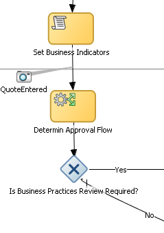
Figure A-30 shows an example of the business rule task within the Sales Quote example.
Figure A-30 The Business Rule Task within the Sales Quote Example Process
Description of "Figure A-30 The Business Rule Task within the Sales Quote Example Process"
A.5 Controlling Process Flow Using Sequence Flows
Sequence flows define the order or sequence that work is performed within a process. Sequence flows connect the flow objects within your process and determine the path a process token follows through your process.
This section describes how to use sequence flows to define the behavior of your business process.
A.5.1 Introduction to Sequence Flows
Incoming sequence flows are the sequence flows that lead into a flow object. Outgoing sequence flows are the sequence flows that determine the process path out of a flow object.
Most flow objects contain both incoming and outgoing sequence flows. Exceptions to this are start and end events. Start events can only contain outgoing sequence flows. End events can only contain incoming sequence flows. Additionally, event subprocesses do not have either incoming or outgoing sequence flows.
A.5.2 Introduction to Unconditional Sequence Flows
Unconditional sequence flows represent the typical path between two flow objects. Default sequence flows are displayed as a line with and arrow as shown in Figure A-31.
Figure A-31 The Unconditional Sequence Flow
Description of "Figure A-31 The Unconditional Sequence Flow"
Most flow objects can contain only one default out going sequence flow. Only parallel gateways can contain multiple unconditional sequence flows, which represent the parallel paths of your process.
Exclusive, inclusive, and conditional gateways cannot have unconditional outgoing sequence flows. These gateways use conditional and default sequence flows to determine the flow of your process.
A.5.3 Introduction to Conditional Sequence Flows
Conditional sequence flows are used to control the flow of a process based on certain conditions. Like unconditional sequence flows, conditional sequence flows are displayed by an arrowed line.
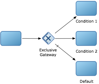
Figure A-32 shows two outgoing conditional sequence flows and a default sequence flow.
Figure A-32 Conditional and Default Sequence Flows
Description of "Figure A-32 Conditional and Default Sequence Flows"
Not all flow objects can use outgoing conditional sequence flows. Only the following types of gateways can have outgoing conditional sequence flows:
-
Exclusive gateways
-
Inclusive gateway (split)
The conditions used within a conditional sequence flow are defined using expressions. For information about using the expression editor to define expressions, see Using Expressions to Control Data .
A.5.4 Introduction to Default Sequence Flows
Like conditional sequence flows, default sequence flows are used as outgoing sequence flows to exclusive, inclusive, and conditional gateways. Default sequence flows represent the path your process takes out of these gateways when none of the conditions evaluate to true.
Default sequence flows are represented by an arrow with a tic mark on one end, as shown in Figure A-32.
A.6 Controlling Process Flow Using Gateways
Gateways are flow elements that define the flow of your process. Gateways determine the path a token takes through a process. They define control points within your process by splitting and merging paths.
This section describes how to use gateways to control process flow and behavior.
A.6.1 Introduction to Gateways
Gateways define control points within your process by splitting and merging paths. When possible, gateways are used for paths that are exceptions to or deviate from the default path of the process.
A.6.1.1 Split-Merge Pairs
The following gateways require a split-merge pair:
-
Parallel gateway
-
Inclusive gateway
-
Complex gateway
When you add one of these gateways to a BPMN process, Oracle BPM Studio automatically creates the split and merge flow objects.
Although the merge portion of the gateway is required, you do not have to ensure that all paths out of the split return to the merge.
Although it is possible to have process paths that split at a gateway without merging through the gateway, this is not usually good practice. For more details on the merge behavior of gateways, see the following sections for each gateway type.
Note:
If you delete the merge gateway from a process, the corresponding split gateway is also deleted.
A.6.2 Introduction to the Exclusive Gateway
The exclusive gateway allows you to split your process into two or more paths. However, the process only continues down one of these paths even if multiple outgoing sequence flows are present. Exclusive gateways can have conditional outgoing sequence flows and must have at least one default outgoing sequence flow.
You can define expressions that are used to determine if your process continues down a conditional sequence flow. See Using Expressions to Control Data for more information.
If your process has multiple outgoing sequence flows for an exclusive gateway, you can define the order in which they are evaluated. The order of evaluation is configured in the properties of the exclusive gateway.
If you have an exclusive gateway where more than one conditional sequence flow evaluates to true, the process continues down the first conditional sequence flow determined by this order.
Unlike other gateways, the exclusive gateway does not require a corresponding merge to be explicitly defined in your process after splitting.
Figure A-33 shows the default notation for the exclusive gateway.
A.6.2.1 The Exclusive Gateway in Context
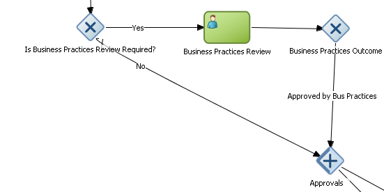
Figure A-34 shows an example of the exclusive gateway used within the Sale Quote example. Here, the exclusive gateway is used to evaluate whether a review of business practices is required.
Figure A-34 The Exclusive Gateway within the Sales Quote Example Process
Description of "Figure A-34 The Exclusive Gateway within the Sales Quote Example Process"
This evaluation is determined by the expression defined for the outgoing conditional sequence flow. If this evaluates to true, then the process flow proceeds down the Yes path. If it evaluates to false, then the process flow proceeds down the path of the default outgoing sequence flow.
A.6.2.2 Splitting and Merging Exclusive Gateways
When a token reaches an exclusive gateway the outgoing conditional sequence flows are evaluated until one of them evaluates to be true. You can define the specific order in which these are evaluated by configuring a property for the exclusive gateway.Based on this configuration, when the first conditional sequence flow evaluates to true, the token moves down this outgoing sequence flow to the next flow object. If you have multiple outgoing conditional sequence flows, you can determine the order in which they are evaluated.If none of the outgoing conditional sequence flows evaluate to true, then the token moves down the default outgoing sequence flow. Therefore, you must define a default outgoing sequence flow for the exclusive gateway.
The exclusive gateway can also merge incoming sequence flows. However, there is no synchronization with other tokens that may be coming from other paths within the process flow.
Note:
If other tokens arrive at an exclusive gateway merge, then they are also passed through as is. If you are synchronizing tokens or perform evaluations on incoming sequence flows, you should use a different type of gateway.
A.6.3 Introduction to the Inclusive Gateway
The inclusive gateway allows you to split your process into two or more paths. Unlike the exclusive gateway, however, a token may flow down one or more of these paths depending on how the outgoing conditional sequence flows are evaluated.
You must define at least one default sequence flow for the inclusive gateway split. You can have multiple outgoing conditional sequence flows for an inclusive gateway split. The token proceeds along only those sequence flows that evaluate to true. If none of the sequence flows evaluate to true, then the token passes along the default sequence flow.
Figure A-35 shows the default notation for the inclusive gateway split.
Figure A-36 shows the default notation for the inclusive gateway merge.
A.6.3.1 Splitting and Merging Inclusive Gateways
The inclusive gateway splits a process similar to the exclusive gateway, but allows tokens to proceed down multiple outgoing sequence flows. When a token arrives at an inclusive gateway, the expressions of its conditional sequence flows are evaluated.
Next, a token is generated for each of the conditional sequence flows that evaluate to true. A token is generated for the default sequence flow only if none of the conditional sequence flows evaluate to true.
These tokens are joined at the merge of the inclusive gateway. When a token reaches the merge gateway, it waits until all of the tokens generated by the split have reached the merge. After all of the tokens have reached the merge of the inclusive gateway, the merge is complete, and the token continues to the next sequence flow after the gateway.
A.6.4 Introduction to the Parallel Gateway
The parallel gateway allows you to split your process into two or more paths when you want your process flow to follow all paths simultaneously. The parallel gateway is useful when your process must perform multiple tasks in parallel.
Figure A-37 shows the default notation for the parallel gateway split.
Figure A-38 shows the default notation for the parallel gateway merge.
A.6.4.1 The Parallel Gateway in Context
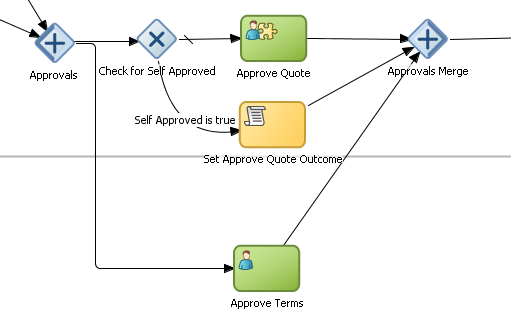
The Sales Quote example uses a parallel gateway during the approval stage of the process. Figure A-39 shows how the parallel gateway is used to perform two process paths simultaneously.
In this example, two different process paths are executed at the same time.
A.6.4.2 Splitting and Merging Parallel Gateways
When a token reaches a parallel gateway, the parallel gateway creates a token for each outgoing sequence flow. The split of the parallel gateway does not evaluate outgoing sequence flows.
You can also use the parallel gateway to merge process paths split by the parallel gateway. The merge of the parallel gateway waits for a token to arrive from each of the incoming sequence flows. After all tokens arrive, only one token is passed to the outgoing sequence flow.
Note:
Design your process so that a token arrives for each incoming sequence flow for the merging parallel gateway. If you do not, your process can freeze if the merge is expecting tokens that do not arrive.
A.6.5 Introduction to the Complex Gateway
The complex gateway splits a process similar to an inclusive gateway. However, it allows you to define an activation condition that determines if the instance can continue even if not all of the tokens have arrived at the complex gateway merge.
For example, you can configure a complex gateway to continue after two or more tokens have arrived. If only two out of the possible conditions in the inclusive gateway evaluate to true the process instance continues to the next activity. However, because the inclusive gateway immediately evaluates all the conditional sequence flows, all of the flow objects in these process paths are also run.
Figure A-40 shows the default notation for the complex gateway split.
Figure A-41 shows the default notation for the complex gateway merge.
A.6.6 Introduction to the Event-Based Gateway
The event-based gateway allows you to branch your process flow based on the possibility that an event may occur. Depending on the context, this may be one of several types of events.
The event-based gateway allows you to anticipate the possibility that several types of events may occur at a specific point in your process. It is similar to the exclusive gateway, but instead of choosing a path based on expressions, the event-based gateway chooses a path based on the occurrence of an event within your process.
For example, in an order processing process, you may reach a point in your process when there is no stock currently available. The process may have to wait until stock is available, but cannot wait indefinitely. By using an event-based gateway, your process can wait for a message saying new stock has been received (using a message catch event) or it can continue if no message is received after a certain amount of time has passed (using a timer event).
Figure A-42 shows the default notation for the event-based gateway.
The event-based gateway is different from other gateways in that decisions about process flow are based on an event rather than data-specific conditions.
The event-based gateway is composed of the following:
-
The event-based gateway
-
Two or more target events
These can be of the following types:
-
Message catch events
When initiating a process using a message catch event, the process must be invoked using a message throw event.
-
Timer catch events
Generally only one timer event is used following an event-based gateway.
-
Receive tasks
You can use the receive task to initiate a process instance following an event-based gateway. However the process must be invoked from a send task within the calling process.
Note:
You cannot mix message events and receive tasks within the same event-based gateway.
-
The target elements can only have incoming sequence flows from the event-based gateway. They cannot have sequence flows from other parts of the process.Although the event-based gateway allows you to plan that multiple events may occur in your process, within the process instance, only one event is triggered. When the first event in the event-based gateway is triggered, the path that comes after that event is followed.
When you add an event-based gateway to a process, by default it is created with a timer and message catch event.
Note:
If you delete an event-based gateway, any outgoing sequence flows are also deleted. The associated events are not deleted.
A.6.6.1 Starting a Process with an Event-Based Gateway
You can also use an event-based gateway at the beginning of a process to create a new process instance. This is similar to having multiple start events within a process.
To allow an event-based gateway to create a new process instance, you must ensure the following:
-
You have enabled the Initiate property of the event-based gateway.
-
There are no incoming sequence flows to the event-based gateway.
Although the event-based gateway can be used to create a new process instance, it does not accept data input from another process. Any data that must be passed to the process instance must be configured using the target events.
A.7 Controlling Process Flow Using Intermediate Events
Unlike start and stop events, intermediate events occur during the flow of your process.
This section describes intermediate events and describes how to use them to control the flow and behavior of your process.
A.7.1 Introduction to Intermediate Events
There are two types of intermediate events:
-
Normal flow events
Normal flow events occur within the typical flow of your process.
-
Boundary events
Boundary events trigger an interruption with your process. Boundary events are associated with flow objects and can be configured to interrupt their usual behavior.
Boundary events behave similar to sequence flows in that they are used to determine the path a process takes between flow objects.
Boundary events can be divided into two types: interrupting and non interrupting.
A.7.2 Introduction to the Timer Catch Event
Timer catch events allow you to control the flow of your process using a time condition. Possible uses of the time catch event include:
-
Creating a delay before running an activity
-
Configuring a deadline for an activity
-
Configuring a deadline for a process
-
Triggering additional activities after an elapsed time
Figure A-43 shows the default notation for the timer catch event.
You can use timer events as boundary events on an activity. Timer events can be defined as either interrupting or non interrupting boundary events.
When an interrupting timer event fires, the token leaves the main process flow to follow the flow the timer event defines. The flow that an interrupting timer event defines can return directly to the main process flow.
When a non interrupting event fires, a copy of the token is created and passes through the flow the timer event defines. The flow that a non interrupting event defines cannot return to the main process flow.
A.7.3 Introduction to the Error Catch Event
Error catch events are intermediate events used to handle an error that occurs within your process flow.
Note:
You can also use inline handlers to handle error conditions that occur within your process.
Error catch events are always used as boundary events and can be attached to the following:
-
Service Tasks
-
Call Activities
-
User Tasks
-
Send Tasks
-
Receive Tasks
-
Script Tasks
-
Rules Tasks
-
Subprocesses
Error catch events are always interrupting, meaning that they interrupt the usual flow of a process.
Figure A-44 shows the default notation for the error catch event attached as a boundary event on a service task.
Figure A-44 The Error Catch Event as a Boundary Event on a Service Task

Description of "Figure A-44 The Error Catch Event as a Boundary Event on a Service Task"
When a service or process fails with an error, the error catch event is triggered. This causes the process flow to follow the path of the outgoing sequence flow of the error catch event.
You can use this flow to define how you handle the error. This is handled in two ways:
-
The process flow returns to the main process flow.
Any work that must be performed is handled within the error process flow before returning to the main flow.
Note:
If the boundary event is non-interrupting, the boundary flow cannot return to the main flow.
-
The process flow continues to an end event.
The process is stopped immediately. Process control is returned to the service or process that initiated the process.
A.8 Using Subprocesses in Oracle BPM
You can use subprocesses to organize you business processes. Subprocesses allow you to group functional areas of your process together and also make your processes more readable.
Oracle BPM supports the following types of subprocesses:
-
Reusable processes
-
Embedded (also called inline) subprocesses
-
Event subprocesses (also called inline handlers)
A.8.1 Introduction to Reusable Processes (Reusable Subprocesses)
Oracle BPM supports a type of process called reusable process. In BPMN terminology, this is sometimes referred to as a reusable subprocess. Reusable processes allow you to create processes that can be called from other BPMN processes.
Reusable processes allow you to create processes that can be called from other BPMN processes. For example, all your processes may have to charge a credit card, so you can create a charge credit card reusable subprocess
Reusable processes have the following characteristics:
-
Must start with one none start event.
-
Can contain multiple end events.
-
Can only be called by other BPMN processes.
A.8.2 Introduction to Embedded Subprocesses (Inline Subprocesses)
Embedded subprocesses allow you to group BPMN flow objects together to make your process more readable. In Oracle BPM, subprocesses are embedded subprocesses. Subprocesses are contained as part of the parent subprocess. Embedded subprocesses must begin with a start none event and must end with a none end event.
Embedded subprocesses can be expanded or collapsed. Figure A-45 shows how a collapsed subprocess appears within a process.
Figure A-45 Example of a Collapsed Embedded Subprocess

Description of "Figure A-45 Example of a Collapsed Embedded Subprocess"
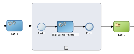
Figure A-46 shows how an expanded embedded subprocess appears within a process. When an embedded subprocess is expanded, you can edit the flow objects within it. You can also click and drag the edge of the embedded subprocess window to make the window larger or smaller.
Figure A-46 Example of an Expanded Embedded Subprocess
Description of "Figure A-46 Example of an Expanded Embedded Subprocess"
Similar to other types of processes, embedded subprocesses can have start and end events and contain a separate process flow. An embedded subprocess must begin with a none start event and end with a none end event. Embedded subprocesses cannot contain swimlanes.
Embedded subprocesses also behave similar to activities. They can have incoming and outgoing sequence flows. They also contain data associations that define the data objects used within the embedded subprocesses.
Embedded subprocesses can also contain timer, message, and error boundary events.
If necessary, your process can contain nested embedded subprocesses. However, use nested embedded subprocesses only when necessary to make your process more readable.
A.8.2.1 Embedded Subprocesses and Sequence Flows
The flow objects within an embedded subprocess cannot have sequence flows that connect to flow objects outside the subprocess.
Similar to other flow objects, embedded subprocesses have incoming and outgoing sequence flows.
A.8.2.2 Embedded Subprocesses in Context
Figure A-47 shows an example of a embedded subprocess. In this example, an embedded subprocess is used to group the service task used to process a sales quote.
Figure A-47 Example of an Embedded Subprocess
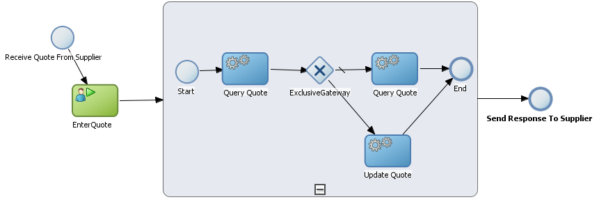
Description of "Figure A-47 Example of an Embedded Subprocess"
A.8.2.3 Looping Embedded Subprocesses
You can configure a subprocess to numerous times within the context of a process flow. This is something that a process analyst should consider when designing a process, but the implementation is performed by process developers.
Note:
Looping cannot be configured using Oracle Business Process Composer. You must used Oracle BPM Studio to configure the looping property of an embedded subprocess. See Developing Business Processes with Oracle Business Process Management Studio for more information.
A.8.3 Introduction to Event Subprocesses (Event Handlers)
An event subprocess are a type of subprocess that allows you to model possible conditions that happen outside of a normal process flow. Event subprocesses are also called event handlers.
Event subprocesses can have the following start events:
-
Error start
-
Timer start
-
Message start
When you add an inline handler to your process, by default it is created with a message start event. You can change the type of start event if necessary.
Note:
Inline handlers can only contain one start event. However, you can have multiple inline handlers within your process.
A.9 Changing the Value of Data Objects in Your Process
This section describes how to use the script task to change the values of data objects within your process.
See Working with Data Objects and Data Associations for general information about data objects.
A.9.1 Introduction to the Script Task
The script task is used to change values of data objects within your process. The script task is used when you want to show this change explicitly within your business process or when you must change the values of data objects outside of another flow object. It is often used to set initial values of data objects at the beginning of a process.
Figure A-48 shows the default notation for the script task.
Script tasks are added to a process by process developers who are responsible for defining the behavior of data objects within a process and process-based application.
A.9.1.1 The Script Task in Context
Figure A-49 shows two examples of the script task used at the beginning of the Sales Quote example. The Sales Quote example uses a script task to set initial values for data objects when the process instance is created and to set values for several business indicators.
Figure A-49 The Script Task within the Sales Quote Example
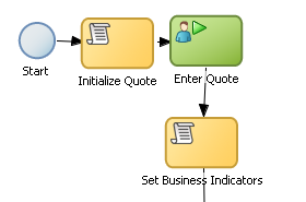
Description of "Figure A-49 The Script Task within the Sales Quote Example"
Project data objects are data objects that you define in a project. All processes within a project have access to the data object defined, though the value changes according to the process using them. In addition, the engine stores the value of those marked as business indicators to the process analytics databases if the project is configured to use them.
Figure A-50 shows the data associations used to set initial values for the business indicators.
Figure A-50 Data Associations Used by the Set Business Indicators Script Task
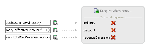
Description of "Figure A-50 Data Associations Used by the Set Business Indicators Script Task"
As with other flow objects that accept data associations, you can use expressions to change the values of data objects. Figure A-51 shows how an expression is used to change the value of the discount project variable.
Figure A-51 Expression Used to Change the Value of Discount Project Variable

Description of "Figure A-51 Expression Used to Change the Value of Discount Project Variable"
Note:
If you implemented the script task using transformations using BPM Studio, they are not visible when opening the BPM project in Oracle Business Process Composer.
