9 Using Correlation Sets and Message Aggregation
This chapter includes the following sections:
9.1 Introduction to Correlation Sets in an Asynchronous Service
Correlation sets provide a method for directing web service responses to the correct BPEL process service component instance. You can use correlation sets to identify asynchronous messages to ensure that asynchronous callbacks locate the appropriate client. You define correlation sets when interactions are not simple invoke-receive activities.
Correlation sets are a BPEL mechanism that provides for the correlation of asynchronous messages based on message body contents. To use this method, define the correlation sets in your BPEL process. This method is designed for services that do not support WS-Addressing or for certain sophisticated conversation patterns, for example, when the conversation is in the form A > B > C > A instead of A > B > A.
9.1.1 Scenarios for Using Correlation Sets
Correlations enable you to associate asynchronous messages based on message body contents. Note that not all business scenarios require correlations:
-
Synchronous calls do not require correlations because the conversation context is maintained in the stack or across a TCP connection.
-
Consenting BPEL processes typically correlate messages using WS-Addressing headers to pass tokens that act like session cookies in a web application. For more information, see Using WS-Addressing in an Asynchronous Service.
Correlation is required in the following scenarios. In these cases, a BPEL process must be configured to view some content of the message to select the correct process instance to receive the message.
-
When using an asynchronous service that does not support WS-Addressing.
-
When receiving unsolicited messages from another system.
-
When the message travels through several services and the response is solicited by the initial service from the last service directly.
-
When communicating through files.
9.1.2 Understanding Correlation Set Contents and Concepts
This section provides an overview of key correlation set concepts.
The correct BPEL instance using correlation sets is obtained as follows:
-
A BPEL process provides a construct called a correlation set to allow for custom correlation.
-
A correlation set is a collection of properties used by the BPEL process service engine to identify the correct process to receive a message.
-
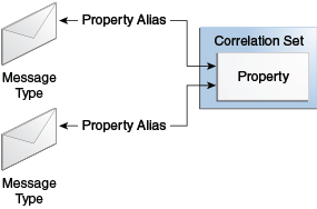
Each property in the correlation set can be mapped to an element in one or more message types through property aliases. Figure 9-1 provides an overview.
Note the following key correlation guidelines:
-
Only the process receiving the message is concerned about correlation. As long as the sending service includes sufficient information in the message to correlate it with previous activities, the sender does not need to be aware that correlation is occurring.
-
Correlation properties must be unique for the duration of the life of the BPEL process that sets them.
-
Ensure that no two processes are working with the same correlation tokens. For example, using social security numbers to correlate an expense claims process is not recommended if you start two separate instances of the process.
-
Properties can be made up values or actual business identifiers such as purchase orders or numbers. They do not need to be strings; they can be any reasonable XML type.
Key correlation concept attributes are as follows. You set these attributes in Oracle JDeveloper when designing a correlation set with the Correlation wizard:
-
An initiate attribute is set as follows:
-
yes: The correlation set is initiated with the values of the properties available in the message being transferred.
-
no: The correlation set validates the value of the property available in the message.
-
-
A pattern attribute is set as follows:
-
in (for BPEL 1.1) or response (for BPEL 2.0): The correlation property is set and validated on the incoming message.
-
out (for BPEL 1.1) or request (for BPEL 2.0): The correlation property is set and validated on the outgoing BPEL message.
-
out-in (for BPEL 1.1) or request-response (for BPEL 2.0): The correlation property is set and validated on both incoming and outgoing messages.
-
-
Property aliases map a global property to a field in a specific message part. This action enables the property name to become an alias for the message part and location. The alias can be used in XPath expressions.
9.1.3 Overview of Correlation Set Creation
Table 9-1 provides an overview of the steps for creating a correlation set. References to the pages of the Correlation wizard on which you perform these steps and examples of values to set are provided.
Table 9-1 Correlation Set Creation Overview
| Step | Correlation Wizard Page | Example |
|---|---|---|
|
Create a correlation set with property names and types to correlate the exchange. |
Set this information on the Correlation wizard - Define Correlation Set page. See Figure 9-2. |
Create a phonenumber correlation set with property names and types:
|
|
Add the correlation to the invoke or receive activity that begins the conversation and set Initiate to yes. |
Select the activity and set the Initiate attribute on the Correlation wizard - Initiate Settings page. See Figure 9-3. |
Select the internalReceive receive activity and set Initiate to yes. |
|
Create property alias mappings to appropriate elements in each message. They must have the same value in both messages of the conversation. The elements can be different names and in different structures in the two messages, but they must contain the same value for correlation to work. |
Set this information on the Correlation wizard - Property Aliases page. See Figure 9-7. Two editors available on this page enable you to create the property alias mappings:
|
Define the property aliases to populate the correlation set property values at runtime:
|
|
Add the same correlation set with its property to additional activities. Do not set them to initiate. The BPEL process uses this to select the correct process instance. Set the pattern accordingly. |
Set on the Activity Correlation Editor - Initiate Tab. See Figure 9-10. |
Select the internalCallback invoke activity:
|
9.2 Creating Correlation Sets in Oracle JDeveloper
You can create correlation sets on the following activities and branches.
-
Receive activity
-
Reply activity
-
Invoke activity
-
onMessage branch
-
onEvent branch
There are two methods for creating correlations sets in Oracle JDeveloper:
-
Automatically through the Correlation wizard in an activity
-
Manually through the Correlations tab in an activity
9.2.1 How to Create a Correlation Set with the Correlation Wizard
To create a correlation set with the Correlation wizard:
-
Right-click an applicable activity (such as a receive activity), and select Setup Correlation.
The Correlation wizard - Define Correlation Set page is displayed.
-
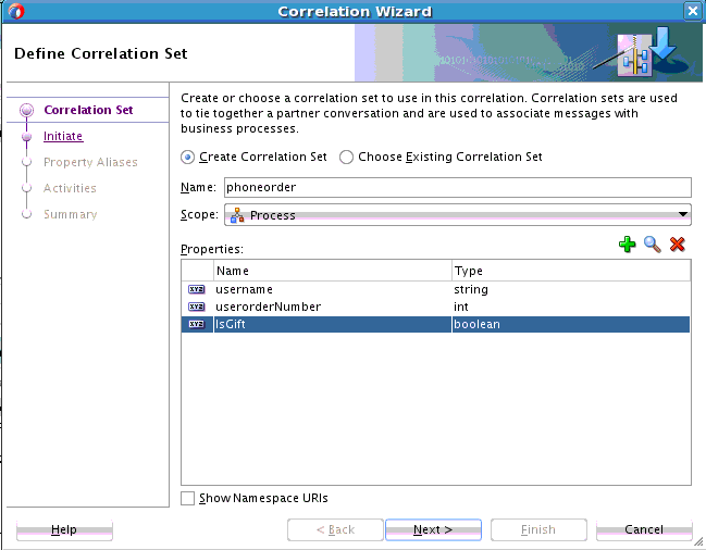
Provide responses appropriate to your environment, then click Next. Table 9-2 provides details.
Table 9-2 Correlation Wizard - Define Correlation Set Page
Field Description Create Correlation Set
Select to create a new correlation set.
Choose Existing Correlation Set
Select an existing correlation set in which to include the selected activity.
Name
Enter the name of the correlation set you want to create.
Scope
Displays the scope or process in which to create the new correlation set.
Properties
-
Click Add to create a new property in the Name column of the Properties table or click Browse to select an existing property.
-
Click the Type column, then click the ellipses to invoke the Type Chooser dialog for selecting the property type (for example, integer, boolean, or some other type).
When complete, the Correlation wizard - Define Correlation Set page looks as shown in Figure 9-2.
Figure 9-2 Correlation Wizard - Define Correlation Set Page
Description of "Figure 9-2 Correlation Wizard - Define Correlation Set Page"The Correlation wizard - Initiate Settings page is displayed.
-
-
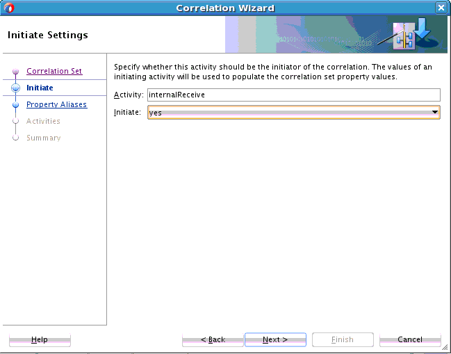
Provide responses appropriate to your environment, then click Next. Table 9-3 provides details.
Table 9-3 Correlation Wizard - Initiate Settings Page
Field Description Activity
Displays the activity on which the correlation is set.
initiate
Select whether this activity is the initiator in the correlation set.
When set to yes, the correlation set is initiated with the values of the properties occurring in the message being sent or received.
When complete, the Correlation wizard - Initiate Settings page looks as shown in Figure 9-3.
Figure 9-3 Correlation Wizard - Initiate Settings Page
Description of "Figure 9-3 Correlation Wizard - Initiate Settings Page"The Correlation wizard - Property Aliases page is displayed for mapping properties to values. The properties defined previously in the Define Correlation Set page of the wizard are displayed in the Property Aliases table.
Property aliases enable you to map a property to a field in a specific message part of a variable. This action enables the property to become an alias for the message part and location.
-
Click a property in the table and select a method for mapping the message part of the variable to the property. Table 9-4 provides details.
-
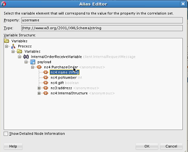
Click the Edit (first) icon to invoke the Alias Editor dialog.
-
Expand the variable.
-
Select the message part to represent the property, and click OK. Figure 9-4 provides details.
-
-
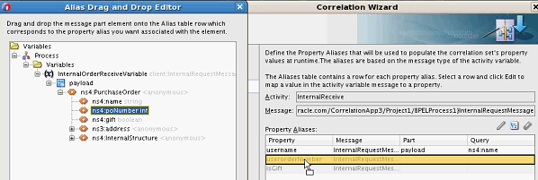
Click the Alias Drag and Drop Editor (second) icon to invoke the Alias Drag and Drop Editor dialog.
-
Expand the variable.
-
Select the message part to represent the property.
-
Drag and drop the message part onto the property row in the Correlation wizard - Property Aliases page. Figure 9-5 provides details.
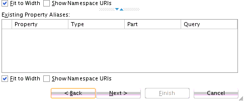
Existing property aliases are listed in the lower part of the Correlation wizard - Property Aliases page, as shown in Figure 9-6. For this example, there are no existing property aliases.
Figure 9-6 Correlation Wizard - Property Aliases Page - Lower Part
Description of "Figure 9-6 Correlation Wizard - Property Aliases Page - Lower Part" -
When complete, click Next.
-
-
Select additional properties to map to specific message parts of variables.
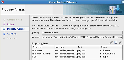
When complete, the Correlation wizard - Property Aliases page looks as shown in Figure 9-7. The properties created in Figure 9-2 are displayed in the Property column. The message elements to which the properties were mapped with either the Alias Editor (Figure 9-4) or Alias Drag and Drop Editor (Figure 9-5) are displayed in the Query column.
Figure 9-7 Correlation Wizard - Property Aliases Page
Description of "Figure 9-7 Correlation Wizard - Property Aliases Page" -
Click Next.
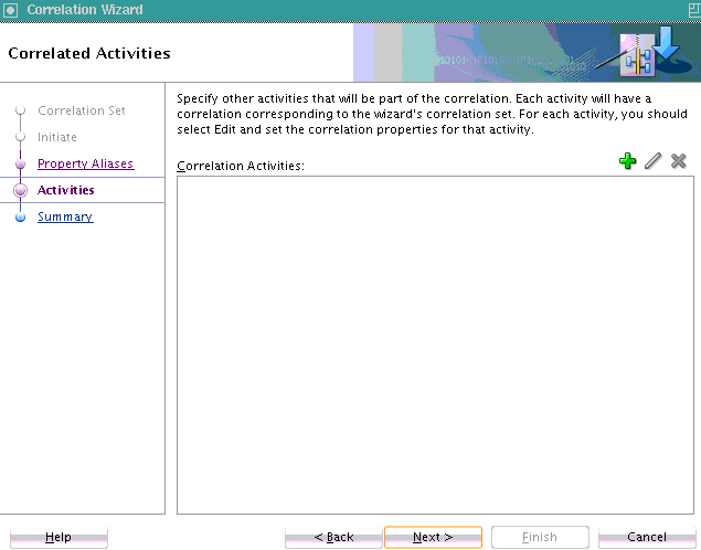
The Correlation wizard - Correlated Activities page is displayed. Figure 9-8 provides details.
Figure 9-8 Correlation Wizard - Property Aliases Page (Without Activity)
Description of "Figure 9-8 Correlation Wizard - Property Aliases Page (Without Activity)" -
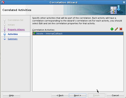
Click the Add icon to add more activities to this correlation set (multiple activities can correlate on the correlation set).
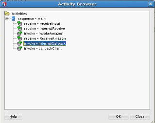
The Activity Browser dialog is displayed.
-
Select the activity to add, and click OK. Figure 9-9 provides details.
Figure 9-9 Activity Browser for Selecting an Activity
Description of "Figure 9-9 Activity Browser for Selecting an Activity"The activity is added to the Correlation Activities field of the Correlation wizard - Correlated Activities page.
-
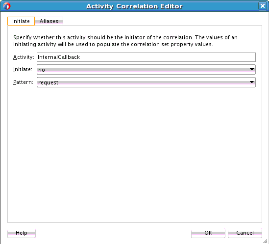
In the Correlation Activities field, select the activity and click Edit to invoke the Initiate tab of the Activity Correlation Editor dialog. Figure 9-10 provides details.
Figure 9-10 Activity Correlation Editor - Initiate Tab
Description of "Figure 9-10 Activity Correlation Editor - Initiate Tab" -
Select appropriate values in the Initiate and Pattern lists. For this example:
-
Select no from the Initiate list (because the correlation set validates the value of the property available in the message).
-
Select request from the Pattern list (because the correlation property is set and validated on the outgoing BPEL message).
For BPEL 2.0, you can select response if the correlation applies to an inbound message, request if the correlation applies to an outbound message, or request-response if the correlation applies to both outbound and inbound messages.
For BPEL 1.1, you can select in if the correlation applies to an inbound message (response), out if the correlation applies to an outbound message (request), or out-in if the correlation applies to both inbound and outbound messages. (response and request).
-
-
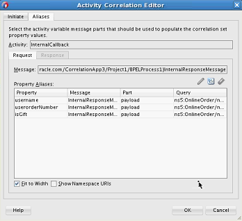
Click the Aliases tab.
-
Repeat Step 4 through Step 7 to select a property and map the message part of the variable to the property.
When complete, the Alias dialog looks similar to that shown in Figure 9-11.
Figure 9-11 Activity Correlation Editor - Alias Tab
Description of "Figure 9-11 Activity Correlation Editor - Alias Tab" -
Click OK to return to the Correlation wizard - Correlated Activities page, which looks as shown in Figure 9-12.
Figure 9-12 Correlation Wizard - Correlated Activities Page (With Selected Activity)
Description of "Figure 9-12 Correlation Wizard - Correlated Activities Page (With Selected Activity)" -
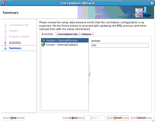
Click Next to review the correlation set details in the Activities, Correlation Set, and Alias tabs.
-
Activities: Displays the activities involved in the correlation and their roles (for example, the receive activity is the initiator and the invoke activity is the responder).
-
Correlation Set: Displays the name of the correlation set.
-
Aliases: Displays the property aliases defined for the activities in the correlation set.
Figure 9-13 provides details.
Figure 9-13 Correlation Wizard - Summary Page
Description of "Figure 9-13 Correlation Wizard - Summary Page" -
-
Click Finish.
The correlation set is created.
-
In the Structure window, view the correlation set, properties, and property aliases you defined in the Correlation wizard.
-
In Oracle BPEL Designer, click the Correlations tab of one of the participating activities to view the details you defined (for example, the receive activity). Figure 9-14 provides details.
Figure 9-14 Correlation Tab of Receive Activity
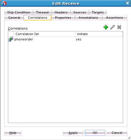
Description of "Figure 9-14 Correlation Tab of Receive Activity" -
If you want to find out which activities are used in a correlation set, perform the following steps.
-
Click the Search icon above Oracle BPEL Designer, and select Correlation Search.
The Correlation Set Chooser dialog is displayed.
-
Select the correlation set, and click OK.
-
In the Correlation Search dialog, click OK.
The activities using the correlation sets are displayed in the Log window.
-
-
If you want to add additional activities to an existing correlation set, right-click the activity, and select Setup Correlation.
The Correlation wizard - Define Correlation Set page is displayed.
-
Select Choose Existing Correlation Set.
-
From the Correlation Sets list, select the correlation set, and click OK.
-
Define the activity by following the pages in the Correlation wizard.
9.2.2 How to Manually Create Correlation Sets From the Correlations Tab
This section describes the steps to manually create correlation sets in an asynchronous service. This example illustrates how to use correlation sets for a process having three receive activities with no associated invoke activities.
9.2.2.2 Step 2: Configuring Partner Links and File Adapter Services
You now create three partner links that use the SOAP service.
This section contains these topics:
-
You create an initial partner link with an adapter service for reading a loan application.
-
You create a second partner link with an adapter service for reading an application response.
-
You create a third partner link with an adapter service for reading a customer response.
9.2.2.2.1 Creating an Initial Partner Link and File Adapter Service
To create an initial partner link and file adapter service:
9.2.2.3 Step 3: Creating Three Receive Activities
You now create three receive activities; one for each partner link. The receive activities specify the partner link from which to receive information.
9.2.2.4 Step 4: Creating Correlation Sets
You now create correlation sets. A set of correlation tokens is a set of properties shared by all messages in the correlated group.
9.2.2.4.1 Creating an Initial Correlation Set
To create an initial correlation set:
- In the Structure window of Oracle JDeveloper, right-click Correlation Sets and select Expand All Child Nodes.
- In the second Correlation Sets folder, right-click and select Create Correlation Set.
- In the Name field of the Create Correlation Set dialog, enter
CorrelationSet1. - In the Properties section, click the Add icon to display the Property Chooser dialog.
- Select Properties, then click the Add icon (first icon at the top) to display the Create Property dialog.
- In the Name field, enter
NameCorr. - To the right of the Type field, click the Browse icon.
- In the Type Chooser dialog, select string and click OK.
- Click OK in each dialog to close the Create Property dialog, the Property Chooser dialog, and the Create Correlation Set dialog.
9.2.2.4.2 Creating a Second Correlation Set
To create a second correlation set:
- Return to the Correlation Sets section in the Structure window of Oracle JDeveloper.
- Right-click the Correlation Sets folder and select Create Correlation Set.
- In the Name field of the Create Correlation Set dialog, enter
CorrelationSet2. - In the Properties section, click the Add icon to display the Property Chooser dialog.
- Select Properties, then click the Add icon to display the Create Property dialog.
- In the Name field, enter
IDCorr. - To the right of the Type field, click the Browse icon.
- In the Type Chooser dialog, select double and click OK.
- Click OK in each dialog to close the Create Property dialog, the Property Chooser dialog, and the Create Correlation Set dialog.
9.2.2.5 Step 5: Associating Correlation Sets with Receive Activities
You now associate the correlation sets with the receive activities. You perform the following correlation set tasks:
-
For the first correlated group, the first and second receive activities are correlated with the CorrelationSet1 correlation set.
-
For the second correlated group, the second and third receive activities are correlated with the CorrelationSet2 correlation set.
9.2.2.5.1 Associating the First Correlation Set with a Receive Activity
To associate the first correlation set with a receive activity:
- Double-click the receiveFirst receive activity to display the Receive dialog.
- Click the Correlations tab.
- Click the Add icon to display the correlation set dropdown list.
- Select CorrelationSet1.
- Click the Initiate column to display a dropdown list, and select yes. When set to yes, the set is initiated with the values of the properties occurring in the message being exchanged.
- Click OK.
9.2.2.5.2 Associating the Second Correlation Set with a Receive Activity
To associate the second correlation set with a receive activity:
9.2.2.6 Step 6: Creating Property Aliases
Property aliases enable you to map a global property to a field in a specific message part. This action enables the property name to become an alias for the message part and location. The alias can be used in XPath expressions.
9.2.2.6.1 Creating Property Aliases for NameCorr
You create the following two property aliases for the NameCorr correlation set:
-
Map NameCorr to the LoanAppl message type part of the receiveFirst receive activity. This receive activity is associated with the FirstReceive partner link (defined by the FirstReceive.wsdl file).
-
Map NameCorr to the incoming LoanAppResponse message type part of the receiveSecond receive activity. This receive activity is associated with the SecondReceive partner link (defined by the SecondFileRead.wsdl file).
To create property aliases for NameCorr:
9.2.2.6.2 Creating Property Aliases for IDCorr
You create the following two property aliases for the IDCorr correlation set:
-
Map IDCorr to the LoanAppResponse message type part of the receiveSecond receive activity. This receive activity is associated with the SecondReceive partner link (defined by the SecondFileRead.wsdl file).
-
Map IDCorr to the CustResponse message type part of the receiveThird receive activity. This receive activity is associated with the ThirdReceive partner link (defined by the ThirdFileRead.wsdl file).
To create property aliases for IDCorr:
9.2.3 What You May Need to Know About Conversion IDs and Different Composite Revisions
Do not use the same conversion ID for different revisions of a SOA composite application. When correlation sets are used in a BPEL process, you have explicit control over the conversation ID value. Oracle SOA Suite does not interfere or add restrictions on conversation ID value generation. This situation means that even though it appears that Oracle SOA Suite is generating the same conversation ID for different revisions, you actually control this behavior. Oracle SOA Suite does not restrict you from using the same conversation ID for different instances of different revisions.
If you do not use correlation sets, the conversation ID generated is unique and this is not a problem because Oracle SOA Suite decides which conversation ID to generate, and not you.
Oracle SOA Suite does not execute a revision check for callback routing. Routing of callback messages is only based on the following:
-
Conversation ID: This is calculated based on the input value and correlation set. If you use the same correlation set for two revisions of processes and enter the same input when creating an instance, both revisions subscribe using the same conversation ID. This causes confusion when a callback for one revision is delivered to another revision.
-
Operation name (is the same for both revisions).
-
BPEL service component name (is also the same for both revisions).
The concept of a revision number is applicable to Oracle SOA composite applications, and is not part of the BPEL specification. This is why it is not used as part of the routing decision.
There is another complication in which adding a revision as part of callback routing causes problems. When sending a callback, you also specify the endpoint URL. If the endpoint URL does not contain the composite revision (which is extremely likely), the message is assumed to be routed to the default revision. If Oracle SOA Suite runtime adds a revision check as part of callback routing, the callback for the nondefault revision instance is never possible.
For example, assume you have the following BPEL process:
-
An entry receive activity named receive_1 (on which a correlation set is used)
-
An invoke activity, which invokes a web service
-
A receive activity named receive_2
Assume you perform the following steps:
-
Deploy revision 1.0 of composite_A, which includes a BPEL component.
-
Create an instance of revision 1.0, which is using a correlation set, and input a value of
123, which generatesconv_id = "123".This process now invokes a web service through a one-way invoke activity and then waits on the receive_2 activity for a callback to arrive.
-
Deploy revision 2.0 of composite_A, which now becomes the default revision.
A web service sends a callback for the instance for revision 1.0. However, as a part of its URL, it does not specify the revision number. You typically create a callback so that the URL does not use the revision number. This is because web services are external and you cannot change web service settings to continue using a revision tag because it is internal to Oracle SOA Suite and is a concept that the external world does not understand.
Since a revision number is not specified, the SOA server assumes that the revision number must be 2.0 and, if the routing of the callback takes the revision number into account, it cannot forward this callback intended for 1.0 to the correct revision 1.0. Instead, it attempts to route it to the default revision of 2.0, which does not have any instance waiting for the callback.
You cannot route callback messages based on revisions. You only receive the option to route callback messages based on the conversion ID (if the correlation set is not used, then even this is not under your control), operation name, and component name.
For these reasons, different instances must use different conversation IDs (which means different input is used for creating a conversion ID) to avoid confusion, and routing should be solely based on a conversation ID.
9.2.4 What You May Need to Know About Setting Correlations for an IMA Using a fromParts Element With Multiple Parts
Assume you have the following scenario:
-
A BPEL 2.0 process with a WSDL message type that has multiple parts that are identical in type.
-
A property alias has been defined based on the element type of the above part.
For a process that has an inbound message activity (IMA) (for example, a receive activity, onMessage branch of a scope or pick activity, or onEvent branch of a scope activity in BPEL 2.0) that uses the fromParts element with fromParts defined for each part, correlations cannot be defined because the runtime environment cannot determine the part to which to apply the property alias.
For more information about mapping WSDL message parts with the toParts and fromParts elements, see Mapping WSDL Message Parts in BPEL 2.0.
9.3 Routing Messages to the Same Instance
Oracle BPEL Process Manager supports a message aggregation feature. When multiple messages are routed to the same process/partner link/operation name, the first message is routed to create a new instance and subsequent messages can be routed to continue the created instance using a midprocess receive activity.
Message aggregation enables you to use the same operation (or event name) in an entry receive activity and a midprocess receive activity.
Note:
-
This feature only performs aggregation, and not resequencing. This feature does not resequence messages arriving out of order into an ordered format. Therefore, the first message only means the first message processed. This may be different from the first message in a time sequence order.
-
You must use correlation sets to take advantage of the message aggregation feature.
-
Synchronous operations as ambiguous calls (at both beginning and midprocess receive activities) are supported. However, this is not a recommended use of this feature and should be avoided.
9.3.1 How to Configure BPEL Process Instance Creation
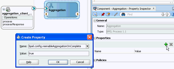
You can control the number of instances to create and use to route messages with the reenableAggregationOnComplete property.
To configure BPEL process instance creation:
9.3.2 How to Use the Same Operation in Entry and Midprocess Receive Activities
Assume you create a correlation set as shown in the example that follows. All messages to Oracle BPEL Process Manager are routed to the same operation name. The messages have the same correlation ID. The interface WSDL does not differentiate between the entry activity (receiveInput) and the midprocess receive activity (Continue_Receive). All messages are processed using the initiate operation. A single instance is created to which to route all messages.
This differs from releases before 11g Release 1 11.1.1.6, in which you needed to define different operation names on the same partner link. The process had to expose two operations and the caller had to choose the correct operation name.
<receive name="receiveInput" partnerLink="client" portType="client:BPELProcess1"
 operation="initiate" variable="inputVariable" createInstance="yes">
 <correlations>
  <correlation initiate="yes" set="CorrelationSet_1"/>
 </correlations>
</receive>

<!-- Asynchronous callback to the requester. (Note: the callback location and
 correlation id is transparently handled using WS-addressing.) -->
<assign name="Assign_1">
 <copy>
  <from variable="inputVariable" part="payload"
 query="/client:BPELProcess1ProcessRequest/client:input"/>
  <to variable="Invoke_1_initiate_InputVariable" part="payload"
 query="/ns1:BPELProcess2ProcessRequest/ns1:input"/>
 </copy>
</assign>

<receive name="Continue_Receive" partnerLink="client"
 portType="client:BPELProcess1" operation="initiate" variable="inputVariable"
 createInstance="no">
 <correlations>
  <correlation initiate="no" set="CorrelationSet_1"/>
 </correlations>
</receive>
For event delivery network (EDN) business events, you substitute the operation attribute with bpelx:eventName in both the entry and midprocess receive activities.
bpelx:eventName="ns3:initiateEvent"/>
Information is maintained in the DLV_AGGREGATION table:
-
Conversation ID
-
Domain name
-
Component name and type
-
Composite name, label, and revision
-
State
-
Received date
-
CI key
-
Primary key
This information can be deleted from this table with the purge scripts or from the Auto Purge page in Oracle Enterprise Manager Fusion Middleware Control. For more information about both of these options, see the Administering Oracle SOA Suite and Oracle Business Process Management Suite.
9.3.3 How to Route a Message to a New or Existing Instance when Using Correlation Sets
For a BPEL process using correlation sets, the correct routing is performed. The message can be either of the following:
-
An invoke message creating a new instance
-
A callback message continuing an existing instance
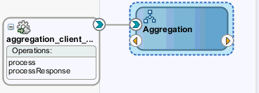
Figure 9-19 shows entry and midprocess receive activities using the same operation (process).
Figure 9-19 Routing a New Message to a New or Existing Instance
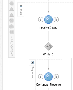
Description of "Figure 9-19 Routing a New Message to a New or Existing Instance"
The following provides an example of the entry and midprocess receive activities using the same operation (process).
<receive name="receiveInput" partnerLink="client" portType="client:BPELProcess1"
 operation="process" variable="inputVariable" createInstance="yes">
 <correlations>
  <correlation initiate="yes" set="CorrelationSet_1"/>
 </correlations>
</receive>

<!-- some business logic -->

<while name="While_1" condition=*loop for 3 iterations*>
 <sequence name="Sequence_1">
  <receive name="Continue_Receive" partnerLink="client"
 portType="client:BPELProcess1" operation="process" variable="inputVariable"
 createInstance="no">
   <correlations>
    <correlation initiate="no" set="CorrelationSet_1"/>
   </correlations>
  </receive>

<!-- some business logic -->

 </sequence>
</while>
In the initial scenario in the preceding example, the following actions occur in BPEL process P1:
-
A partner provides four messages (message 1, message 2, message 3, and message 4) for the same partner (correlation ID
101). -
Message 1 creates a new instance of BPEL process P1. This message is marked as an invoke message.
-
Messages 2, 3, and 4 are received using the
Continue_Receiveactivity. These messages are marked as callback messages. -
The instance closes because three iterations of the
whileloop are expected.
Assume now that additional messages are routed, which can potentially cause race conditions to occur. Table 9-13 provides details.
Table 9-13 Message Delivery Scenarios
| Scenario | Description | Marked as Invoke Message | Marked as Callback Message |
|---|---|---|---|
|
1 |
Assume the partner now provides message 5 for the same correlation ID ( |
|
|
|
2 |
If messages 4 and 5 are received within a small time window, it is possible that message 4 is closing the instance BPEL process P1 and message 5 is routed as a callback to that instance. This scenario can cause a race condition. For example:
|
|
|
|
3 |
This is similar to scenario 2. However, in this case, messages 7, 8, and 9 are not received. For example:
There are several options for message recovery.
|
|
|
