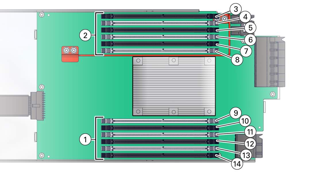
DIMM Physical Layout and Numbering
Each CMOD contains 12 DIMM slots arranged in two groups of six slots. Each group of slots is controlled by one of the four memory buffers. Each buffer has two independent memory channels, Ch A and Ch B (six memory channels per CMOD). Each channel supports 1-6 DIMMs and has six assigned DIMM slots.
Channels 0, 1, and 2 are located on one side of the processor, and channels 3, 4 and 5 are on the other side of the processor. To differentiate the two memory channels within a group of slots, the six DIMM slots assigned to each channel have color-coded black slots with black levers, or white slots with white levers.
The following illustration shows the location of the memory buffers, the groups of DIMM slots, and the slots assigned to each channel.

| Call Out | Description |
|---|---|
|
1 |
DIMM Banks A, B, C |
|
2 |
DIMM Banks D, E, F |
|
3 |
Channel F, Slot 0, DIMM 0 |
|
4 |
Channel F, Slot 1, DIMM 1 |
|
5 |
Channel E, Slot 0, DIMM 2 |
|
6 |
Channel E, Slot 1, DIMM 3 |
|
7 |
Channel D, Slot 0, DIMM 4 |
|
8 |
Channel D, Slot 1, DIMM 5 |
|
9 |
Channel A, Slot 0, DIMM 6 |
|
10 |
Channel A, Slot 1, DIMM 7 |
|
11 |
Channel B, Slot 0, DIMM 8 |
|
12 |
Channel B, Slot 1, DIMM 9 |
|
13 |
Channel C, Slot 0, DIMM 10 |
|
14 |
Channel C, Slot 1, DIMM 11 |