- Oracle Exadata Database Server X8-8 Service Manual
- Servicing Components
- Servicing CPU Module (CMOD) Components (FRU)
- Servicing Processors (FRU)
- Install a Processor
Install a Processor
Caution:
Do not touch the processor socket pins. The processor socket pins are very fragile. A light touch can bend the processor socket pins beyond repair.- Attach an antistatic wrist strap to your wrist, and then to a metal area on the chassis.
-
Ensure that the replacement processor is identical to the failed
processor that you removed.
For a description of the processors that are supported by the server, see Product Description.
-
Prepare the new processor for installation.
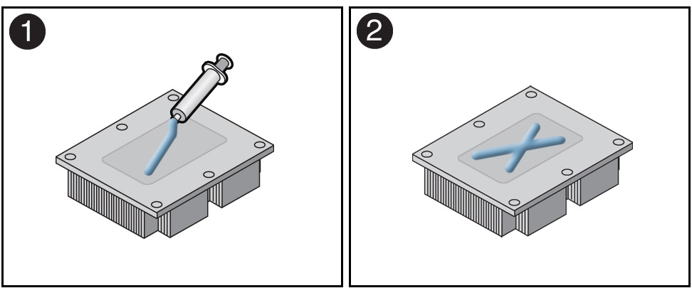
Use the syringe supplied with the new or replacement processor [1] to apply 0.3 cc of thermal interface material (TIM) in an "X" pattern to the processor contact area of the heatsink [2].
Note:
Do not distribute the TIM; the pressure of the heatsink will do so for you when you install the heatsink. -
Install the new processor.
-
Align the pin 1 indicators between the heatsink and processor
carrier in the packaging tray, and place the heatsink (thermal
side down) onto the processor carrier until it snaps in place
and lies flat.
Note:
The processor carrier has latching posts at each corner: two that insert into heatsink holes and two that attach to the edge of the heatsink.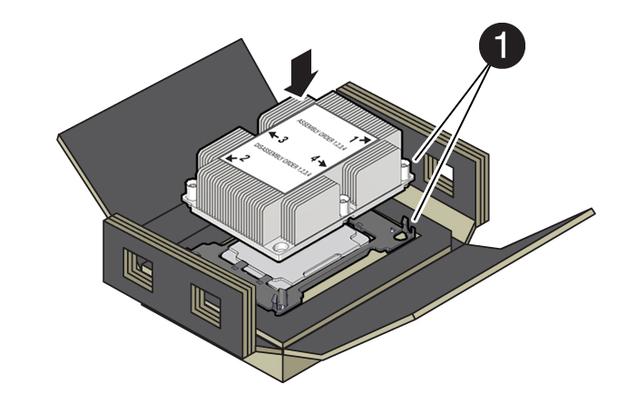
Callout Description 1
Pin 1 indicator
-
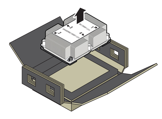
Lift the processor-heatsink module out of the packaging
tray.
-
Align the processor-heatsink module to the processor socket
bolster plate on the motherboard, matching the pin 1 location (a
triangle indicator).
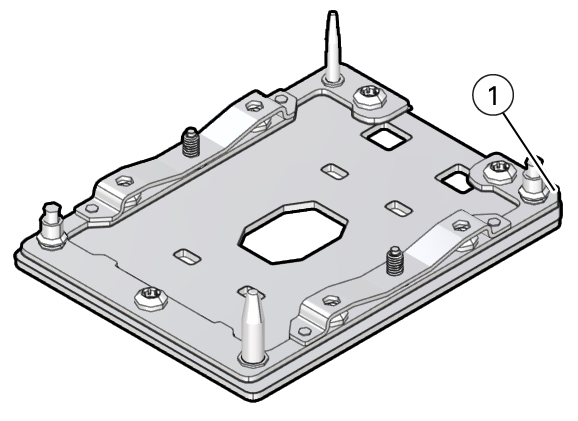
Callout Description 1
Pin 1 indicator
-
Place the processor-heatsink module on the socket on the
motherboard.
The socket bolster plate has alignment pins that go into holes on the processor-heatsink module to help center the module during installation.
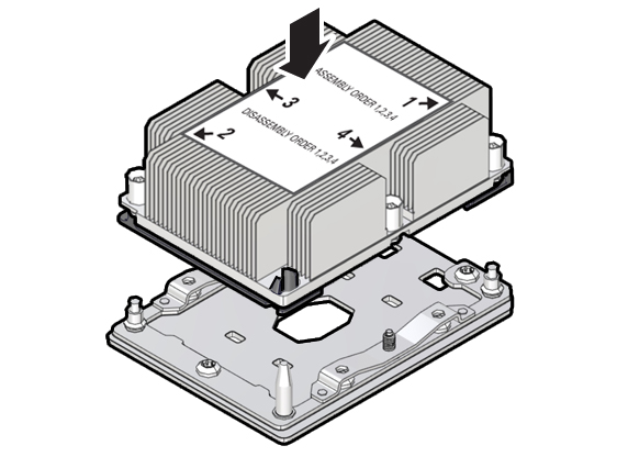
-
Ensure that the processor-heatsink module lies evenly on the
bolster plate and that the captive screws align with the
threaded socket posts [1].
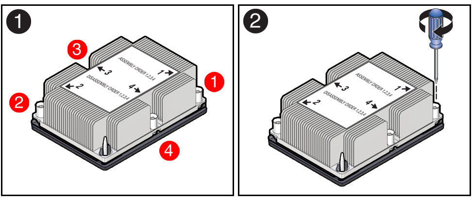
-
Using a 12.0 in-lbs (inch-pounds) torque driver with a Torx
T30 bit, tighten the processor-heatsink module to the socket.
First, fully tighten captive nuts 1 and 2. Then fully tighten
nuts 3 and 4 [2].
As you tighten nuts 3 and 4, some resistance occurs as the bolster leaf spring rises and comes in contact with the heatsink.
-
Align the pin 1 indicators between the heatsink and processor
carrier in the packaging tray, and place the heatsink (thermal
side down) onto the processor carrier until it snaps in place
and lies flat.
- Install the CMOD cover.
-
Install the CMOD.
See Install a CMOD.
-
Return the server to operation.
Return the server to service after performing warm or cold service.
-
Reconnect the power cords to the AC inlets after performing
cold service.
Verify that the four power supply AC OK LEDs are lit.
-
Power on the main server power.
See Power On the Server.
-
Reconnect the power cords to the AC inlets after performing
cold service.
-
Use Oracle ILOM to clear server processor faults.
Refer to the Oracle Integrated Lights Out Manager (ILOM) 4.0 Documentation Library at Systems Management and Diagnostics Documentation for more information about the following steps.
-
To show server faults, log in to the server as
root using the Oracle ILOM CLI, and type
the following command to list all known faults on the server:
show command
-> show /SP/faultmgmt
The server lists all known faults, for example:
-> show /SP/faultmgmt Targets: shell 0 (/SYS/MB/P0) Properties: Commands: cd show -
To clear the fault identified in Step 6.a, type the following command:
set command
-> set /SYS/MB/P0 clear_fault_action=true
For example:
-> set /SYS/MB/P0 clear_fault_action=true
Are you sure you want to clear /SYS/MB/P0 (y/n)? y
Set ‘clear_fault_action’ to ‘true’
Alternatively, to clear all known faults in the server, log into the Oracle Solaris OS and issue the
fmadm repaircommand, or log into the Oracle ILOM service processor from the Oracle ILOM Fault Management Shell and issue thefmadm repaircommand. For more information about how to use the Oracle ILOM Fault Management Shell and supported commands, see the Oracle ILOM User's Guide for System Monitoring and Diagnostics Firmware Release 4.0.x in the Oracle Integrated Lights Out Manager (ILOM) 4.0 Documentation Library at Systems Management and Diagnostics Documentation.
-
To show server faults, log in to the server as
root using the Oracle ILOM CLI, and type
the following command to list all known faults on the server:
show command