Back Panel Features
This section describes the server back panel features.
The components on the back panel are divided between System A and System B. System A is associated with SMOD0. System B is associated with SMOD1.
-
In single 4-socket systems, System A is active and System B is inactive.
-
In dual 4-socket systems, System A and System B are active and act as independent servers.
-
In single 8-sockets, System A and System B are active and merged into a single server, although some redundant features in SMOD1 are nonfunctional.
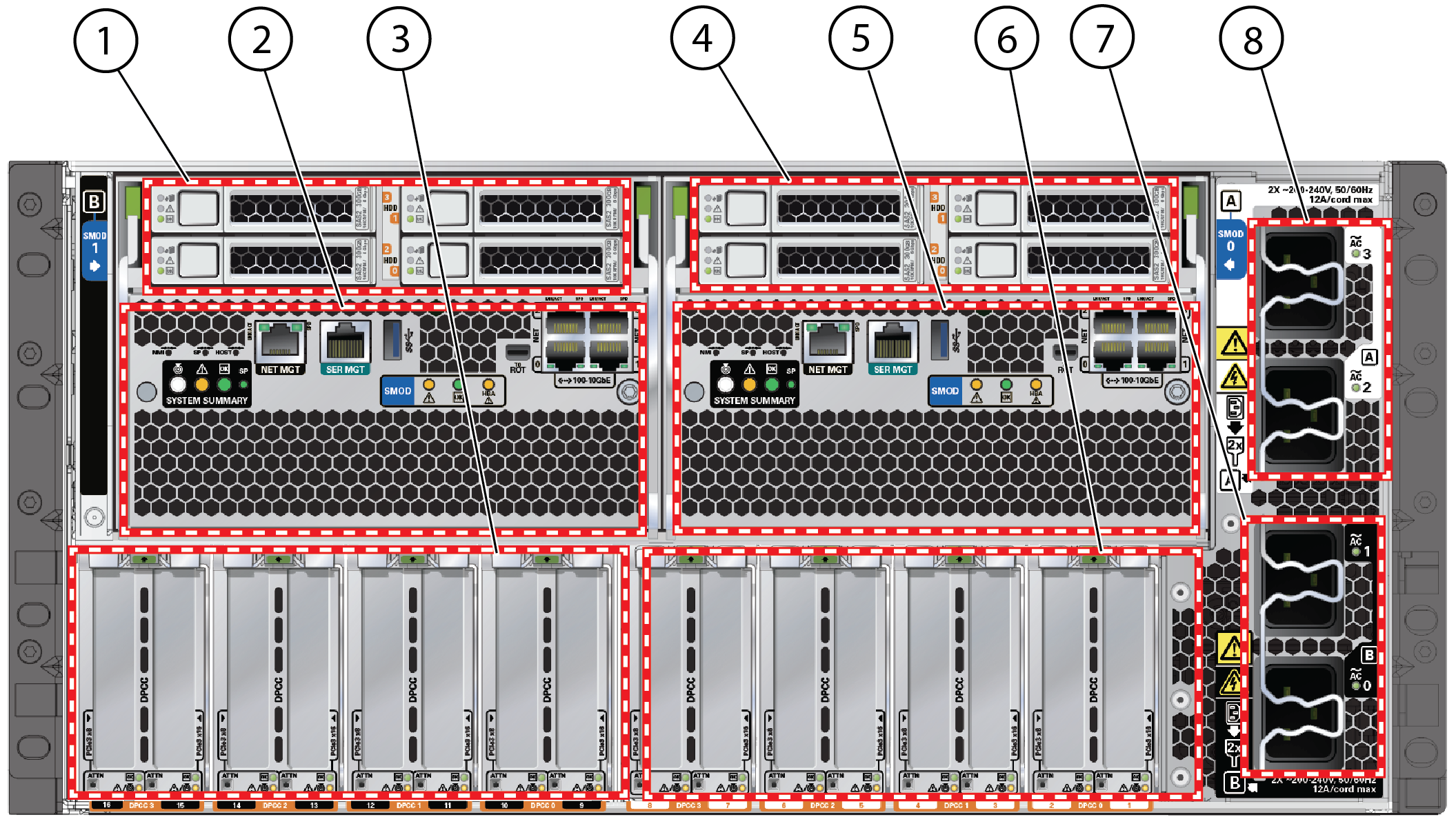
The following figure shows the Oracle Server X8-8 back panel and the location of status indicators (LEDs), connectors, and PCIe slots.
For information on how to interpret the status indicators (LEDs), refer to the Troubleshooting and Diagnostics in Oracle Server X8-8 Service Manual.

| Callout | Assignment | Description |
|---|---|---|
|
1 |
System B |
HDD/SSD bays: See Storage Drive Controls and Indicators.
|
|
2 |
System B |
SMOD1: See SMOD Status Indicators and Buttons. |
|
3 |
System B |
PCIe card slots 9 through 16: See PCIe Cards.
|
|
4 |
System A |
HDD/SSD bays 0 through 3: See Storage Drive Controls and Indicators.
|
|
5 |
System A |
SMOD0: See SMOD Status Indicators and Buttons. |
|
6 |
System A |
PCIe card slots 1 through 8: See PCIe Cards.
|
|
7 |
System A |
AC power inlets 2 and 3: See Power Supply Controls and Indicators. |
|
8 |
System B |
AC power inlets 0 and 1: See Power Supply Controls and Indicators. |