Front Panel Features
This section describes the server front panel features.
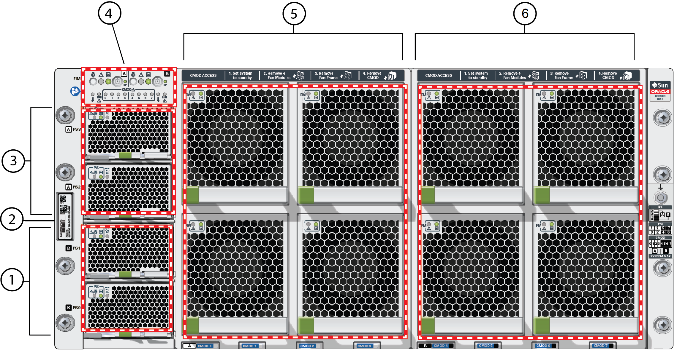
The following figure shows the status indicators (LEDs), connectors, and drives located on the server front panel.

| Callout | Assignment | Description |
|---|---|---|
|
1 |
System B |
Power supplies 0 and 1: See Power Supply Controls and Indicators. |
|
2 |
System A and System B |
Product Serial Number (PSN) label and Radio Frequency Identification (RFID) tag: See . |
|
3 |
System A |
Power supplies 2 and 3: See Power Supply Controls and Indicators. |
|
4 |
System A and System B |
Front indicator module (FIM): See Front Indicator Module. |
|
5 |
System A |
Fan modules 0, 1, 2, and 3: See Fan Module Controls and Indicators. |
|
6 |
System B |
Fan modules 3, 4, 5, and 6: See Fan Module Controls and Indicators. |
Note:
All System B components are inactive in single 4-socket systems except for the fans.