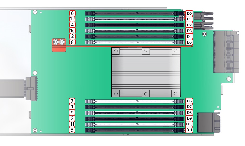
DIMM Slot Population Order
The DIMM slot population order is as follows:
Note:
Always populate the DIMM slot furthest from the memory buffer first.
-
Installation Order DIMM: 1 D7, 2 D4, 3 D9, 4 D2, 5 D11, 6 D0, 7 D6, 8 D5, 9 D8, 10 D3, 11 D10, 12 D1
-
Populate the slots with black slots and black levers: D0 D3 D6 D9 D12 D15 D18 D21
The slot population for the minimum DIMM configuration is D0/D6/D12/D18 per CMOD
-
Populate the white slot, white lever slots: D2 D5 D8 D11 D14 D17 D20 D23
The following table describes the proper order in which to populate DIMMs in a CMOD using the numbered callouts in the above figure, and the DIMM socket labels (D0 through D11).
Table 4-1 DIMM Population Order for CMODs
| Population Order | DIMMs Sockets for Processor 0 (P0) |
|---|---|
|
Fill the black sockets first |
- |
|
1 |
D7 |
|
2 |
D4 |
|
3 |
D9 |
|
4 |
D2 |
|
5 |
D11 |
|
6 |
D0 |
|
Then fill the white sockets |
- |
|
7 |
D6 |
|
8 |
D5 |
|
9 |
D8 |
|
10 |
D3 |
|
11 |
D10 |
|
12 |
D1 |
The physical layout of the CMOD memory DIMMs and DIMM installation order is shown in the following figure.

For component serviceability, locations, and designations, see Replaceable Components.