- Oracle Server X8-8 Service Manual
- Servicing Components
- Servicing CPU Module (CMOD) Components (FRU)
- Upgrade the Server From Four to Eight CMODs (FRU)
Upgrade the Server From Four to Eight CMODs (FRU)
Perform this procedure to add CMODs to System B.
If you have a server configured with four CMODs, you can expand the server's processing capabilities by upgrading the server configuration to eight CMODs. Obtain the Four CPU Module Package. The package contains the components required to upgrade the server. Contact your sales representative for information about ordering the CPU module packages.
For component serviceability, locations, and designations, see Replaceable Components.
Caution:
CMODs should be removed and replaced only by authorized Oracle Service personnel.
-
Prepare the server for warm service.
See Preparing the Server for Component Replacement.
Note:
This procedure can also be completed as a cold service procedure.
-
Remove all eight fan modules.
See Remove a Fan Module.
-
Remove both fan frames.
See Remove a Fan Frame.
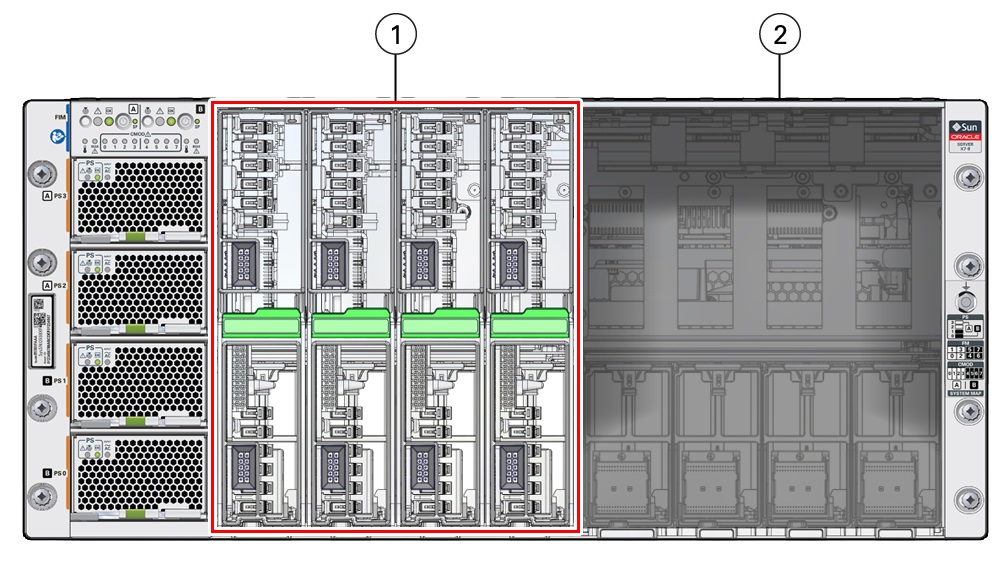
In a four-CMOD configuration, the four CMOD slots on the right side of the server are vacant.

Call Out Description 1
Four CMODs installed in left bay (System A)
2
Empty right-side bay (System B)
-
Open each new CMOD and ensure that the DIMMs are configured correctly and
properly seated in their slots.
Caution:
These procedures require that you handle components that are sensitive to electrostatic discharge. This sensitivity can cause the components to fail. To avoid damage, ensure that you follow antistatic practices as described in Electrostatic Discharge and Static Prevention Measures.
-
Remove the CMOD cover.
To remove the CMOD cover, press down on the green release button and slide the cover away from the front of the CMOD.
-
Ensure that all DIMMs are installed in their slots.
Ensure that that all DIMM levers are in the fully upright and locked position.
-
Ensure that the processor configuration matches the installed
CMODs.
For processor configuration information, see Product Description.
-
Ensure that the DIMM configuration matches the installed
CMODs.
For DIMM configuration information, see DIMM Population Rules.
-
Replace the CMOD cover.
Lower the cover onto the CMOD. To install the CMOD cover, align the standoffs on the inside of the cover with the slots in the CMOD chassis. This position leaves a gap between the lead edge of the cover and the front edge of the CMOD.
Slide the cover toward the front of the CMOD until it locks in place.
-
Remove the CMOD cover.
-
To upgrade the server, do the following:
-
Install a CMOD in the first vacant slot at the farthest left
position.
See Install a CMOD.
- Repeat the above step for the remaining three slots.
-
Install a CMOD in the first vacant slot at the farthest left
position.
-
Install both fan frames.
See Install a Fan Frame.
-
Install all eight fan modules.
See Install a Fan Module.
- Prepare the server for operation.
- Configure the new CMODs.