Identify and Remove a Processor

Caution:

Whenever you remove a processor, replace it with another processor and reinstall the processor heatsink; otherwise, the server might overheat due to improper airflow. See Install a Processor.
  • Use an antistatic wrist strap and a work space with an antistatic mat.

    See Electrostatic Discharge Safety.

  • Use ESD gloves, if possible, when handling the processor (not latex or vinyl).

  • Be careful not to touch the processor socket pins.

    Caution:

    The processor socket pins are very fragile. A light touch can bend the processor socket pins beyond repair.
  • Obtain a medium flat blade screwdriver

  • Obtain a T30 Torx driver or bit

  1. Prepare the server for service.
    1. Power off the server and disconnect the power cords from the power supplies.
    2. Attach an antistatic wrist strap to your wrist, and then to a metal area on the chassis.
    3. Extend the server to the maintenance position.
    4. Remove the server top cover.
    5. Remove the air baffle.
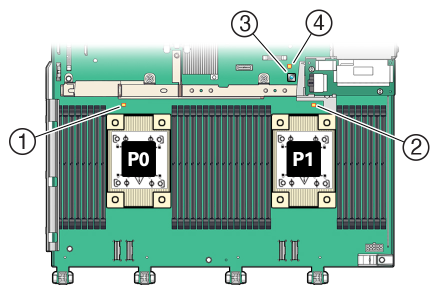
  2. Identify the location of the failed processor by pressing the Fault Remind button on the motherboard I/O card.

    Note:

    When you press the Fault Remind button, an LED located next to the Fault Remind button lights green, indicates that there is sufficient voltage in the fault remind circuit to light any fault LEDs that were lit due to a failure. If this LED fails to light when you press the Fault Remind button, it is likely that the capacitor powering the fault remind circuit lost its charge. This can happen if you press the Fault Remind button for a long time with fault LEDs lit, or if power was removed from the server for more than 15 minutes.

    The processor fault LED for the failed processor lights. The processor fault LEDs are located next to the processors. See Motherboard Status Indicators.

    • If the processor fault LED is off, the processor is operating properly.

    • If the processor fault LED is on (amber), the processor is has failed and must be replaced.


    Figure showing how to identify a failed processor by pressing the Fault Remind button.
    Callout Description

    1

    Processor 0 fault LED

    2

    Processor 1 fault LED

    3

    Fault Remind button

    4

    Fault Remind Circuit Good LED

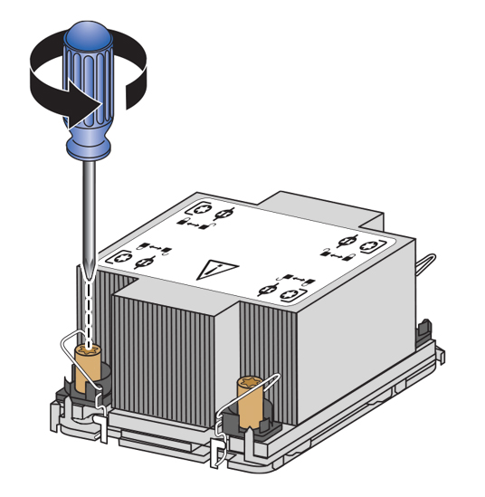
  3. Using a Torx T30 screwdriver, loosen the four captive load nuts that secure the processor-heatsink module to the socket. The nuts can be loosened in any order.

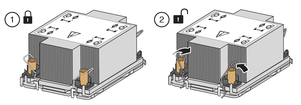
    Do not attempt to remove the processor-heatsink with the anti-tilt wires locked.


    Figure showing the captive load nuts being loosened on the processor-heatsink module.
  4. Pivot the anti-tilt wire around each of the four captive heatsink load nuts to the unlocked position.

    Leave the anti-tilt wires in the unlocked position until installation.


    Figure showing the processor-heatsink module anti-tilt wires being set to the unlocked position.
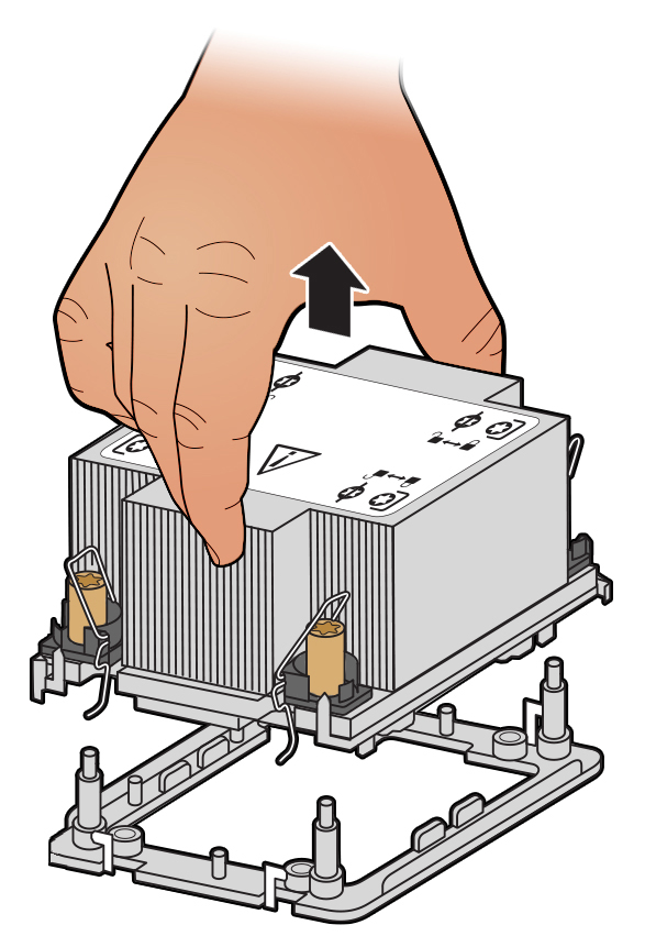
  5. Then, lift the processor-heatsink module straight up from the socket.

    Note:

    Always hold the processor-heatsink module along the axis of the fins to prevent damage.

    Figure showing processor-heatsink module being removed from the socket.
  6. Separate the processor from the heatsink.
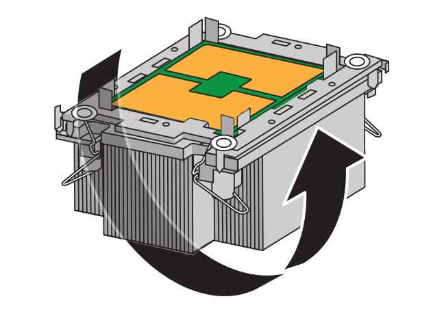
    1. Flip over the processor-heatsink module, place it on a flat surface and locate the thermal interface material (TIM) breaker slot.

      Figure showing the processor-heatsink module being flipped over.
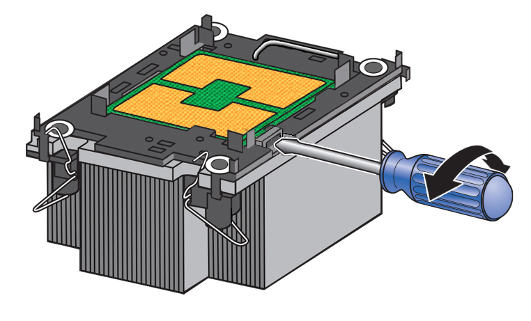
    2. While holding down the heatsink by its edges, insert a flat blade screwdriver into the TIM breaker slot. Using a rocking motion, gently pry the corner of the processor carrier away from the heatsink.

      Note:

      The blade of the screwdriver should go into the slot between the heatsink and processor carrier, not the processor and processor carrier.

      Figure showing how to use a screwdriver to break the TIM adhesive between the processor carrier and the heatsink.

      Caution:

      There is a thin layer of thermal grease between the heatsink and the processor. Do not allow the thermal grease to contaminate the work space or other components.
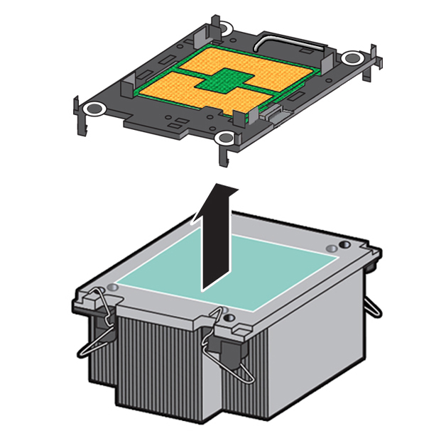
    3. Remove the processor carrier (with processor still attached) from the heatsink. The carrier has plastic latch tabs that attach it to the heatsink, pry or pinch the tabs as appropriate to detach the carrier from the heatsink.

      Figure showing the processor carrier being removed from the heatsink.
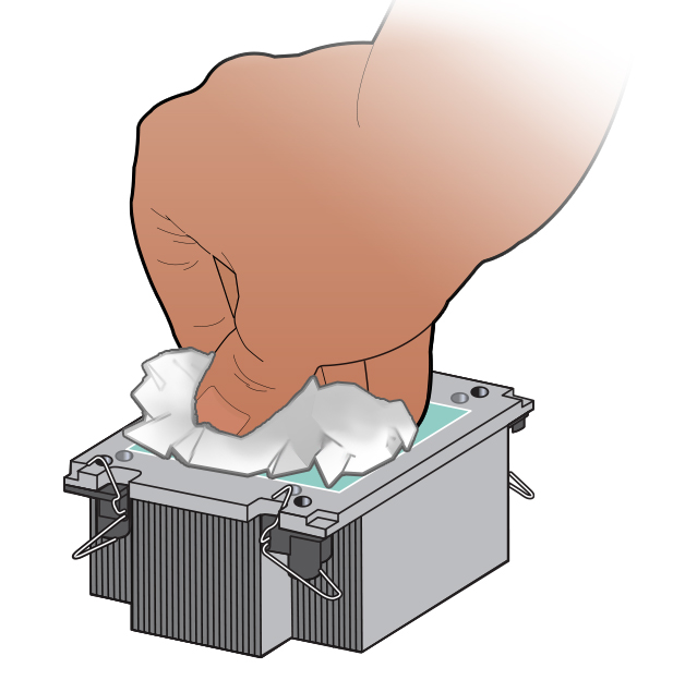
  7. If you plan on reusing either the heatsink or processor, clean off the thermal interface material (TIM) using the supplied alcohol wipes. If reusing a processor, do not remove it from the processor carrier.

    Figure showing TIM being cleaned off a heatsink.

    Caution:

    Failure to clean thermal grease from the heatsink could result in the accidental contamination of the processor socket or other components. Also, be careful not to get the grease on your fingers, as this could result in contamination of components.

Related Topic: