Cell Maps
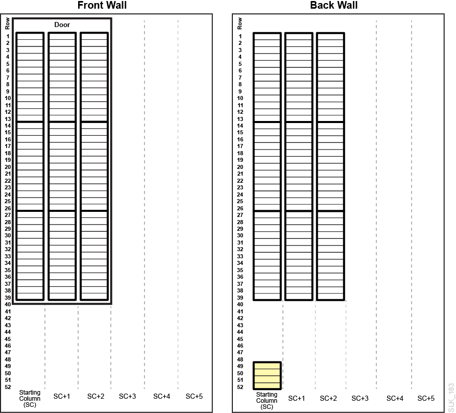
Each module in the library has a particular layout for the drive bays and storage slots.
Legend
| Cell | Description |
|---|---|
|
|
Normal data storage cell |
|
|
CAP cell |
|
|
Unavailable with no module to left |
|
|
Unavailable with no module to right |
|
|
Unavailable in a Parking Module |
|
|
Module identification block (see Module Identification Block) |
|
|
System cell for cleaning and diagnostic tapes |
Figure 8-1 Base Module - Front Wall and Back Wall with 8 Drives
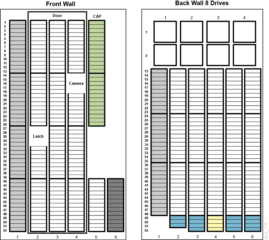
Figure 8-2 Base Module- Back Wall 16 Drives and 24 Drives
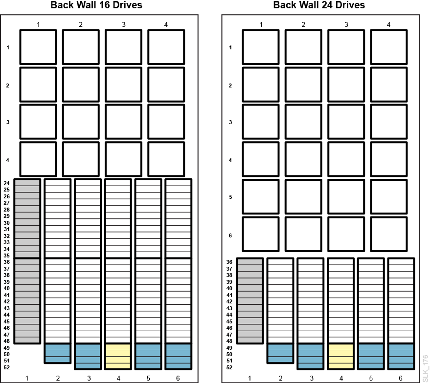
Figure 8-3 Drive Module - Front Wall
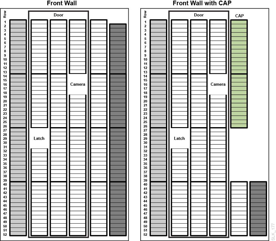
Figure 8-4 Drive Module - Back Wall 8 Drives and 16 Drives
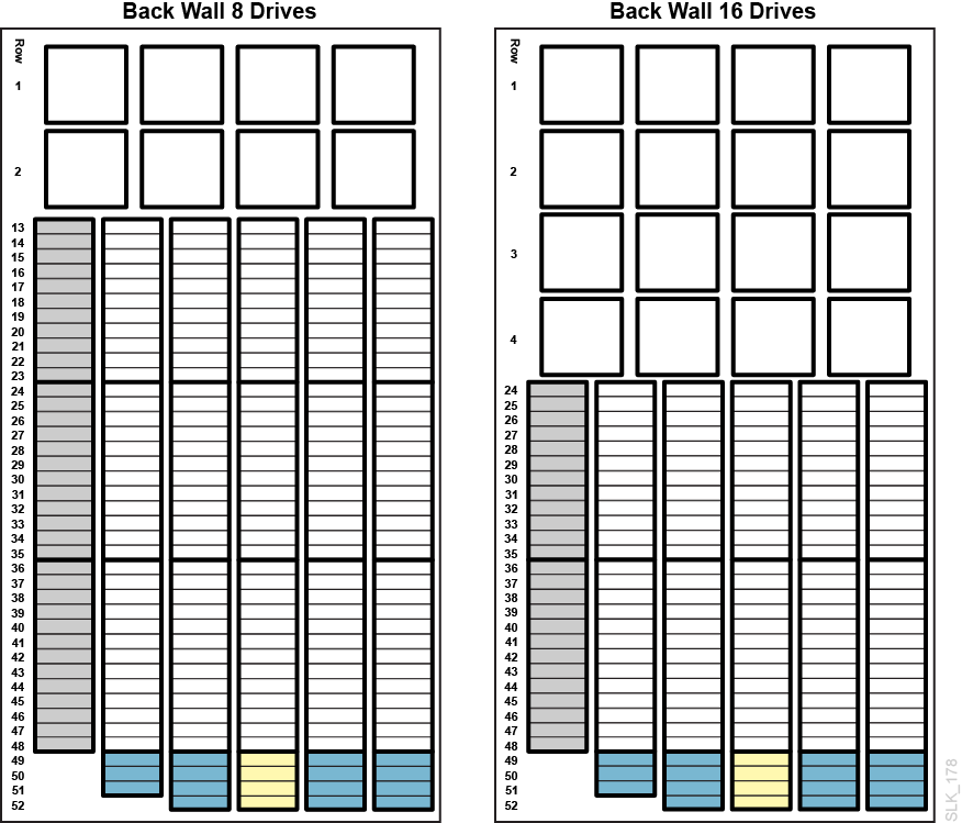
Figure 8-5 Drive Module - Back Wall 24 Drives and 32 Drives
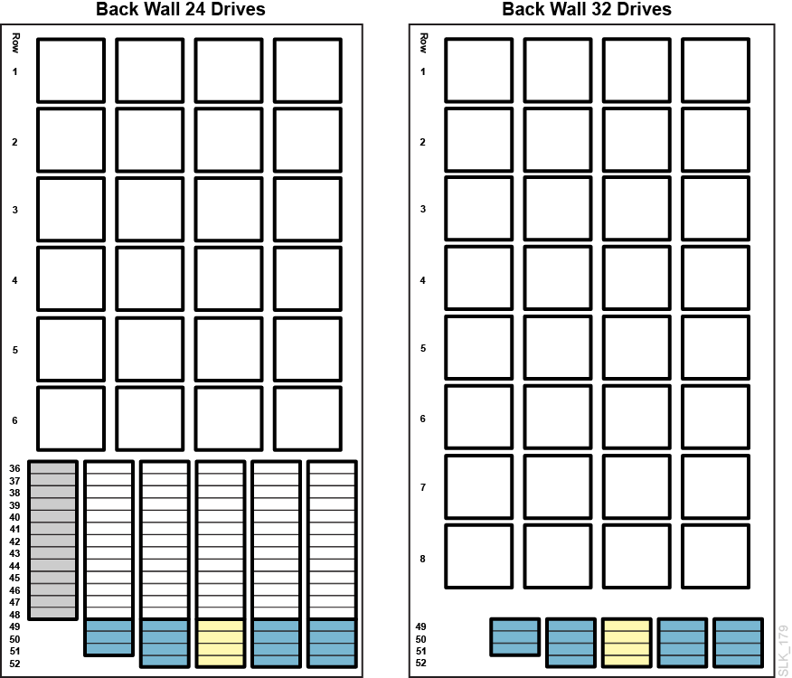
Figure 8-6 Cartridge Module - Front Wall
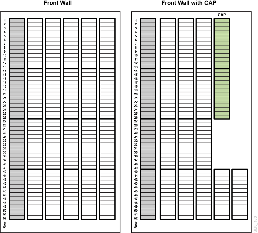
Figure 8-7 Cartridge Module - Back Wall
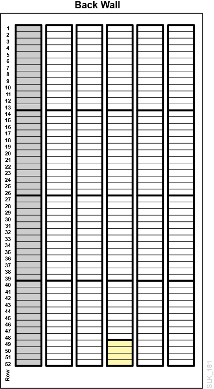
Figure 8-8 Parking Module, Left
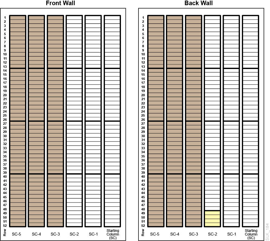
Figure 8-9 Parking Module, Right
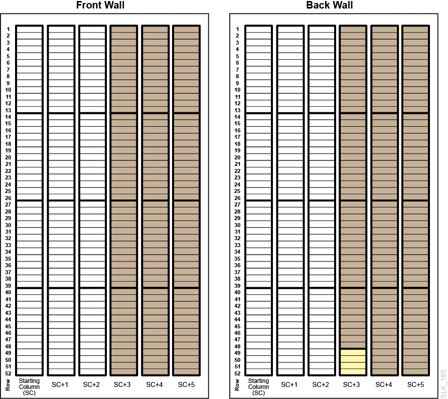
Figure 8-10 Access Module, Left
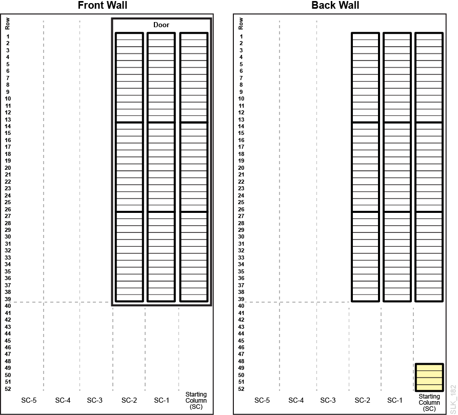
Figure 8-11 Access Module, Right
