Example: Replication Configuration for Clustered Appliances
The goal of this example is to configure replication properly to ensure that projects continue to replicate after a cluster takeover, cluster failback, or after performing reverse replication on a target appliance.
Configuration Guidelines
When configuring replication for clustered Oracle ZFS Storage Appliance systems, follow these guidelines:
-
Ensure that both replication source and target appliances are in the
CLUSTEREDstate. For details, see table "Cluster States" in Clustered Controller States. -
Select network interfaces and IP addresses to be used for replication traffic on the replication source and target appliances.
-
Select a singleton network interface. Unlike a private network interface, a singleton network interface will be taken over by the surviving controller following the loss of one of the controllers in the cluster. Using a singleton interface ensures successful replication following a cluster takeover or failback transition. For more information about singleton interfaces, see table "Cluster Resource Types" in Cluster Resource Management.
-
Ensure that the selected network interface on the source appliance and the pool from which the data will be replicated are both assigned to the same controller. This is always the case when the source cluster is in the
CLUSTEREDstate. -
Similarly for the target cluster, the selected network interface on the target appliance and the pool into which the data will be replicated must both be assigned to the same controller. This association is guaranteed when the replication configuration is performed while the target cluster is in
CLUSTEREDstate. -
The source and the target appliances must be able to successfully communicate using the selected network interfaces and IP addresses.
-
-
Create static /32 host-based routing between target and source appliances to ensure that following replication reversal, the selected interface is used for outbound replication traffic when reversal has transformed the current target into a replication source.
-
After the static route has been created, configure the replication target object on the source appliance using the selected IP address of the target.
-
When the target appliance is in the
OWNERstate, all shared resources including network interfaces and storage pools are taken over and owned by the one surviving controller, the controller that is now in theOWNERstate. On the controller in theOWNERstate, it is possible to select a network interface that is assigned to one controller and use it to deliver replication traffic to a pool that is assigned to a different controller. When the controllers are returned to theCLUSTEREDstate, the network interfaces and storage pools are returned to their assigned controllers. Therefore, replication updates might not be possible because the source appliance will use the network interface on the target controller that no longer owns the pool. This configuration error cannot arise when replication configuration is performed while the target appliance is in theCLUSTEREDstate.
Example: Configuring Replication for Clustered Appliances
The example procedure uses the following source and target network interfaces and IP addresses:
The source appliance cluster consists of source controllers S1 and
S2. Storage pool sp1 is assigned to
S1 and pool sp2 is assigned to
S2. The cluster network interfaces consist of:
-
Private interface
ixgbe0onS1with IP address 198.51.100.81/24 -
Private interface
ixgbe0onS2with IP address 198.51.100.82/24 -
Singleton interface
ixgbe1with IP address 192.0.2.101/25 assigned toS1 -
Singleton interface
ixgbe2with IP address 192.0.2.102/25 assigned toS2 -
Singleton interface
ixgbe3with IP address 192.0.2.201/25 assigned toS1 -
Singleton interface
ixgbe4with IP address 192.0.2.202/25 assigned toS2
The appliance is Initially in the CLUSTERED state where:
-
S1ownssp1,ixgbe1, andixgbe3 -
S2ownssp2,ixgbe2andixgbe4
The target appliance cluster consists of controllers T1 and
T2. Storage pool tp1 is assigned to
T1 and pool tp2 is assigned to
T2. The cluster network interfaces consist of:
-
Private interface
ixgbe0onT1with IP address 198.51.100.83/24 -
Private interface
ixgbe0onT2with IP address 198.51.100.84/24 -
Singleton interface
ixgbe1with IP address 192.0.2.103/25 assigned toT1 -
Singleton interface
ixgbe2with IP address 192.0.2.104/25 assigned toT2 -
Singleton interface
ixgbe3with IP address 192.0.2.203/25 assigned toT1 -
Singleton interface
ixgbe4with IP address 192.0.2.204/25 assigned toT2
The appliance is initially in the CLUSTERED state where:
-
T1ownstp1,ixgbe1,ixgbe3 -
T2ownstp2,ixgbe2andixgbe4
The following steps describe how to configure replication using the CLI for projects Red, Blue, and Green.
-
Select network interfaces and IP addresses.
-
Start by selecting network interfaces and IP addresses for replication of project
Red.Because the source
Sis in theCLUSTEREDstate, it is sufficient to ensure that the selected network interfaces and IP addresses are not private. Thus, onS1use eitherixgbe1orixgbe3. -
The same applies to target
T, therefore, use eitherixgbe1orixgbe3on applianceT1. Becauseixgbe1andixgbe3on bothS1andT1belong to the same subnet, select either to perform replication of projectRed. For this example, select interfaceixgbe1onS1and onT1.
-
-
Set up a static route on
S1.The following example sets up the static route for replication of project
Redon source controllerS1:S1:configuration net routing> create S1:configuration net route (uncommitted)> set family=IPv4 family = IPv4 (uncommitted) S1:configuration net route (uncommitted)> set destination=192.0.2.103 destination = 192.0.2.103 (uncommitted) S1:configuration net route (uncommitted)> set mask=32 mask = 32 (uncommitted) S1:configuration net route (uncommitted)> set interface=ixgbe1 interface = ixgbe1 (uncommitted) S1:configuration net route (uncommitted)> set gateway=192.0.2.1 gateway = 192.0.2.1 (uncommitted) S1:configuration net route (uncommitted)> commit S1:configuration net routing> list ROUTE DESTINATION GATEWAY INTERFACE TYPE STATUS ... route-003 192.0.2.103/32 192.0.2.1 ixgbe1 static active
-
Set up a static route on
T1.The following example sets the static route for replicating project
Redon target controllerT1:T1:configuration net routing> create T1:configuration net route (uncommitted)> set family=IPv4 family = IPv4 (uncommitted) T1:configuration net route (uncommitted)> set destination=192.0.2.101 destination = 192.0.2.101 (uncommitted) T1:configuration net route (uncommitted)> set mask=32 mask = 32 (uncommitted) T1:configuration net route (uncommitted)> set interface=ixgbe1 interface = ixgbe1 (uncommitted) T1:configuration net route (uncommitted)> set gateway=192.0.2.1 gateway = 192.0.2.1 (uncommitted) T1:configuration net route (uncommitted)> commit T1:configuration net routing> list ROUTE DESTINATION GATEWAY INTERFACE TYPE STATUS ... route-003 192.0.2.101/32 192.0.2.1 ixgbe1 static active
-
Create a replication target on
S1.The following example creates the replication target object on
S1to be used to replicate projectRedfromsp1totp1:S1:shares replication targets>target S1:shares replication target (uncommitted)> set hostname=192.0.2.103 hostname = 192.0.2.103 (uncommitted) S1:shares replication target (uncommitted)> set label=t1-1 label = t1-1 (uncommitted) S1:shares replication target (uncommitted)> set root_password=(set) root_password = (set) (uncommitted) S1:shares replication target (uncommitted)> commit
-
Create a replication action for each project.
-
Replicate project
Redfrom poolsp1totp1 -
Replicate project
Bluefrom poolsp1to pooltp2 -
Replicate project
Greenfrom poolsp2totp2
The following example creates the replication action for project
Red:S1:> shares select Red replication action S1:shares Red action (uncommitted)> set target=t1-1 target=t1-1 (uncommitted) S1:shares Red action (uncommitted)> set pool=tp1 pool=tp1 (uncommitted) S1:shares Red action (uncommitted)> commit
-
-
Set up to replicate project
Bluefrom poolsp1totp2.Start with interface and address selection, and select interfaces
S1/ixgbe3andT2/ixgbe4, knowing that bothSandTare in theCLUSTEREDstate and that the interface addresses are on the same subnet, 192.0.2.128/25. Next, define static routes on both appliances similar to the earlier examples. Then create replication target objectt2-2onS1, and create the replication action onS1for projectBlueusing target objectt2-2. -
Set up to replicate project
Greenfrom poolsp2totp2.Start with interface selection and select interfaces
S2/ixgbe2andT2/ixgbe2. Create static routes onS2andT2using the selected interfaces and their addresses, define replication target objectt2-1using address ofT2/ixgbe2, and finally create the replication action for projectGreenusing target objectt2-1. -
Initiate replication for all three actions.
-
Start with project
Red:S1:> shares select Red replication select action-000 S1:shares Red action-000> sendupdate
-
Initiate replication for the actions for projects
BlueandGreenby following the previous example.
-
Replication Data Path Illustrated Examples
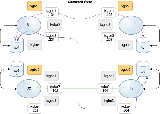
The following figures illustrate the replication data paths during replication updates for the replication actions for projects Red, Blue, and Green:
Normal Replication Data Path

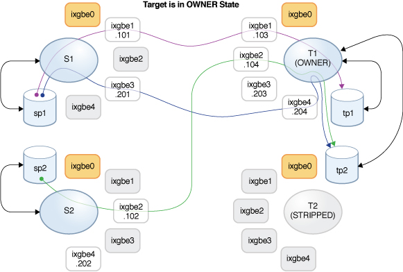
Assume that controller T2 has been taken down for a maintenance. T1 performed a takeover and now owns all of the resources. If replication updates for projects Blue and Green are in progress during the takeover, they will be canceled. After T1 takes over, these replication updates can be resumed manually, or they will be resumed automatically if schedules are configured for the corresponding replication actions.
After controller T1 has completed the takeover, it owns interfaces ixgbe2 and ixgbe4 which are necessary to continue replication updates for projects Blue and Green. The following figure shows the replication data path after T1 completed the takeover.
Replication Data Path After T1 Takeover

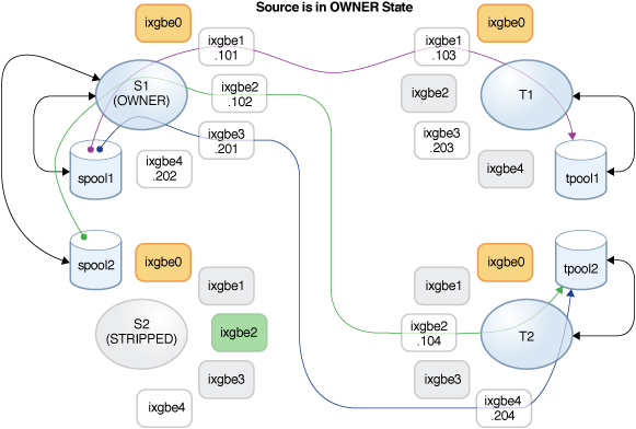
After T2 is back online, a failback is performed on the T1 controller and it takes over its resources. If replication updates of projects Blue and Green are in progress, they will be canceled and can be resumed following the completion of the failback.
Then controller S2 is taken down for maintenance, and the takeover performed on the S1 controller causes it to take ownership of all of the resources, including the interface required for continuing replication of project Green. If a replication update of project Green is in progress, it will be canceled and can be resumed following the completion of the takeover.
Data Path After Failback on T1 and Takeover on S1

Related Topics