Oracle ZFS Storage ZS5-4 Internal Components
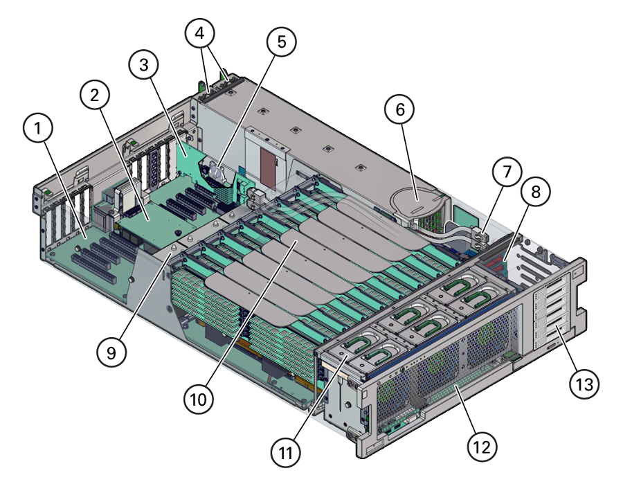
The components of the Oracle ZFS Storage ZS5-4 controller are shown in the following figure and identified in the legend.
|
1 Motherboard |
8 Storage drive backplane board |
|
2 SP card |
9 Heatsinks and CPUs (4) |
|
3 HBA card |
10 Memory riser cards (8) |
|
4 Power supplies (2) |
11 Fan modules (6) |
|
5 System battery |
12 Fan board |
|
6 Power supply backplane |
13 Storage drive slots (2) |
|
7 HBA SAS cables (2) |
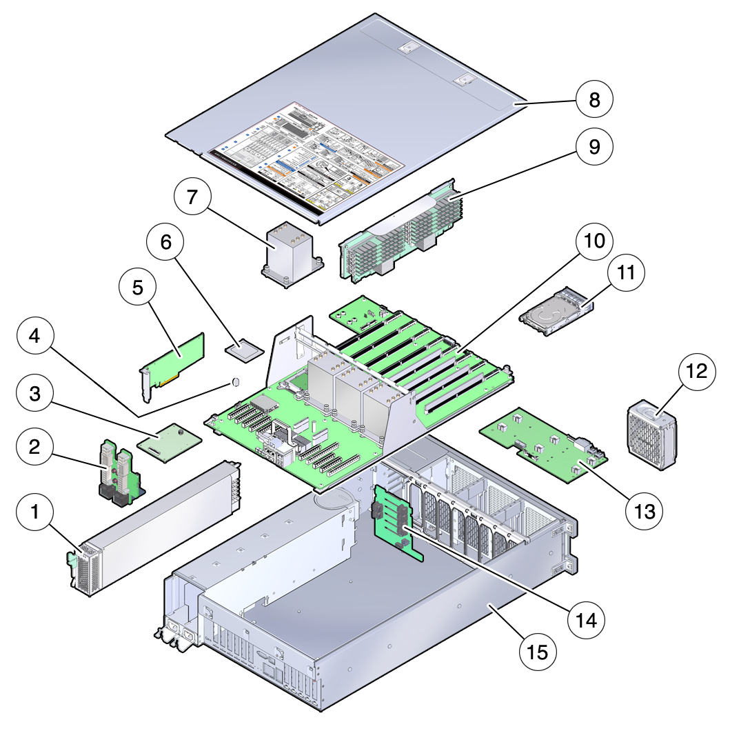
Oracle ZFS Storage ZS5-4 Internal Components (Exploded View)
|
1 Power supplies |
9 Memory riser card |
|
2 Power supply backplane board |
10 Motherboard |
|
3 SP card |
11 Storage drive |
|
4 System battery |
12 Fan module |
|
5 HBA card |
13 Fan board |
|
6 CPU |
14 Storage drive backplane board |
|
7 Heatsink |
15 Controller chassis |
|
8 Cover |
Oracle ZFS Storage ZS5-4 Storage Drive
This section shows the location and explains the functions of the storage drive status indicators.

|
1 Ready to Remove (blue) |
2 Service Action Required (amber) |
3 OK/Activity (green) |
Oracle ZFS Storage ZS5-4 Fan Module
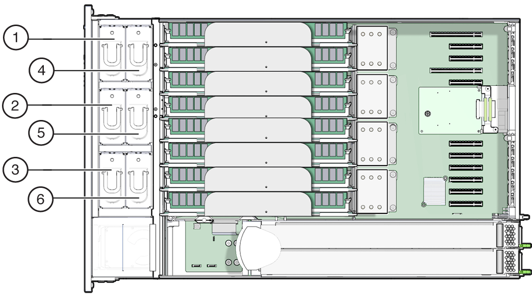
The six fan module slots are at the front of the Oracle ZFS Storage ZS5-4 controller and are set in two rows of three slots. The slots are designated from left to right. As pictured in the illustration below, the three front row slots are designated as: FM0, FM1, and FM2. The three back row slots are: FM3, FM4, and FM5.
|
1 Fan Module, FM 0 |
3 Fan Module, FM 2 |
5 Fan Module, FM 4 |
|
2 Fan Module, FM 1 |
4 Fan Module, FM 3 |
6 Fan Module, FM 5 |
Oracle ZFS Storage ZS5-4 Power Supply
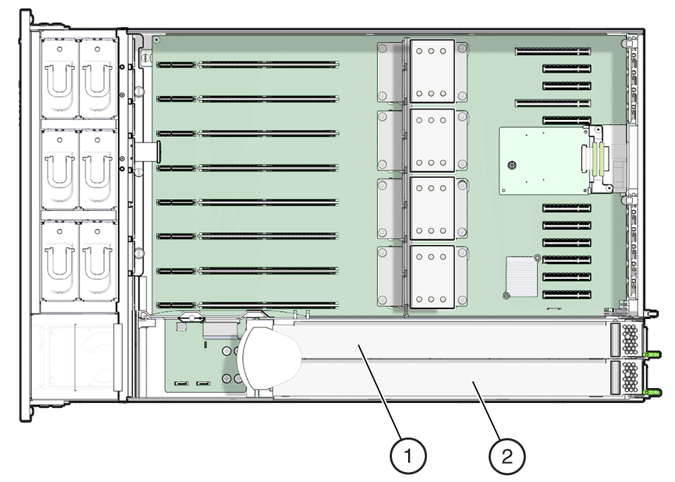
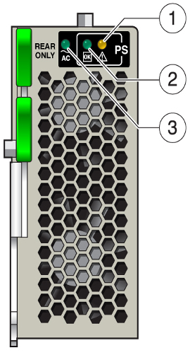
The two power supply slots are located on the right side of the Oracle ZFS Storage ZS5-4 controller (from the front of the controller) and are designated from right to left. The slots are accessible from the back of the controller. From the back of the controller, the left slot is designated as PS-0, and the right slot is PS-1.
|
1 PS 1 |
2 PS 0 |
The two power supplies ensure redundancy by allowing the controller to operate when one of the power supplies fails. However, when the controller is operating on one power supply, redundancy no longer exists, and the risk for an unexpected shut down and a loss of data is high. When a power supply or any component that is part of a redundant configuration fails, replace it immediately.
|
1 Service Action Required (amber) |
2 DC OK (green) |
3 AC OK (green) |
Oracle ZFS Storage ZS5-4 DIMM
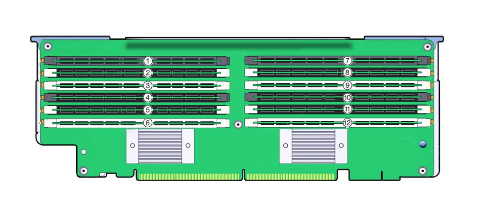
The DIMM slots are located on the memory riser cards. The DIMMs are arranged in two banks of six slots for a total of 12 slots. The slots are designated numerically from top to bottom. The left bank of slots are designated as D0–D6. The right bank of slots are designated as D7–D11.
|
1 Slot D0 |
4 Slot D3 |
7 Slot D6 |
10 Slot D9 |
|
2 Slot D1 |
5 Slot D4 |
8 Slot D7 |
11 Slot D10 |
|
3 Slot D2 |
6 Slot D5 |
9 Slot D8 |
12 Slot D11 |
Memory Riser layout:
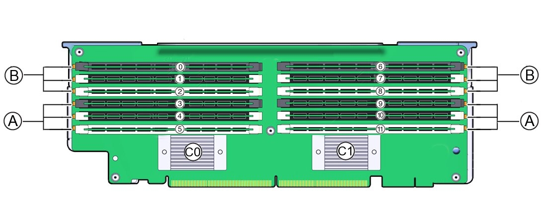
The following illustration shows the DIMM slot and channel designations on the memory riser card:
|
0 - 11 DIMM slot numbers. Board labeling prepends a "D" to the slot number (for example: D0–D11). |
|
B Channel B slots: D0–D2 for memory buffer 0, D6–D8 for memory buffer 1. |
|
A Channel A slots: D3–D5 for memory buffer 0, D9–D11 for memory buffer 1. |
|
C0 Memory buffer 0 |
|
C1 Memory buffer 1 |
Oracle ZFS Storage ZS5-4 Storage Drive and USB
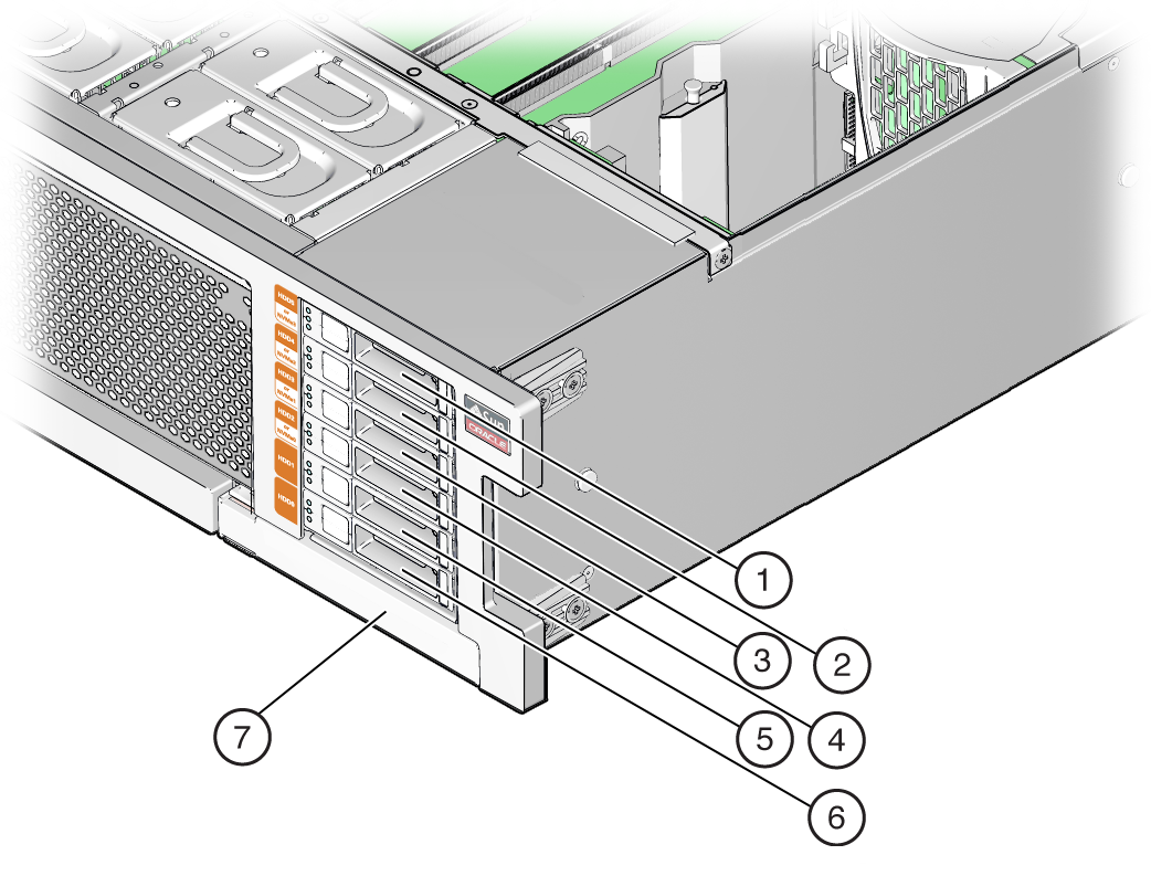
The storage drive slots are on the right side of the Oracle ZFS Storage ZS5-4 controller and are designated consecutively from bottom to top.
|
1 Drive Filler Panel |
5 Secondary Boot Drive |
|
2 Drive Filler Panel |
6 Primary Boot Drive |
|
3 Drive Filler Panel |
7 DVD Filler Panel |
|
4 Drive Filler Panel |