Replacing a Disk Shelf Power Supply

Caution:

Do not remove a component if you do not have an immediate replacement. The disk shelf must not be operated without all components in place, including filler panels. Refer to Disk Shelf Hardware Overview for component locations.

Disk shelves are provided with redundant power supplies to prevent loss of service due to component failure. Each power supply is accompanied by one or more chassis cooling fans in one customer-replaceable unit (CRU). Power supplies are hot-swappable, meaning they can be replaced one at a time without removing power from the disk shelf.

Caution:

The modules can produce a high-energy hazard and should only be replaced by instructed individuals with authorized access to the equipment.
  1. Separate indicator LEDs on the back panel represent the operational state of power supplies and fans individually; see the rear panel illustration for details. Failed components are indicated by amber LEDs as well as amber icons in the administrative BUI. From the Maintenance BUI menu, select Hardware, click the right-arrow icon apply icon at the beginning of the appropriate disk shelf row, then select PSU or Fan to view details on the respective components. You can also click the locator icon locate icon to flash the chassis locator LED.
  2. Locate the chassis and module containing the failed component.
  3. Ensure the power supply on/off switch is in the "O" off position.

    Some power supplies for Oracle Storage Drive Enclosure DE3-24P and DE3-24C disk shelves have a disabled on/off switch with a do-not-use label ( icon symbolizing "do not use" ) on the switch. If the disk shelf has this power supply, skip this step and continue with the next step.

  4. Disconnect the power cord tie strap from the power cord, and unplug the power cord from the power supply.
  5. Release the lever/ejection arms. Pull the module out of the chassis, being careful not to damage the connector pins in the back.

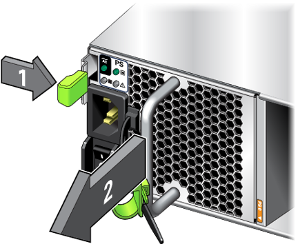
    Oracle Storage Drive Enclosure DE3-24P or DE3-24C:

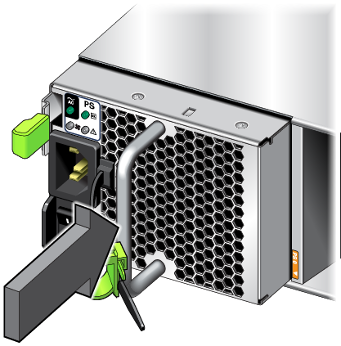
    To release the lever, push the lever fully downward.


    Graphic showing how to remove an Oracle Storage Drive Enclosure DE3-24 disk shelf power supply module

    Oracle Storage Drive Enclosure DE2-24P, DE2-24C or DE3-12C:

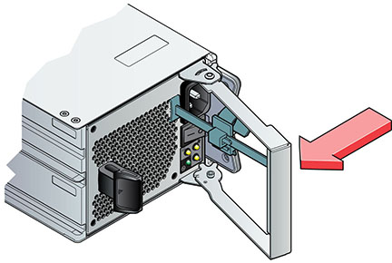
    To release the lever, grasp the latch and the opposite side of the module, and squeeze together to release the lever.


    Graphic showing how to remove an Oracle Storage Drive Enclosure DE2-24 or Oracle Storage Drive Enclosure DE3-12C disk shelf power supply module

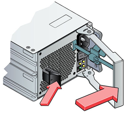
    Sun Disk Shelf:

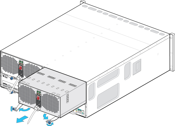
    To release the arms, use your thumb and forefinger, unscrew both ejection arm captive screws until loose, and swing the ejection arms out until they are fully open.


    Graphic showing how to remove a Sun Disk Shelf power supply module
  6. With the lever/ejection arms fully open (if applicable), slide the new module into the chassis slot until it contacts the chassis backplane, and the lever/ejection arms begin to engage. Close the lever/ejection arms. If an Oracle Storage Drive Enclosure DE3-24, the module clicks in place and the lever engages.

    Oracle Storage Drive Enclosure DE3-24P or DE3-24C:

    Push on the handle until you hear or feel a click.


    Graphic showing how to install an Oracle Storage Drive Enclosure DE3-24 disk shelf power supply module

    Oracle Storage Drive Enclosure DE2-24P, DE2-24C or DE3-12C:

    Push the lever fully closed until you hear or feel a click.


    Graphic showing how to install an Oracle Storage Drive Enclosure DE2-24 or Oracle Storage Drive Enclosure DE3-12C disk shelf power supply module

    Sun Disk Shelf:

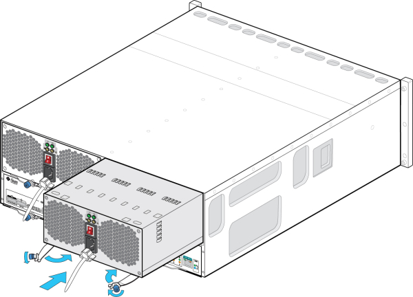
    Push the ejection arms fully closed and secure both captive screws to seat and secure the module in the chassis.


    Graphic showing how to install a Sun Disk Shelf power supply module
  7. Ensure the power supply on/off switch is in the "O" off position. Plug the power cord into the new power supply and attach the power cord tie strap to the power cord.

    If the disk shelf has a power supply with a disabled on/off switch, do not place the switch in the off position.

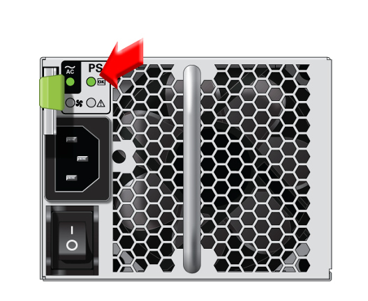
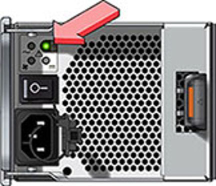
  8. Place the power supply on/off switch to the "I" on position. The Power/OK status LED should be a steady green, and all other indicators should be off.

    If the disk shelf has a power supply with a disabled on/off switch, do not place the switch in the on position.

    Oracle Storage Drive Enclosure DE3-24P or DE3-24C:


    image showing how to check power status

    Oracle Storage Drive Enclosure DE2-24P, DE2-24C or DE3-12C:


    image showing how to check power status
  9. From the Maintenance BUI menu, select Hardware, and click the right-arrow icon apply icon at the beginning of the appropriate disk shelf row. As appropriate for the failure, click either PSU or Fan to verify that the online icon light on icon is green for the newly installed power supply with fan module.
  10. If a fault does not self-clear, see Repairing Active Problems.