Replacing an Oracle ZFS Storage ZS9-2 Power Supply

Caution:

If a power supply fails and you do not have a replacement available, do not remove the failed power supply. This maintains the proper air flow and prevents possible equipment damage.

Controllers are equipped with highly redundant, hot-swappable power supplies: Either two A269.2 1200W power supplies or two A271 1400W power supplies. The A269.2 1200W power supply accepts ranges of 100-127 volts AC (VAC) low-line or 200-240 VAC high-line, and the A271 1400W power supply only accepts ranges of 200-240 VAC high-line. High-line power supplies require high-line 200-240 VAC sources.

Use the following procedure to replace an Oracle ZFS Storage ZS9-2 power supply.

Caution:

Mixing A269.2 and A271 power supplies within the same chassis is not supported.
  1. Identify the faulted power supply.
    • If you are not physically at the system, from the Maintenance BUI menu, select Hardware, click the right-arrow icon apply icon for the controller, click PSU, and note the ID of the faulted power supply, which has an amber icon. To highlight the location of the power supply in the controller picture, click on the power supply ID. To view details about the faulted power supply, click its information icon information icon and then click Active Problems.

    • If you are physically at the system, the amber Service Action Required indicator on the power supply should be lit.

    Note:

    The fans of a failed power supply might still be spinning when the system is powered on. You can remove a power supply while the fans are still spinning. The fans will stop spinning when you disconnect the power cords.

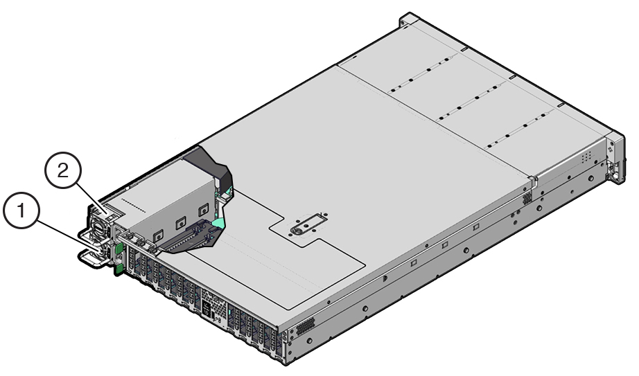
    Figure identifying PS0 and PS1.

    1 Power supply 0

    2 Power supply 1

  2. Gain access to the rear of the controller where the failed power supply is located.
  3. If the cable management arm (CMA) is installed, disconnect both CMA left-side connectors and move the CMA out of the way.

    For the location of the CMA left-side connectors, see Installing an Oracle ZFS Storage ZS9-2 Cable Management Arm in Oracle ZFS Storage Appliance Installation Guide, Release OS8.8.x.

    Caution:

    When disconnecting the CMA left-side connectors, be sure to use your arm to support the CMA so that it does not hang down under its own weight and stress the right-side connectors; otherwise, the CMA could be damaged. You must continue to support the CMA until you have reconnected both of the left-side connectors.
  4. Disconnect the power cord from the failed power supply.
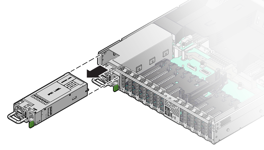
  5. Grasp the power supply handle and push the power supply latch to the left.

    Figure showing a power supply being removed from the controller. Specifically shows the location of the power supply latch.
  6. Pull the power supply out of the controller.

    Caution:

    Whenever you remove a power supply, you should replace it with another power supply; otherwise, the controller could overheat due to improper airflow.
  7. Remove the replacement power supply from its packaging, and place it on an antistatic mat.

    Caution:

    Always replace the failed power supply with the same type model of power supply.
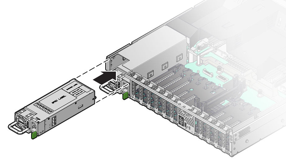
  8. Align the replacement power supply with the empty power supply slot.
  9. Slide the power supply into the slot until it is fully seated.

    You will hear or feel a click when the power supply fully seats.


    Figure showing a power supply being installed into the controller.
  10. Reconnect the power cord to the power supply.
  11. Verify that the amber Fault-Service Required LED on the replaced power supply, and the Fault-Service Required LEDs are not lit on the front and back panels.

    Note:

    After you have replaced Power Supply 0, you might need to reset the Oracle ILOM service processor (SP) to propagate the key identity properties (KIP) data to the new power supply. For instructions on resetting the SP, refer to the Oracle Integrated Lights Out Manager (ILOM) 5.0 Configuration and Maintenance Guide Firmware Release 5.0.x at https://www.oracle.com/goto/ilom/docs . Power Supply 1 does not contain KIP data, and therefore does not require an SP reset after replacement.
  12. If you disconnected the two CMA left-side connectors, reconnect the connectors.
  13. From the Maintenance BUI menu, select Hardware. Click the right-arrow icon apply icon for the controller, click PSU, and verify that the status icon light on icon is green for the newly installed power supply. To view details about the new power supply, click its information icon information icon.
  14. If a fault does not self-clear, see Repairing Active Problems.