Networks
With Oracle Linux Virtualization Manager, you can create custom vNICs for virtual machines.
Note:
If you plan to use VLANs on top of bonded interfaces, see the My Oracle Support (MOS) article How to Configure 802.1q VLAN on NIC (Doc ID 1642456.1) for instructions.Creating a Logical Network
To create a logical network:
-
Go to Network and then select Networks.
-
On the Networks pane, select New.
The New Logical Network dialog box opens with the General tab selected on the sidebar.
-
From the Data Center dropdown list, select the Data Center for the network.
The Default data center is preselected in the dropdown list.
For the procedures to create new data centers or a new clusters, see Data Centers or Clusters tasks.
-
For the Name field, enter a name for the new network.
-
Under the Network Parameters section, the VM Network checkbox is selected by default. Leave the VM Network checkbox selected to create a new virtual machine network.
-
(Optional) Configure other settings for the new logical network from the other tabs on the New Logical Network sidebar.
-
Select OK to create the network.
Assigning a Logical Network to a KVM Host
To assign a logical network to a KVM host:
-
Go to Compute and then select Hosts.
The Hosts pane opens.
-
Under the Name column, select the name of the host for which to add the network.
The following screenshot shows the Hosts pane with the name of the host highlighted in a red rectangular box to emphasize where you need to select to set up a network on a host.
Figure 3-1 Hosts Pane

After selecting the name of the host, the General tab opens with details about the host.
-
Select the Network Interfaces tab on the horizontal menu.
The Network Interfaces tab opens with details about the network interfaces on the available host.
-
Highlight the network interface that you want to use for the network being added by selecting the row for the respective interface.
-
Select Setup Host Networks.
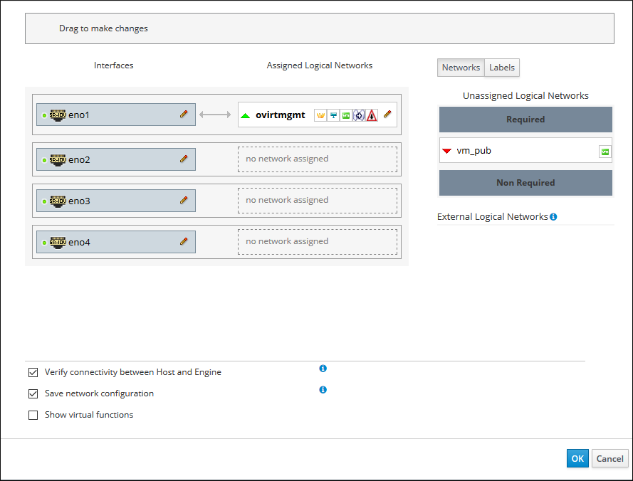
The Setup Host Networks dialog box opens for the host. The physical interfaces on the host are listed under the Interfaces column and any logical networks assigned to the interface are displayed under the Assigned Logical Networks column. Unassigned logical networks are displayed under the Unassigned Logical Networks column.
In the following example screenshot, a logical network named
vm_pubis displayed under the Unassigned Logical Networks column.Figure 3-2 Setup Host Dialog Box: Unassigned Logical Networks

-
Select the network you want to add from the Unassigned Logical Networks column by selecting the network and, while holding down the mouse, drag the network over to the box to the right of the available network interface where you want to add the network.
Or, you can right-click the network and select the available interface from a dropdown list.
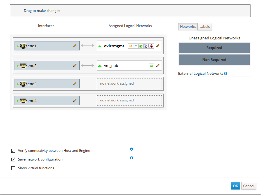
For example, the logical network named
vm_pubis assigned to the available network interface namedeno2. In the following screenshot, after dragging the network from Unassigned Logical Networks over to this interface, the network namedvm_pubappears under the Assigned Logical Networks column as assigned to the network interface namedeno2.Figure 3-3 Setup Host Dialog Box: Assigned Logical Networks

-
After editing the network settings, select OK to save the settings.
-
Select OK to add the network.
Customizing vNIC Profiles for Virtual Machines
To customize vNICs for virtual machines:
-
Go to Compute and then select Virtual Machines.
The Virtual Machines pane opens with the list of virtual machines that have been created.
-
Under the Name column, select the virtual machine for which to add the virtual machine network.
The General tab opens with details about the virtual machine.
-
Select the Network Interfaces tab.
The Network Interfaces tab opens with the available network interface to be used for the network.
-
Highlight the network interface by selecting the row for the respective interface and then select Edit on the right side above the interface listing.
The Edit Network Interface dialog box opens.
-
In the Edit Network Interface dialog box, update the following fields:
-
From the Profile dropdown list, select the network to be added to the virtual machine.
-
Select the Custom MAC address checkbox. Then enter or update the MAC address that's allocated for this virtual machine in the text entry field.
-
-
Select OK when you're finished editing the network interface settings for the virtual machine.
-
Go to Compute and then select Virtual Machines.
The Virtual Machines pane opens.Important:
Because virtual machines can start on any host in a data center/cluster, all hosts must have the customized VM network assigned to one of its NICs. Ensure that you assign this customized VM network to each host before booting the virtual machine. For more information, see Assigning a Logical Network to a KVM Host.
-
Highlight the virtual machine where you added the network and then select Run to boot the virtual machine.
The red down arrow icon to the left of the virtual machine turns green and the Status column displays
UPwhen the virtual machine is up and running on the network.
Attaching and Configuring a Logical Network to a Host Network Interface
You can change the settings of physical host network interfaces, move the management network from one physical host network interface to another, and assign logical networks to physical host network interfaces.
Before you begin the steps below, consider the following:
-
To change the IP address of a host, you must remove the host and then readd it.
-
To change the VLAN settings of a host, see Editing a Host's VLAN Settings in oVirt Documentation.
-
You can't assign logical networks offered by external providers to physical host network interfaces; such networks are dynamically assigned to hosts as they're required by virtual machines.
-
If a switch has been configured to provide Link Layer Discovery Protocol (LLDP) information, you can hover the cursor over a physical network interface to view the switch port’s current configuration.
Note:
Before assigning logical networks, check the configuration. To help detect to which ports and on which switch the host’s interfaces are patched, review Port Description (TLV type 4) and System Name (TLV type 5). The Port VLAN ID shows the native VLAN ID configured on the switch port for untagged ethernet frames. All VLANs configured on the switch port are shown as VLAN Name and VLAN ID combinations.
To edit host network interfaces and assign logical networks:
-
Select Compute Hosts.
-
Select the host’s name. This opens the details view.
-
Select the Network Interfaces tab.
-
Select Setup Host Networks.
-
Optionally, hover the cursor over host network interface to view configuration information provided by the switch.
-
Attach a logical network to a physical host network interface by selecting and dragging the logical network into the Assigned Logical Networks area next to the physical host network interface.
If a NIC is connected to more than one logical network, only one of the networks can be non-VLAN. All the other logical networks must be unique VLANs.
-
Configure the logical network.
-
Hover the cursor over an assigned logical network and select the pencil icon. This opens the Edit Management Network window.
-
Configure IPv4 or IPv6:
-
From the IPv4 tab, set the Boot Protocol. If you select Static, enter the IP, Netmask / Routing Prefix, and the Gateway.
-
From the IPv6 tab:
-
Set theBoot Protocol to Static.
-
For Routing Prefix, enter the length of the prefix using a forward slash and decimals. For example: /48 IP:
-
In the IP field, enter the complete IPv6 address of the host network interface. For example: 2001:db8::1:0:0:6
-
In the Gateway field, enter the source router’s IPv6 address. For example: 2001:db8::1:0:0:1
-
Note:
If you change the host’s management network IP address, you must reinstall the host for the new IP address to be configured.
Each logical network can have a separate gateway defined from the management network gateway. This ensures traffic that arrives on the logical network is forwarded using the logical network’s gateway instead of the default gateway used by the management network.
Set all hosts in a cluster to use the same IP stack for their management network; either IPv4 or IPv6 only.
-
-
To configure a network bridge, select the Custom Properties tab, select bridge_opts from the list, and enter a valid key and value with the syntax of
key=value.The following are valid keys with example values:
forward_delay=1500
group_addr=1:80:c2:0:0:0
group_fwd_mask=0x0
hash_max=512
hello_time=200
max_age=2000
multicast_last_member_count=2
multicast_last_member_interval=100
multicast_membership_interval=26000
multicast_querier=0
multicast_querier_interval=25500
multicast_query_interval=13000
multicast_query_response_interval=1000
multicast_query_use_ifaddr=0
multicast_router=1
multicast_snooping=1
multicast_startup_query_count=2
multicast_startup_query_interval=3125
Separate multiple entries with a whitespace character.
-
To configure ethernet properties, select the Custom Properties tab, select ethtool_opts from the list, and enter a valid value using the format of the commandline arguments of
ethtool. For example:--coalesce em1 rx-usecs 14 sample-interval 3 --offload em2 rx on lro on tso off \ --change em1 speed 1000 duplex halfYou can use wildcard to apply the same option to all a network's interfaces, for example:
--coalesce * rx-usecs 14 sample-interval 3The
ethtool_optsoption isn't available by default; you need to add it using the engine configuration tool. To viewethtoolproperties, from a command line typeman ethtoolto open the man page. For more information, see How to Set Up oVirt Engine to Use Ethtool in oVirt Documentation. -
To configure Fibre Channel over Ethernet (FCoE), select the Custom Properties tab, select fcoe from the list, and enter
enable=yes. Separate multiple entries with a whitespace character.The
fcoeoption isn't available by default; you need to add it using the engine configuration tool. For more information, see How to Set Up oVirt Engine to Use FCoE in oVirt Documentation. -
To change the default network used by the host from the management network (ovirtmgmt) to a non-management network, configure the non-management network’s default route. For more information, see Configuring a Non-Management Logical Network as the Default Route in oVirt Documentation.
-
If the logical network definition isn't synchronized with the network configuration on the host, select the Sync network checkbox. For more information about unsynchronized hosts and how to synchronize them, see Synchronizing Host Networks in oVirt Documentation.
-
-
To check network connectivity, select the Verify connectivity between Host and Engine checkbox.
Note:
The host must be in maintenance mode.
-
Select OK.
Note:
If not all network interface cards for the host are displayed, select Management and then Refresh Capabilities to update the list of network interface cards available for that host.