Prerequisites
This section describes how to set up network connectivity between the primary database and the standby database across zones or regions for Data Guard.
You can route traffic by using either the Oracle Cloud Infrastructure network or the Azure network.
The following steps describe how to configure cross-zone and cross-region setups. These steps apply to Oracle Exadata Database Service on Dedicated Infrastructure, Oracle Exadata Database Service on Exascale Infrastructure and Oracle Base Database Service.
After you set up connectivity, follow the Data Guard documentation to enable replication.
For Application continuity configuration, and Maximum Availability Architecture (MAA), see Oracle Maximum Availability Architecture for Oracle AI Database@Azure.
Cross-Zone
This section guides you through the complete setup of the network configuration to establish data replication by using either an OCI network or a Azure network across Azure availability zones.
It is recommended to run production workloads in Oracle AI Database@Azure in two Availability Zones (AZs) to use Azure multi-AZ infrastructure. This approach protects critical databases from primary Availability Zone availability issues. The following sections describe connectivity options for cross-AZ Data Guard deployment by using the OCI network and the Azure network.
Connectivity by OCI Network
The following diagram illustrates the architecture diagram for configuring cross-AZ by OCI network.
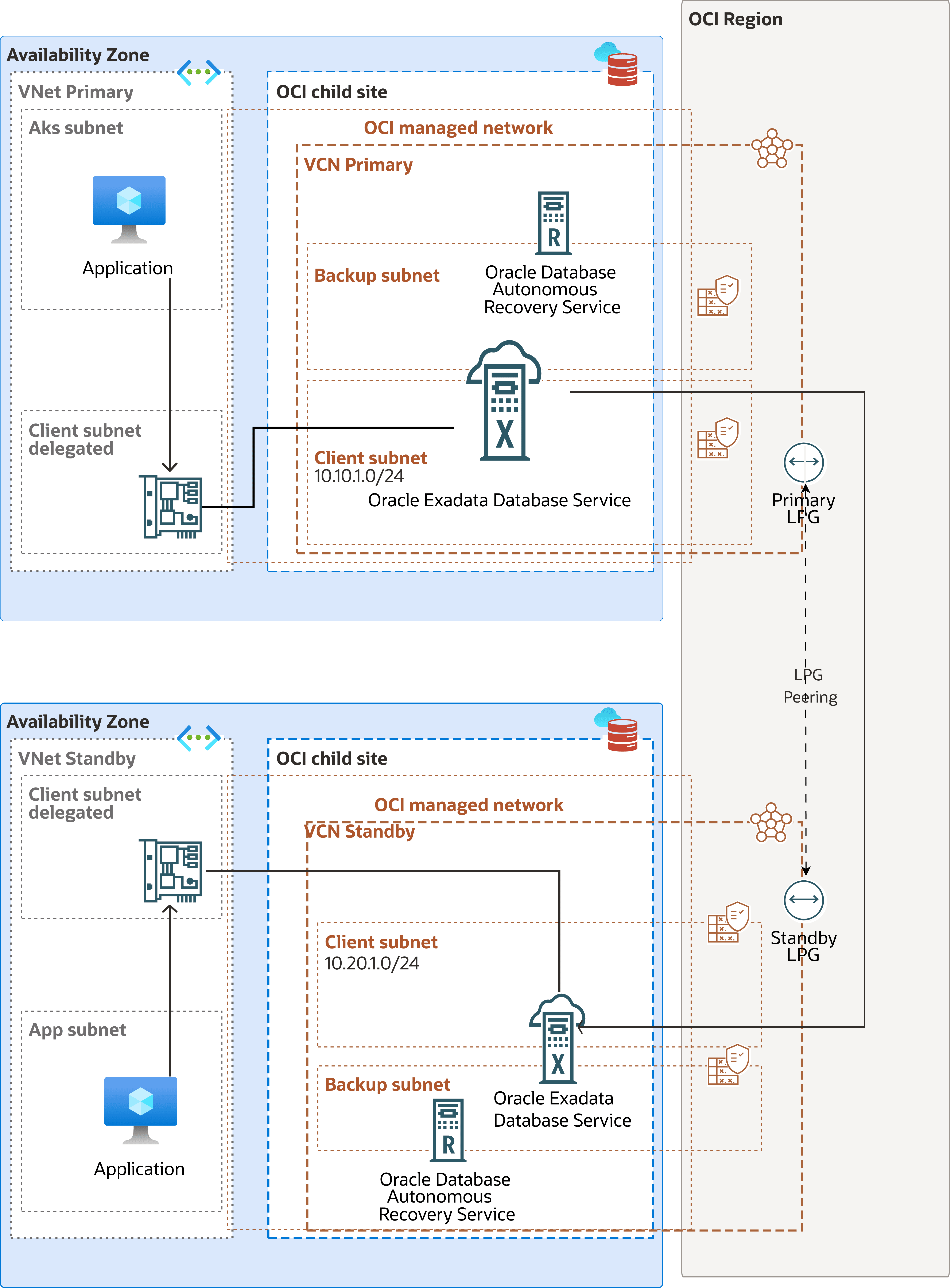
Oracle AI Database@Azure runs in an Exadata Database, Exascale VM Cluster or Base Database in the primary availability zone. For data protection, Oracle Data Guard replicates the data to a different availability zone (local standby) in the same region. A local standby is ideal for failover scenarios, offering zero data loss for local failures while applications continue operating without the performance overhead of communicating with a remote region.
You can route Data Guard traffic through the Azure network. In this architecture, it directs Active Data Guard network traffic through the OCI network to optimize network throughput and latency. The VCNs on the OCI site are created after the Exadata VM Cluster(s) on Oracle AI Database@Azure are created for the primary and standby databases.
In this architecture:- The primary Exadata VM Cluster is deployed in the primary availability zone in VCN1 with CIDR 10.10.0.0/16 and client subnet CIDR 10.10.1.0/24.
- VCN1 has a Local Peering Gateway LPG1.
- The standby Exadata VM Cluster is deployed in the standby availability zone in VCN2 with CIDR 10.20.0.0/16 and client subnet CIDR 10.20.1.0/24.
- VCN2 has a Local Peering Gateway LPG2.
- VCN1 and VCN2 are peered with a Local Peering Connection via LPG1 and LPG2.
Establish the local peering between the VCNs of the primary and standby Exadata VM Clusters and configure the route tables and security lists to enable network communication for Active Data Guard between the availability zones.
Configure the Network in the Primary Zone
Configure the network in the primary zone by using the following steps:
- From the OCI console, scroll down to the Network section, then select the Virtual Cloud Network.
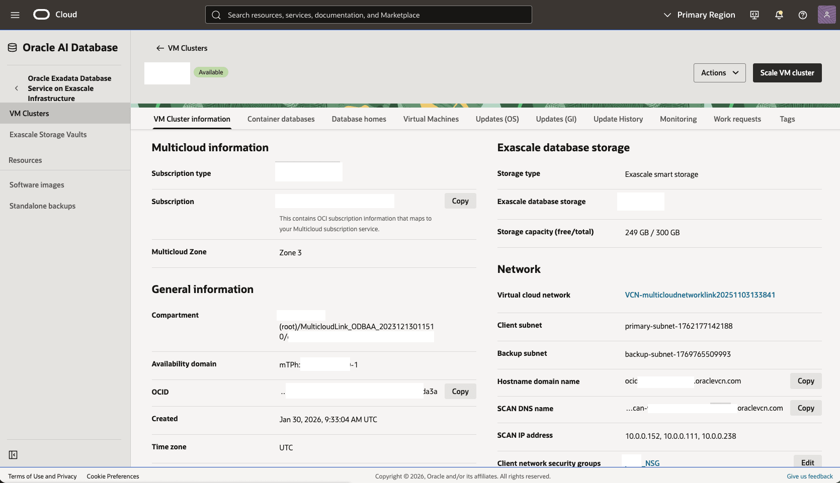
- In the Virtual Cloud Networks detail page, select the Gateways tab.
- Scroll down to the Local Peering Gateways section, and then select the Create Local Peering Gateway button.
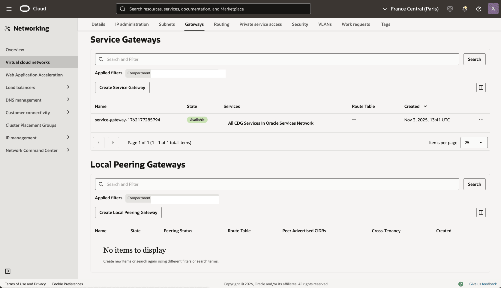
- Choose a name, for example,
Primary-LPG, and then select the Create Local Peering Gateway button. Record the local peering gateway OCID. - The Advanced options section is optional.
- Select the Create Local Peering Gateway button.
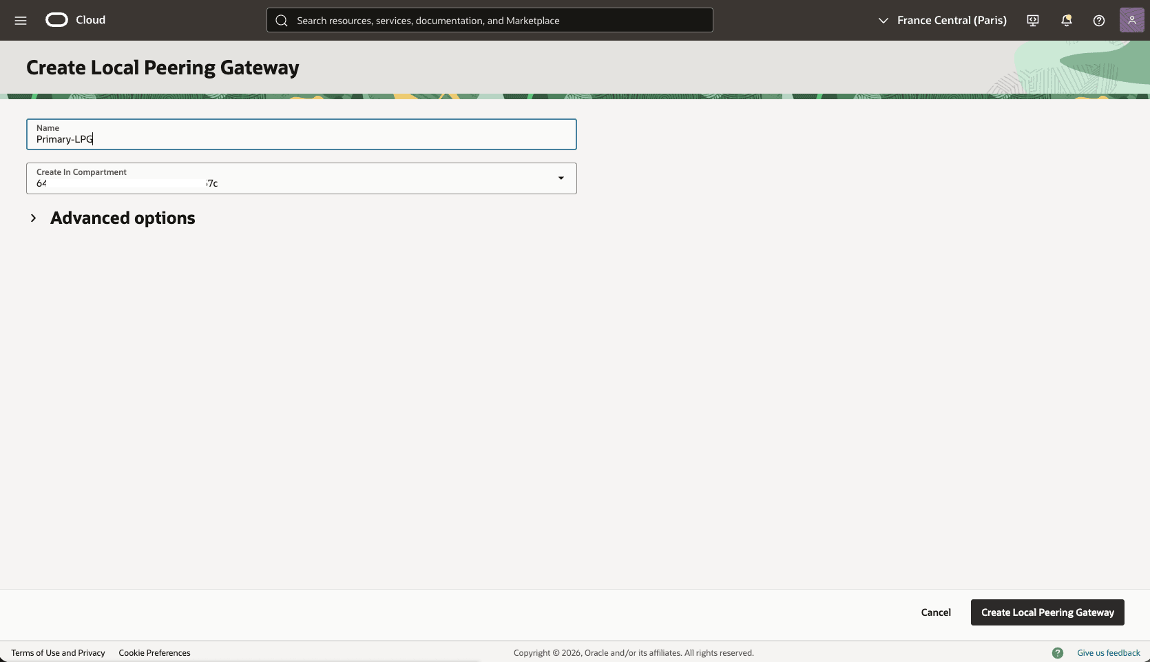
- Choose a name, for example,
- Update the OCI network security group for your primary VM cluster to allow traffic from the standby network.
- In the Virtual Cloud Networks detail page, select the Security tab, scroll down to the Network Security Groups section, and then select the name of your VM Cluster Network Security Groups.
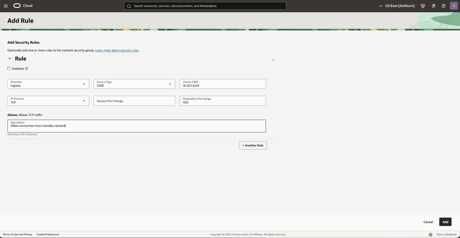
- Select the Security rules tab. Select Add Rules, and then create a rule with the following specifications.
- Direction: Ingress
- Source Type: CIDR
- Source CIDR: Enter your stand by CIDR block. For example,
10.20.1.0/24 - IP Protocol: TCP
- Source Port Range: Empty (All)
- Destination Port Range: 1521
- Description: Enter a description for this rule,
- Select the Add button.
- Add a route rule to the default route table in the primary VCN to route standby traffic to Primary-LPG.
- In the primary Virtual Cloud Networks detail page, select the Routing tab, select the name of your default route table.
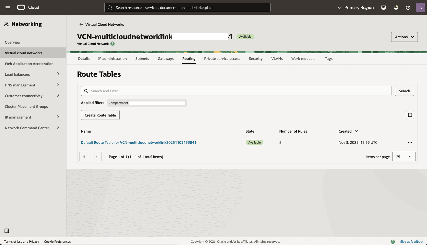
- Select the Route Rules tab, and then select the Add Route Rules button.
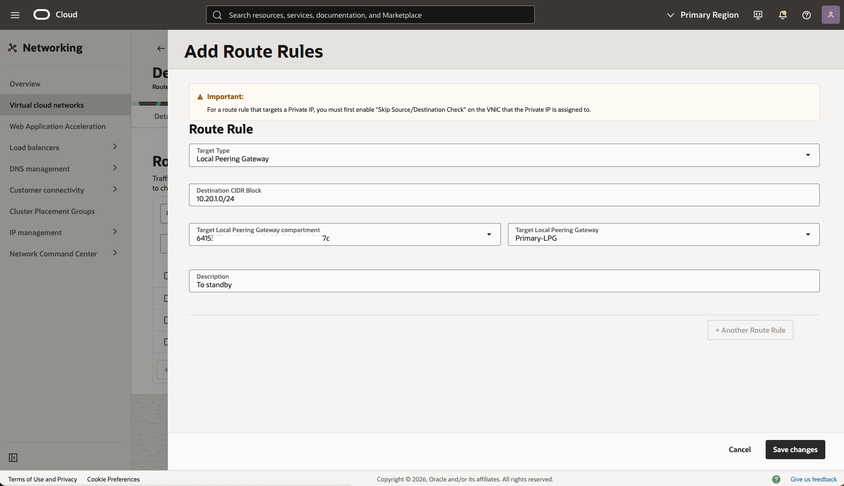
- Route Rule: Local Peering Gateway
- Destination CIDR Block: Enter your standby CIDR block. For example,
10.20.1.0/24 - Target Local Peering Gateway Compartment: Select the compartment that you created the local peering gateway in the previous step.
- Target Local Peering Gateway: Select your Local Peering Gateway.
- Description: Enter a description for this Route rule.
- Select the Add Route Rules button.
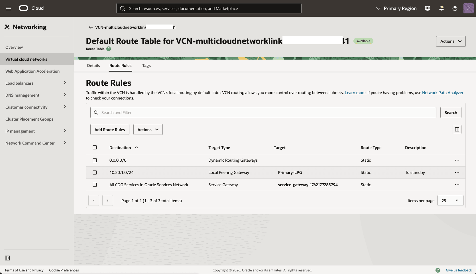
- In the primary Virtual Cloud Networks detail page, select the Routing tab, select the name of your default route table.
Configure the Network in the Standby Zone
Configure the network in the standby availability zone by using the following steps:
- From the OCI console select the name of your standby VM Cluster, Scroll down to the Network section, and then select the standby Virtual cloud network link.
- Create Local Peering Gateway
Standby-LPGin Virtual Cloud Network.- In the Virtual Cloud Networks detail page, select the Gateways tab.
- Scroll down to the Local Peering Gateways section, and then select the Create Local Peering Gateway button.
- Choose a name, for example,
Standby-LPG, and then select the Create Local Peering Gateway button. - The Advanced options section is optional.
- Select the Create Local Peering Gateway button.
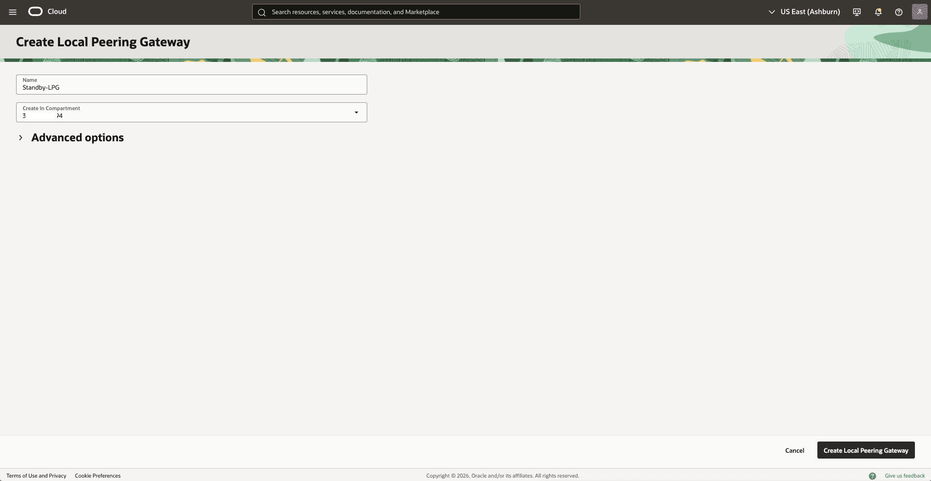
- Choose a name, for example,
- Establish a peering connection between the Standby LPG and the primary LPG OCID.
- In the Local Peering Gateways section, identify the LPG created in the previous step, select the three dots, then select the Establish Peering Connection option.
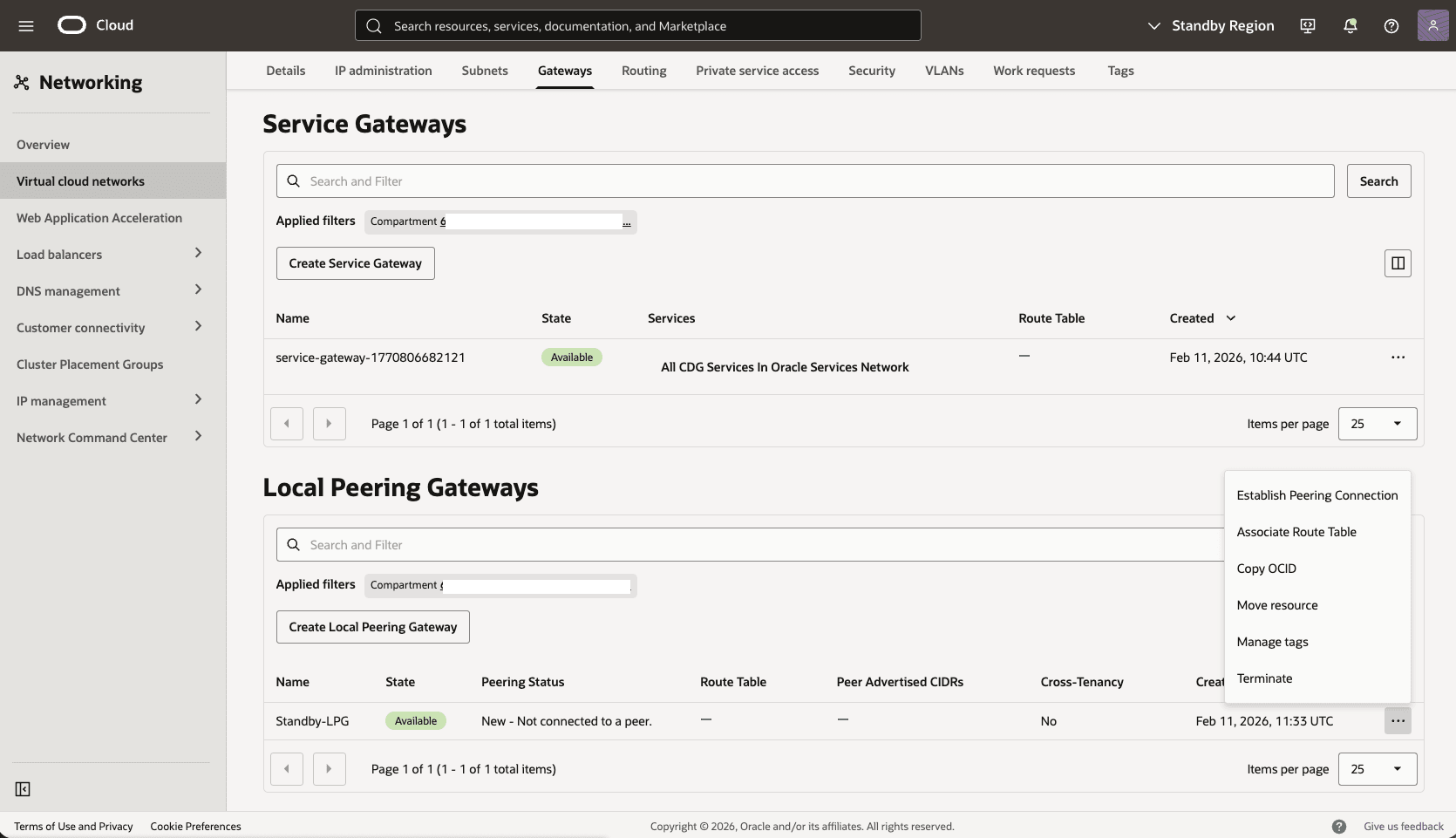
- Select the Enter Local Peering Gateway OCID option, paste the Primary LPG OCID that you copied in the previous step, and then select the Establish Peering Connection button.
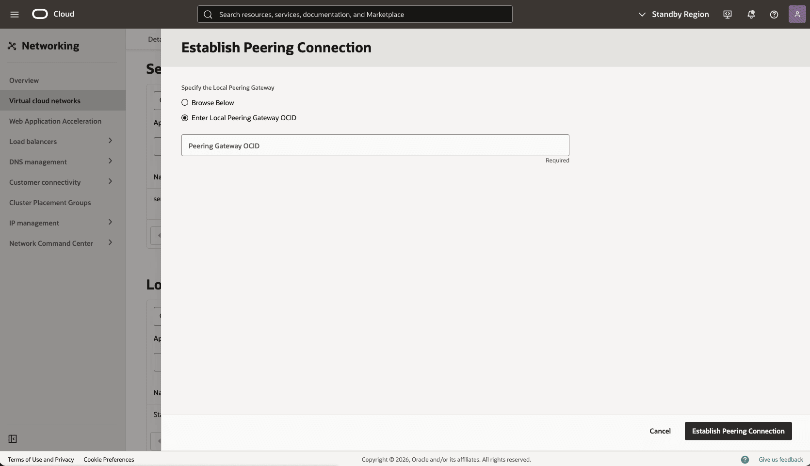
- In the Local Peering Gateways section, identify the LPG created in the previous step, select the three dots, then select the Establish Peering Connection option.
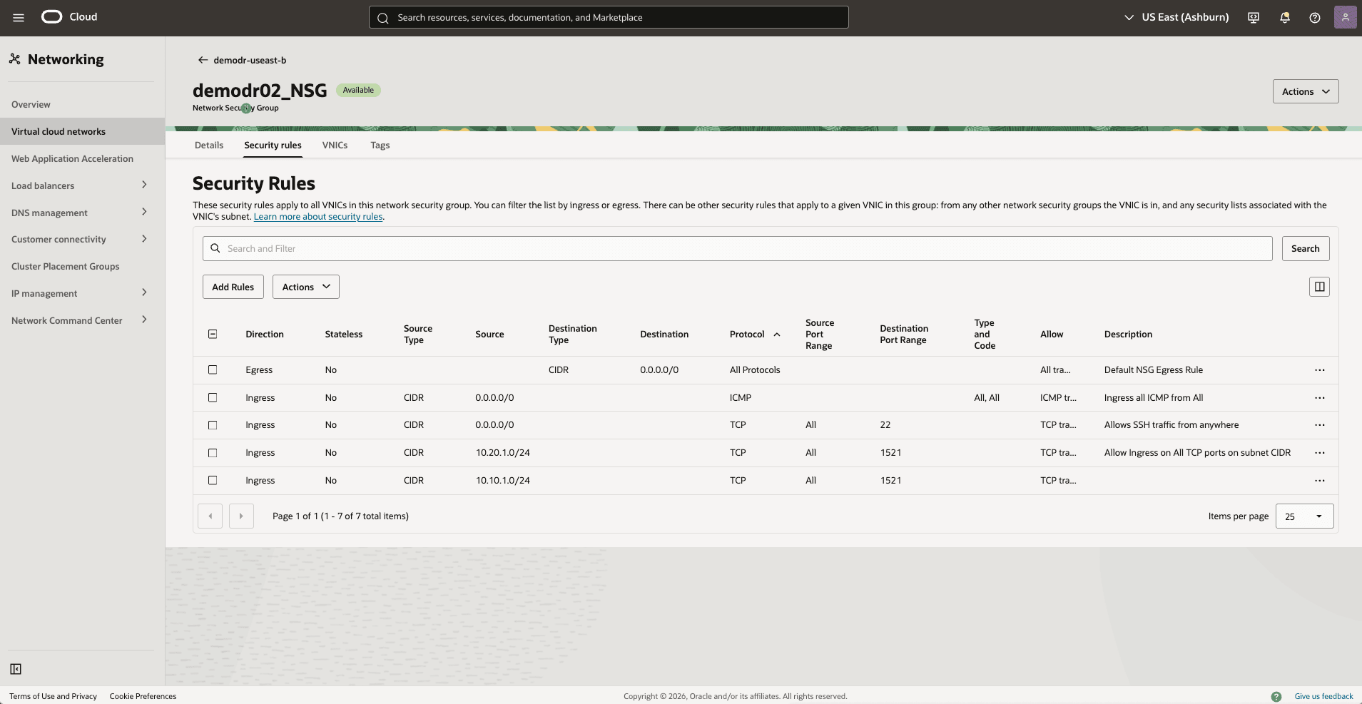
- Update the OCI network security group for your standby VM cluster to allow traffic from the primary network.
- In the standby Virtual Cloud Networks detail page, select the Security tab, scroll down to the Network Security Groups section, and then select the name of your VM Cluster Network Security Groups.
- Select the Security rulestab, and select the Add Rules button, and then create a rule with the following specifications.
- Direction: Ingress
- Source Type: CIDR
- Source CIDR: enter your stand by CIDR block. For example:
10.10.1.0/24. - IP Protocol: TCP
- Source Port Range: Empty (All)
- Destination Port Range: 1521
- Description: Enter a description for this rule.
- Select the Add button.
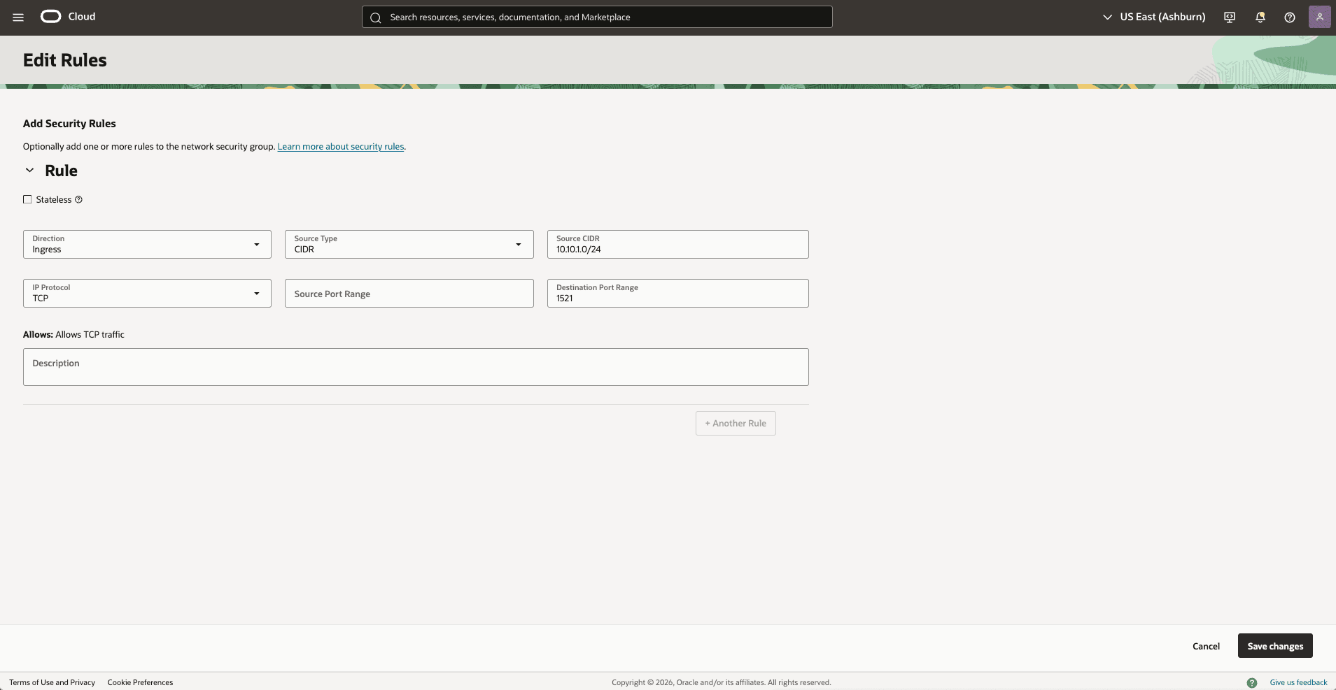
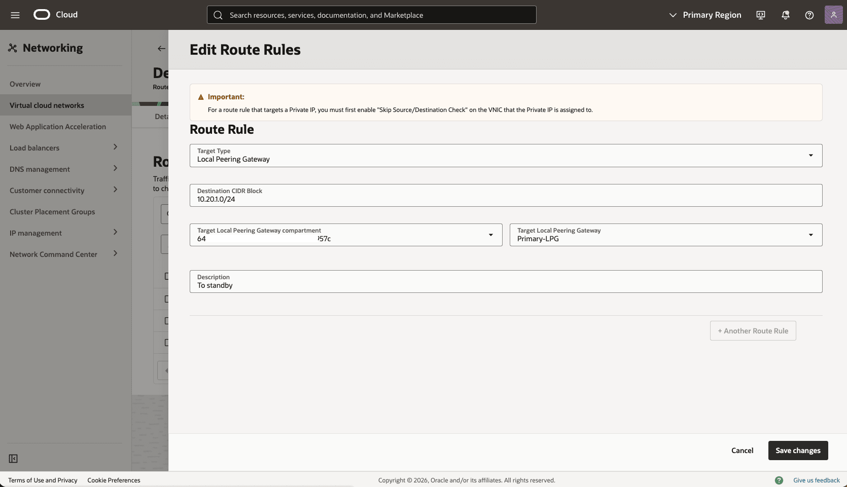
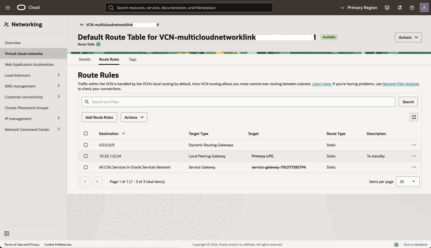
- Add a route rule to the default route table in the standby VCN to route primary traffic to Stanby-LPG.
- In the Standby Virtual Cloud Networks detail page, select the Routing tab, and then select the name of your default route table.
- Select the Route Rules tab, and then select the Add Route Rules button.
- Route Rule: Local Peering Gateway
- Destination CIDR Block: Enter your stand by CIDR block. For example:
10.10.1.0/24. - Target Local Peering Gateway Compartment: Select the compartment where you created the local peering gateway in the previous step
- Target Local Peering Gateway: Select your Local Peering Gateway
- Description: Enter a description for this Route rule
- Select the Add Route Rules button.
Test Connectivity
- Test connectivity from Primary to Standby and Standby to Primary. You can use ping or SSH if you add SSH access to the applicable network security group.
- For configuring Data Guard, see the next section.
There is currently no content for this page. Oracle AI Database@Azure team intends to add content here, and this placeholder text is provided until that text is added.
The Oracle AI Database@Azure team is excited about future new features, enhancements, and fixes to this product and this accompanying documentation. We strongly recommend you watch this page for those updates.
Connectivity by Azure Network
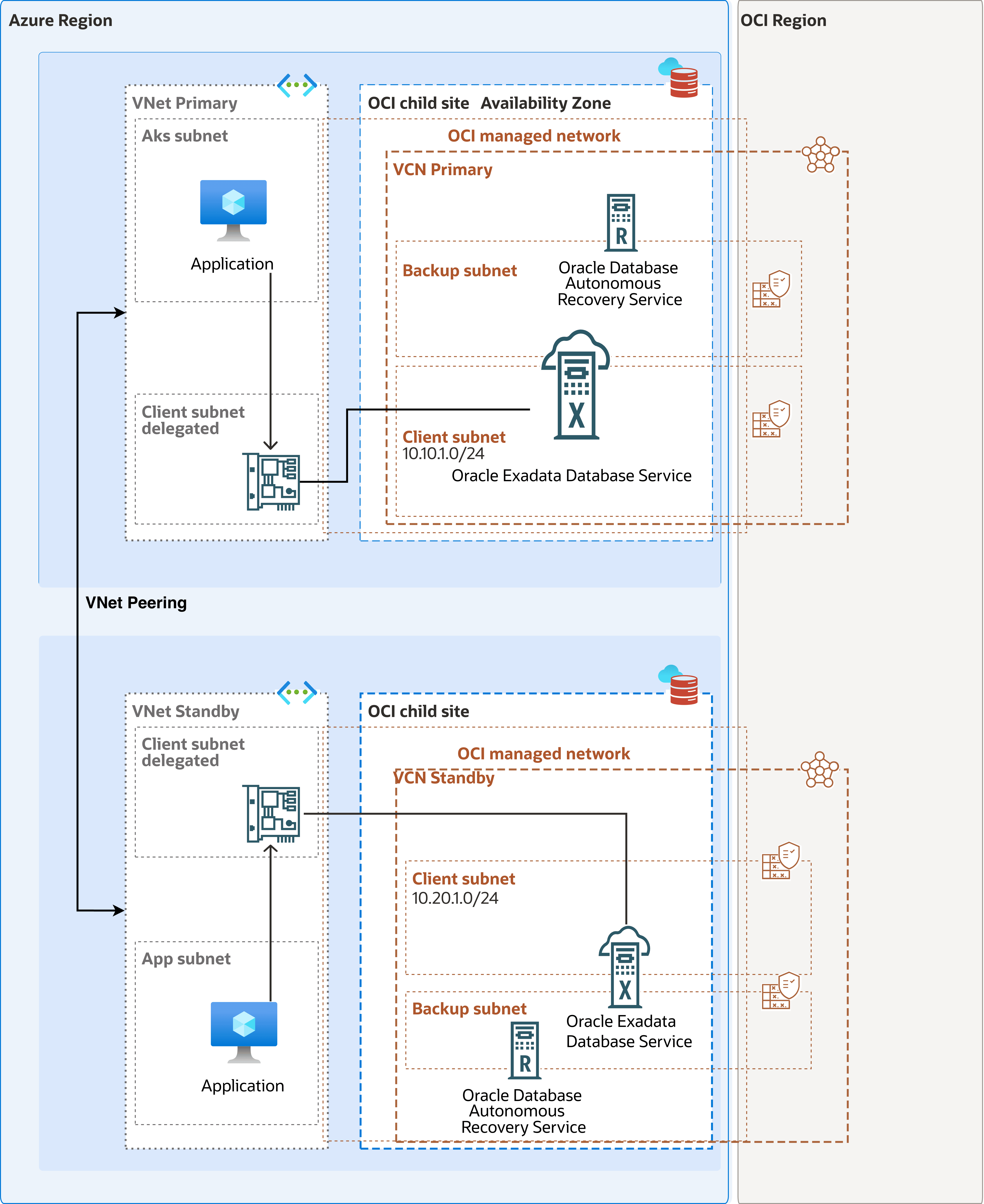
Configure the network for Oracle Data Guard between two Oracle AI Database@Azure deployments in the same Azure region and in different availability zones. This architecture uses Azure VNet peering between two Azure virtual networks (VNets). Each VNet contains one Oracle AI Database@Azure delegated subnet.
This procedure covers the Azure Portal configuration for cross-zone Data Guard network preparation:
- The deployments must be in the same Azure region.
- The deployments must be in two Azure availability zones.
- The configuration must use two Azure VNets.
- Each VNet contains one delegated subnet.
- The VNet address spaces must not overlap.
Note
- Direct VNet peering uses Azure system routes and avoids the additional latency, routing complexity, availability dependency, and throughput constraints associated with an Azure Firewall or NVA. Route Data Guard traffic through a firewall or NVA only when inspection, compliance, or an established network security architecture requires it.
- Before you deploy Oracle AI Database@Azure resources, verify that Azure Advanced Networking (
EnableRotterdamSdnApplianceForOraclefeature) is enabled in the subscription.
The following diagram illustrates the architecture diagram for configuring cross-AZ by Azure network.
Configuration Instructions
The following table shows an example architecture. Replace the sample names and CIDR blocks with the values for your deployment.
Component Primary Standby Azure region US East US East Availability zone AZ1 AZ2 Resource group rg-odaa-primary rg-odaa-standby VNet vnet-odaa-primary vnet-odaa-standby VNet CIDR 10.10.0.0/16 10.20.0.0/16 Oracle delegated subnet snet-odaa-primary snet-odaa-standby Delegated subnet CIDR 10.10.1.0/24 10.20.1.0/24 Oracle Database role Primary Standby Data Guard traffic between the primary and standby database client subnets uses Azure VNet peering. The traffic path is bidirectional:- Primary DB client subnet 10.10.1.0/24
- Azure VNet peering
- Standby DB client subnet 10.20.1.0/24
- Standby DB client subnet 10.20.1.0/24
- Azure VNet peering
- Primary DB client subnet 10.10.1.0/24
Complete the following steps for configuration:- Create the VNet Peering
Complete the following steps to create VNet peering from the primary VNet to the standby VNet and from the standby VNet to the primary VNet. You can create the peering in both directions in the Azure Portal when you have permissions for both VNets.
- From the Azure Portal, navigate to Virtual networks.
- Select the VNet that you are using. For example: vnet-odaa-primary.
- From the left menu, expand the Settings section and then select Peerings.
- Select the + Add button to create a virtual network peering.
- From the Add peering page, complete the following steps:
- Enter a remote peering link name in the Peering link name field. The name must begin with a letter or number, end with a letter, number or underscore, and may contain only letters, numbers, underscores, periods, or hyphens. For example,
primary-to-standby. - Choose the Peering type as Virtual network.
- From the Subscription dropdown list, select the subscription that contains
vnet-odaa-standby. - Select your Virtual network. For example,
vnet-odaa-standby. - From the Remote virtual network peering settings section, configure remote peering settings.
- Allow the peered virtual network to access to your virtual network: This option is enabled by default. Select this option to allow traffic from the peered virtual network to your virtual network.
- Allow the peered virtual network to receive forwarded traffic from your network: Enabling this option will allow the peered virtual network to receive traffic from virtual networks peered to your virtual network.
- Allow gateway or route server in the peered virtual network to forward traffic to your virtual network: Enabling this setting will allow the VNet to receive traffic from the peered virtual networks' gateway or route server.
- Enable the peered virtual network to use your VNet's remote gateway or route server: This option can be enabled only if your VNet has a remote gateway or route server and VNet enables "Allow gateway in VNet to forward traffic to the peered virtual network". This option can be enabled in only one of the peered virtual networks' peerings.
- From the Local virtual network summary section, enter a peering link name. For example,
standby-to-primary. The name must begin with a letter or number, end with a letter, number or underscore, and may contain only letters, numbers, underscores, periods, or hyphens. - From the Local virtual network peering settings section, complete the following steps:
- Allow this virtual network to access the peered virtual network: This option is enabled by default.
- Allow forwarded traffic from this virtual network: Leave this option disabled and the checkbox unselected unless a firewall or NVA forwards traffic.
- Enable gateway or route server traffic: Leave this option disabled unless you use gateway transit or Route Server.
- Review your information, and then select the Add button.
- Enter a remote peering link name in the Peering link name field. The name must begin with a letter or number, end with a letter, number or underscore, and may contain only letters, numbers, underscores, periods, or hyphens. For example,
- Verify Peering State
- From the Azure Portal, navigate to Virtual networks.
- Select the VNet that you are using. For example:
vnet-odaa-primary. - From the left menu, expand the Settings section and then select Peerings.
- Ensure that
primary-to-standbyshows Connected. - From the VNet list, select
vnet-odaa-standby. - From the left menu, expand the Settings section, and then select Peerings.
- Ensure that
standby-to-primaryshows Connected.
- Configure Azure and OCI Security Rules
Configure Azure network security groups (NSGs) if NSGs are enabled for the delegated subnet deployment. Then, configure matching OCI network security group or security list rules for the OCI database network. The Azure and OCI rules must allow the same primary-to-standby and standby-to-primary listener traffic.
- Azure Primary Delegated Subnet NSG
- Create an inbound rule by using the following value:
Field Value Source 10.20.1.0/24 Source port ranges * Destination 10.10.1.0/24 or Any Service Custom Destination port ranges 1521 Protocol TCP Action Allow Priority Use a priority before deny rules Name allow-dg-from-standby - Create an outbound rule by using the following values:
Field Value Source 10.10.1.0/24 or Any Source port ranges * Destination 10.20.1.0/24 Service Custom Destination port ranges 1521 Protocol TCP Action Allow Priority Use a priority before deny rules Name allow-dg-to-standby
- Create an inbound rule by using the following value:
- Azure Standby Delegated Subnet NSG
- Create an inbound rule by using the following value:
Field Value Source 10.10.1.0/24 Source port ranges * Destination 10.20.1.0/24 or Any Service Custom Destination port ranges 1521 Protocol TCP Action Allow Priority Use a priority before deny rules Name allow-dg-from-primary - Create an outbound rule by using the following values:
Field Value Source 10.20.1.0/24 or Any Source port ranges * Destination 10.10.1.0/24 Service Custom Destination port ranges 1521 Protocol TCP Action Allow Priority Use a priority before deny rules Name allow-dg-to-primary
- Create an inbound rule by using the following value:
- OCI Network Security Rules
From the Oracle AI Database@Azure resources, navigate to the Go to OCI link to open the primary and standby database in the OCI Console. Identify the VCN, database client subnet, and network security group (NSG) that each database network uses. Add the required rules to the NSG attached to each database network.
Use stateful rules unless your environment requires stateless rules. If you use stateless rules, add the corresponding return-path rules for the ephemeral response ports that your security design requires.
- OCI Primary Database Network NSG
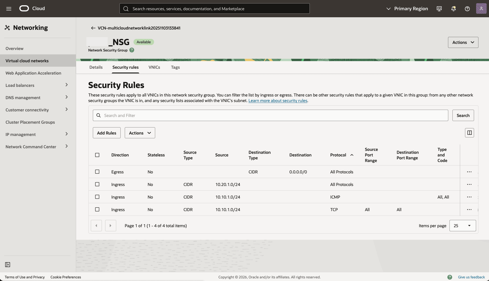
- Create an ingress rule by using the following values:
Field Value Direction Ingress Source type CIDR Source CIDR 10.20.1.0/24 IP protocol TCP Source port range All Destination port range 1521 Stateless No Description allow-dg-from-standby - Create an egress rule by using the following values:
Field Value Direction Egress Destination type CIDR Destination CIDR 10.20.1.0/24 IP protocol TCP Source port range All Destination port range 1521 Stateless No Description allow-dg-to-standby
- Create an ingress rule by using the following values:
- OCI Standby Database Network NSG
- Create an ingress rule by using the following values:
Field Value Direction Ingress Source type CIDR Source CIDR 10.10.1.0/24 IP protocol TCP Source port range All Destination port range 1521 Stateless No Description allow-dg-from-primary - Create an egress rule by using the following values:
Field Value Direction EgressDestination type CIDRDestination CIDR 10.10.1.0/24IP protocol TCPSource port range AllDestination port range 1521Stateless NoDescription allow-dg-to-primary
- Create an ingress rule by using the following values:
- OCI Primary Database Network NSG
If the database uses TCPS or custom listener ports, add separate rules for those ports. Common TCPS deployments use TCP port
2484.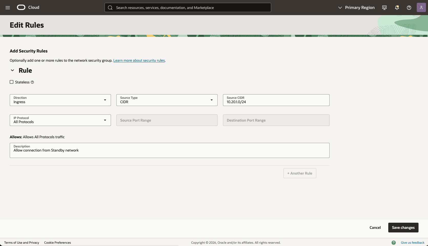
- Azure Primary Delegated Subnet NSG
- Test Connectivity
- Test connectivity from the Primary database to the Standby database and from the Standby database to the Primary database. You can use ping or SSH if you configure SSH access in the applicable network security group.
- To configure Oracle Data Guard, see the next sections.
There is currently no content for this page. Oracle AI Database@Azure team intends to add content here, and this placeholder text is provided until that text is added.
The Oracle AI Database@Azure team is excited about future new features, enhancements, and fixes to this product and this accompanying documentation. We strongly recommend you watch this page for those updates.
Cross-Region
This section guides you through the complete setup of the network configuration to establish data replication by using either an OCI network or a Azure network across regions.
Connectivity by OCI Network
The following diagram illustrates this architecture for configuring cross-region by OCI network.
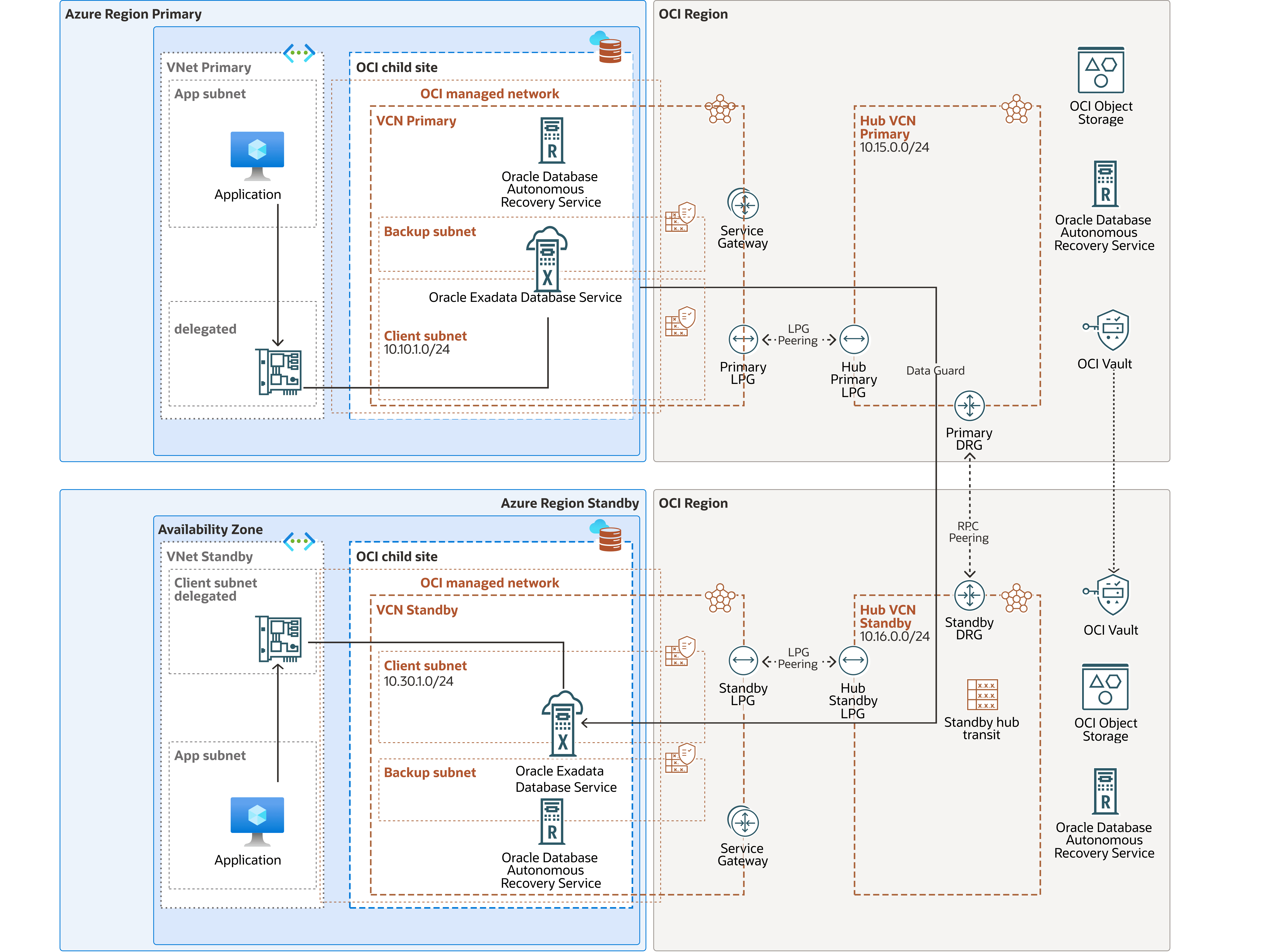
This architecture directs primary-to-standby network traffic through the OCI network to improve network throughput. OCI creates the VCNs automatically after Oracle AI Database@Azure creates the deployments for the primary and standby databases.
In this architecture:- The primary Exadata VM Cluster is deployed in the primary region in Primary VCN and the client subnet CIDR
10.10.1.0/24. - Primary Hub VCN
10.15.0.0/24. - The standby Exadata VM Cluster is deployed in the standby region in Standby VCN and the client subnet CIDR
10.30.1.0/24. - Standby Hub VCN
10.16.0.0/24.
Note
- Download the diagram and update the diagram with your CIDR values.
- Review the Remote Peering Connection Count service limit, and request a service limit increase if needed.
- Plan the hub VCN CIDR to avoid overlapping IP addresses. The hub VCN CIDR can be small, for example,
/28. - If you plan to deploy resources in the subnet, define the CIDR accordingly, for example, compute for Data Guard Far Sync.
To configure cross-region VCN peering and establish network communication between the regions that the architecture diagram shows, complete the following steps.
Configure the Network in the Primary Region
Configure the network in the Standby Region- From the OCI console, navigate to Networking, and create a Virtual Cloud Network (VCN) of the primary region (HUB VCN Primary).
- From the OCI console, select Networking, and then select Virtual cloud networks.
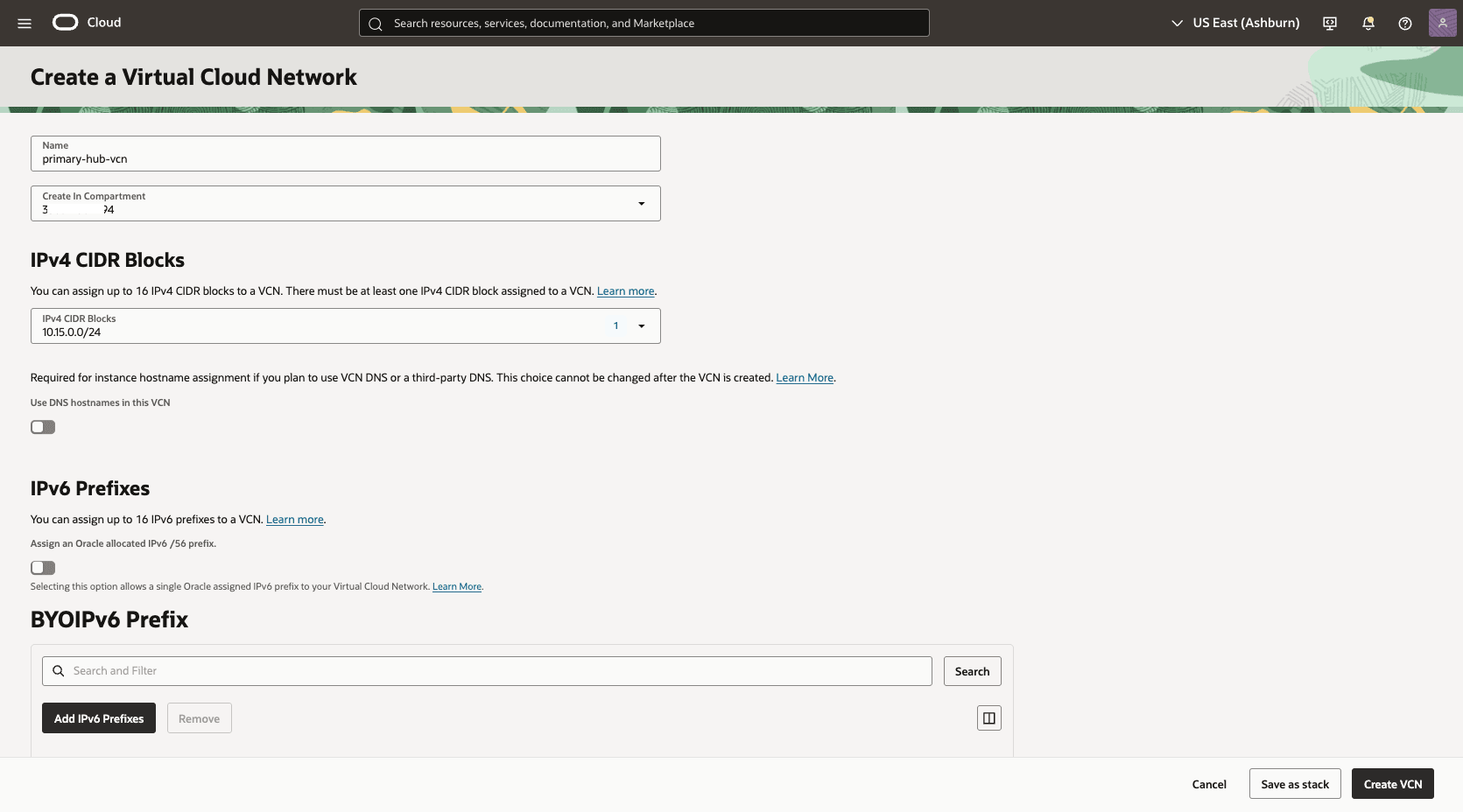
- Select Create VCN button, and enter the following information.
- Name: Enter a descriptive name. For example,
primary-hub-vcn. - Create in compartment: Select the compartment where you want to create the VCN.
- IPv4 CIDR Blocks: Enter the CIDR block for your Hub VCN. Ensure that this block does not overlap with your existing network address space.
- Select the Create VCN button.
- Name: Enter a descriptive name. For example,
- Deploy two local peering gateways (LPGs),
Primary-Hub-LPGandPrimary-LPG, in the primary hub VCN and the primary VCN, respectively.- In the Primary-Hub VCN detail page, select the Gateways tab, scroll down to the Local Peering Gateways section, and then select the Create Local Peering Gateway button.
- Choose a name. For example:
primary-hub-lpg.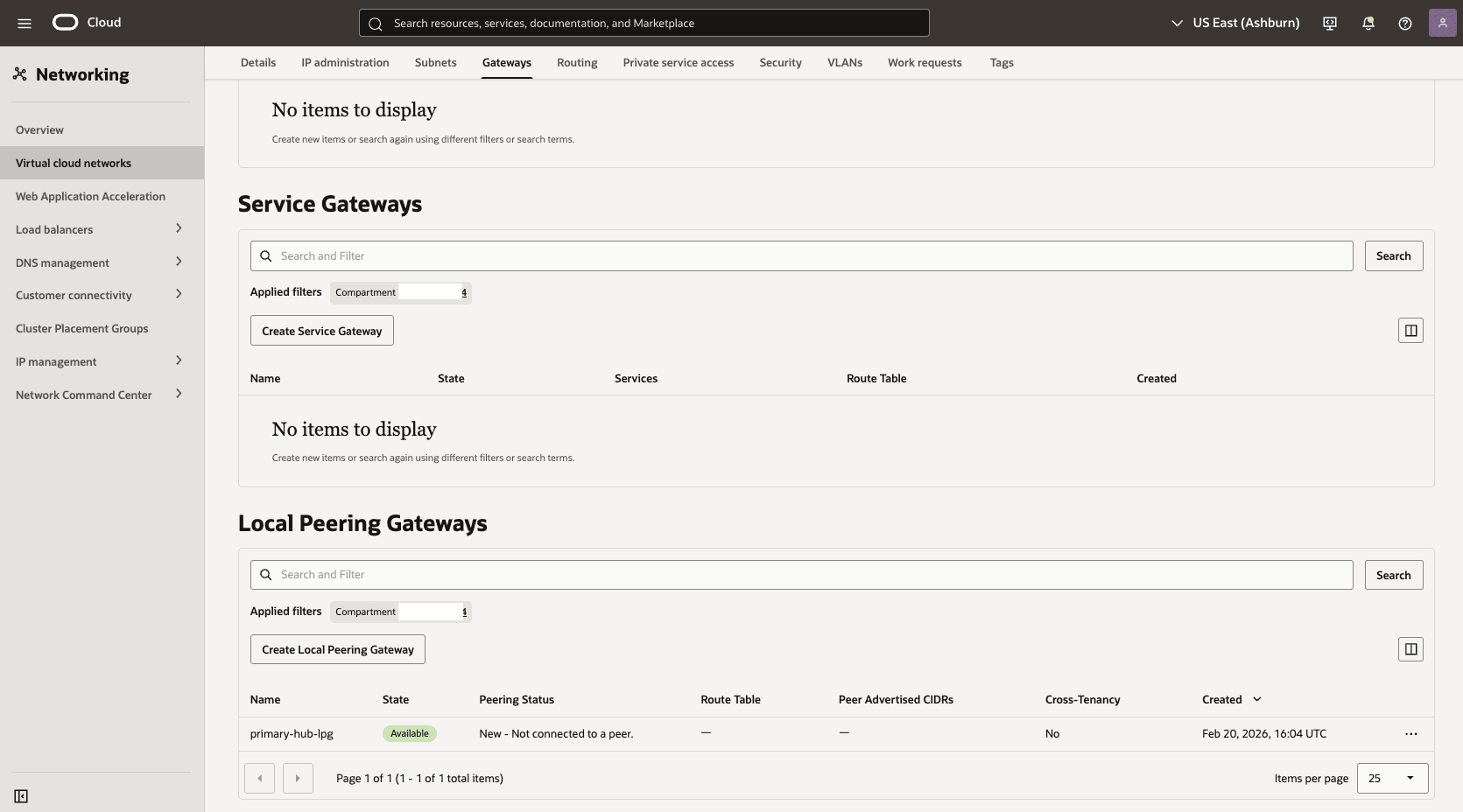
- Select the Create Local Peering Gateway button.
- In the Primary-Hub VCN detail page, select the Gateways tab, scroll down to the Local Peering Gateways section, and then select the Create Local Peering Gateway button.
- Choose a name. For example:
primary-lpg. - Select the Create Local Peering Gateway button.
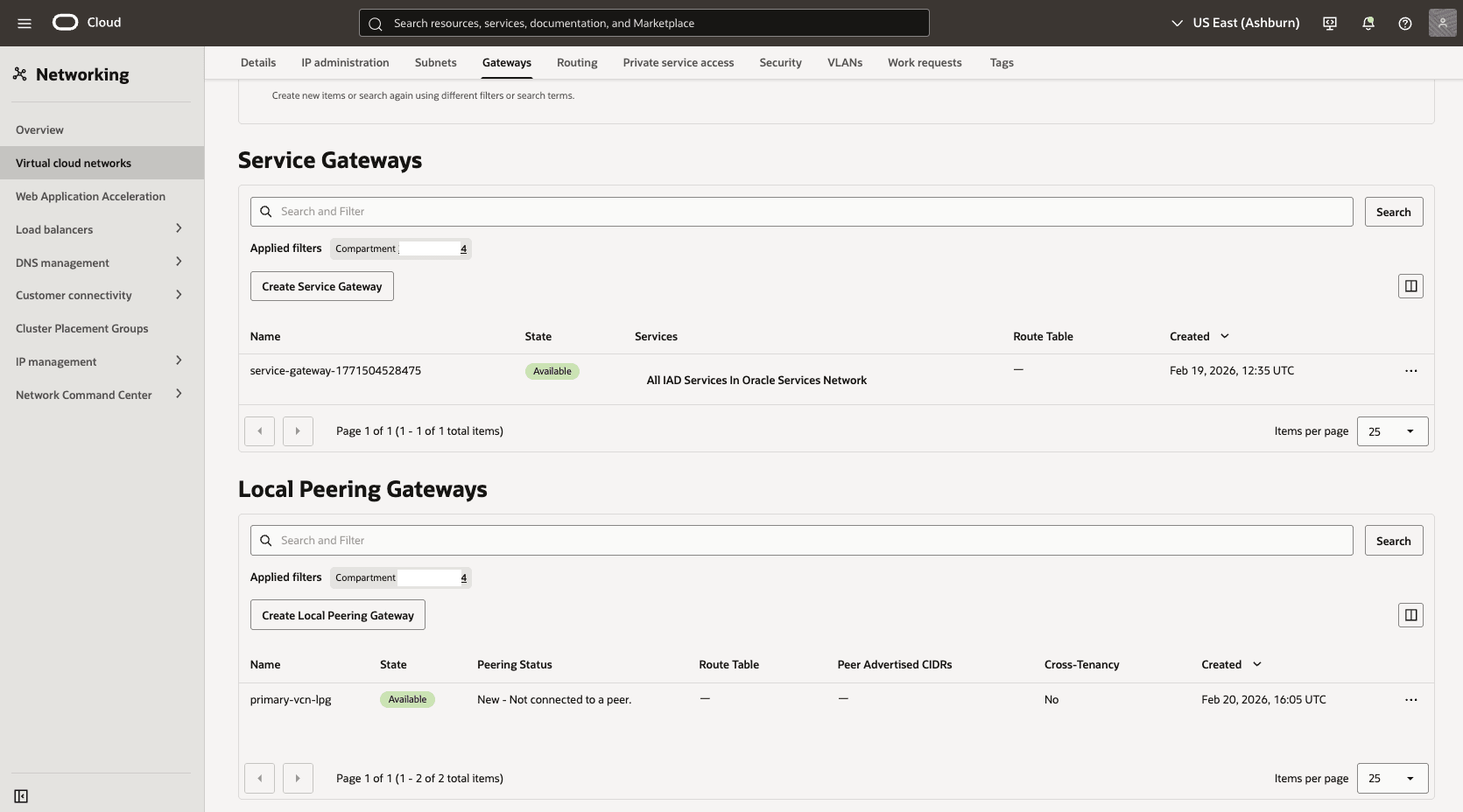
- Establish an LPG peering connection between the LPGs in the primary hub VCN and the primary VCN.
- In your Primary VM Cluster VCN, select the Gateways tab and select Local Peering Gateways. Locate the LPG that you created in the previous step. Select the three dots, and then select Establish Peering Connection option.
- From the Establish Peering Connection page, choose the Browse Below option, select the HUB VCN Primary, select the Primary-Hub-LPG, and then select the Establish Peering Connection button.
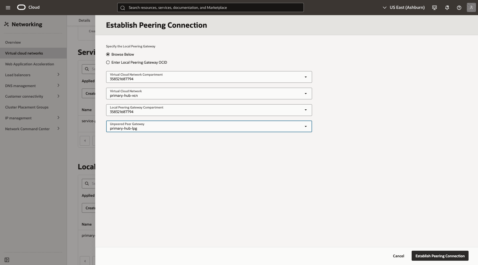
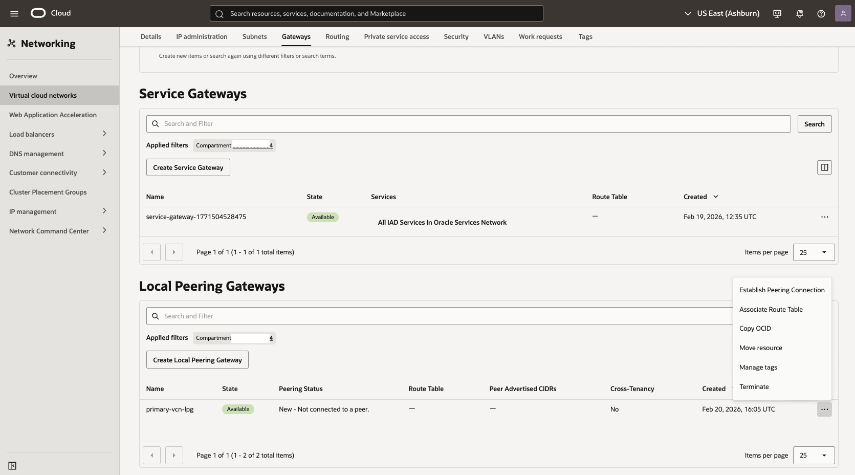
- In your Primary VM Cluster VCN, select the Gateways tab and select Local Peering Gateways. Locate the LPG that you created in the previous step. Select the three dots, and then select Establish Peering Connection option.
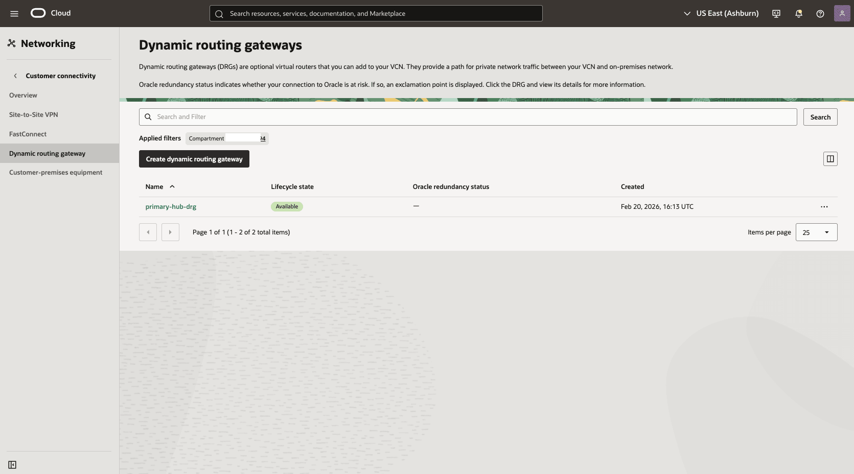
- Create a dynamic routing gateway (DRG) named
Primary-hub-drg.- From the OCI console, select Networking. Under the Customer connectivity section, select Dynamic routing gateway, and then select Create dynamic routing gateway button.
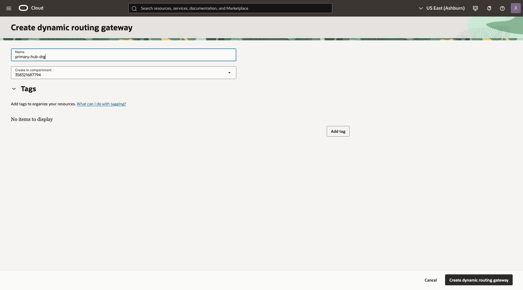
- Choose a name. For example,
Primary-hub-drg.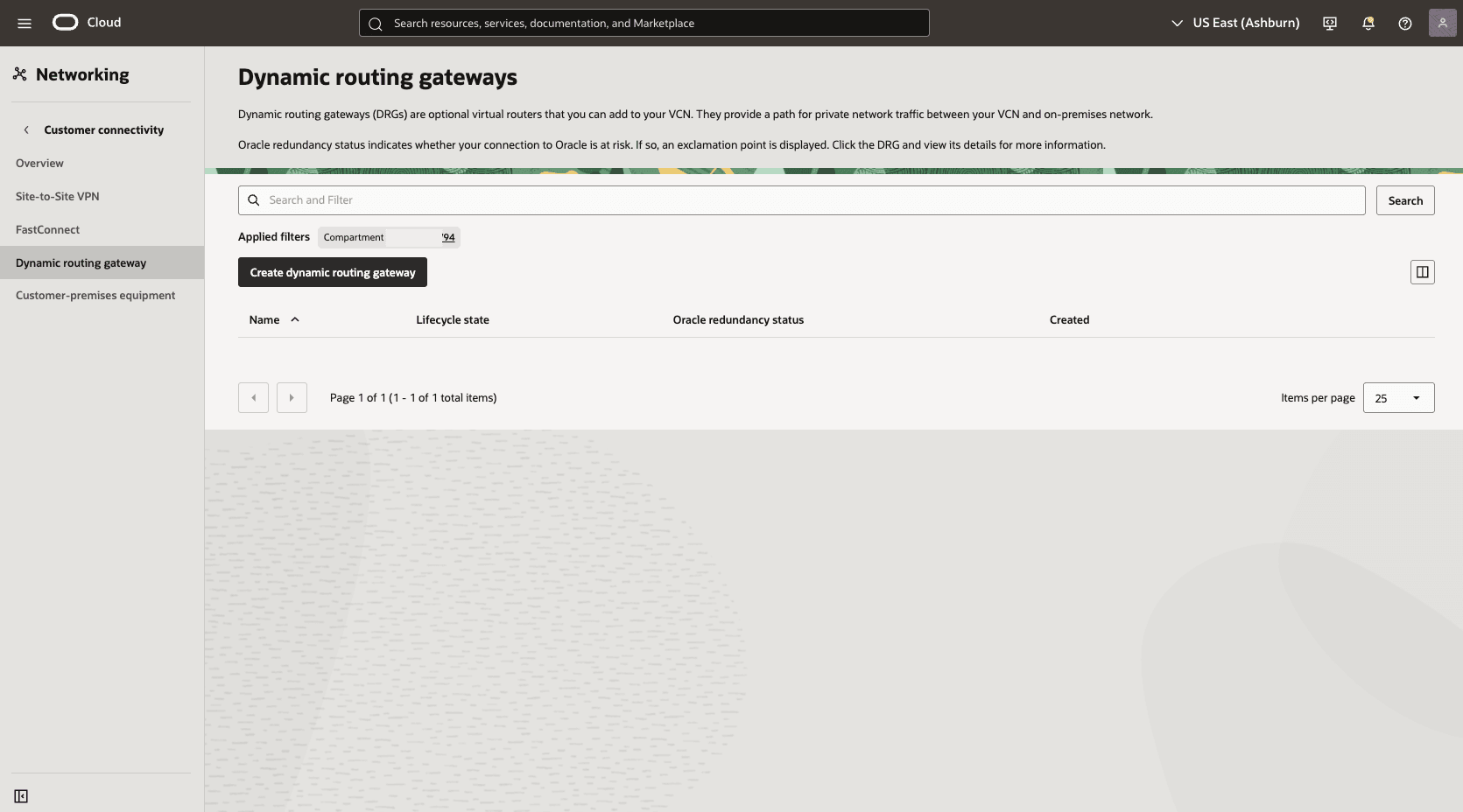
- Select the Create dynamic routing gateway button.
- Choose a name. For example,
- From the OCI console, select Networking. Under the Customer connectivity section, select Dynamic routing gateway, and then select Create dynamic routing gateway button.
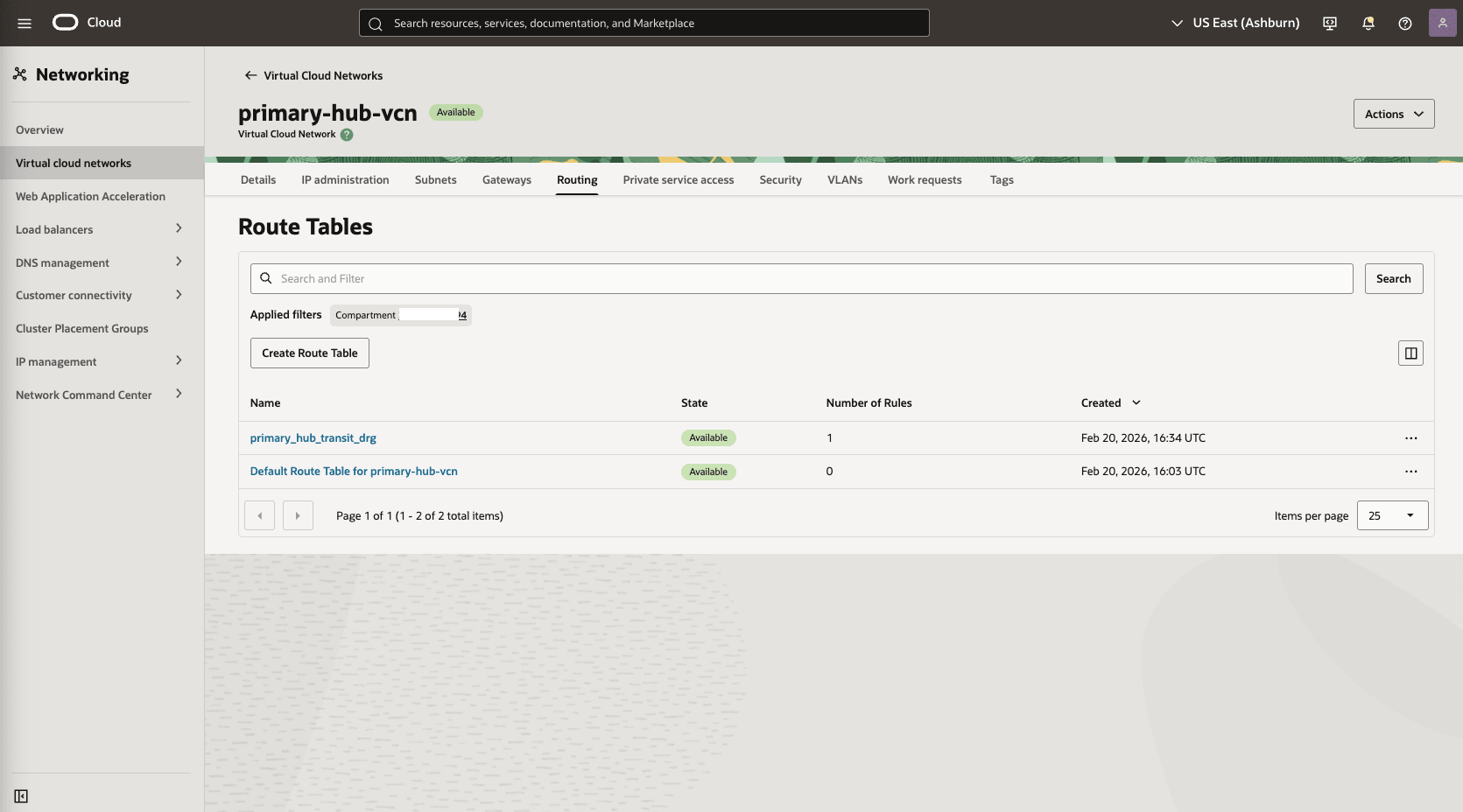
- Create a route table in the primary hub VCN to route network traffic between the primary hub VCN and the primary VCN.
- From the OCI console, select Networking, select Virtual cloud networks, and then select the HUB VCN Primary VCN.
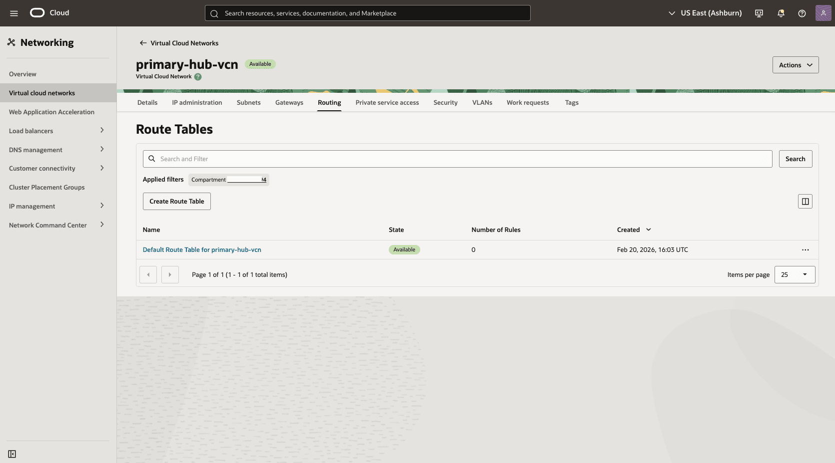
- Select the Routing tab, and then select the Create Route Tablebutton.
- Name: Choose a name. For example,
primary_hub_transit_drg. - Select the + Another Route Rule button.
- Target Type: Local Peering Gateway
- Destination CIDR Block: Enter 10.10.1.0/24 in the Primary VM Cluster Client Subnet CIDR field.
- Target Local Peering Gateway: Select the LPG of the created in the HUB VCN Primary. For example,
primary-hub-lpg. - Description: To primary client subnet.
- Select the Create button.

- Name: Choose a name. For example,
- From the OCI console, select Networking, select Virtual cloud networks, and then select the HUB VCN Primary VCN.
- Attach the DRG to the primary hub VCN.
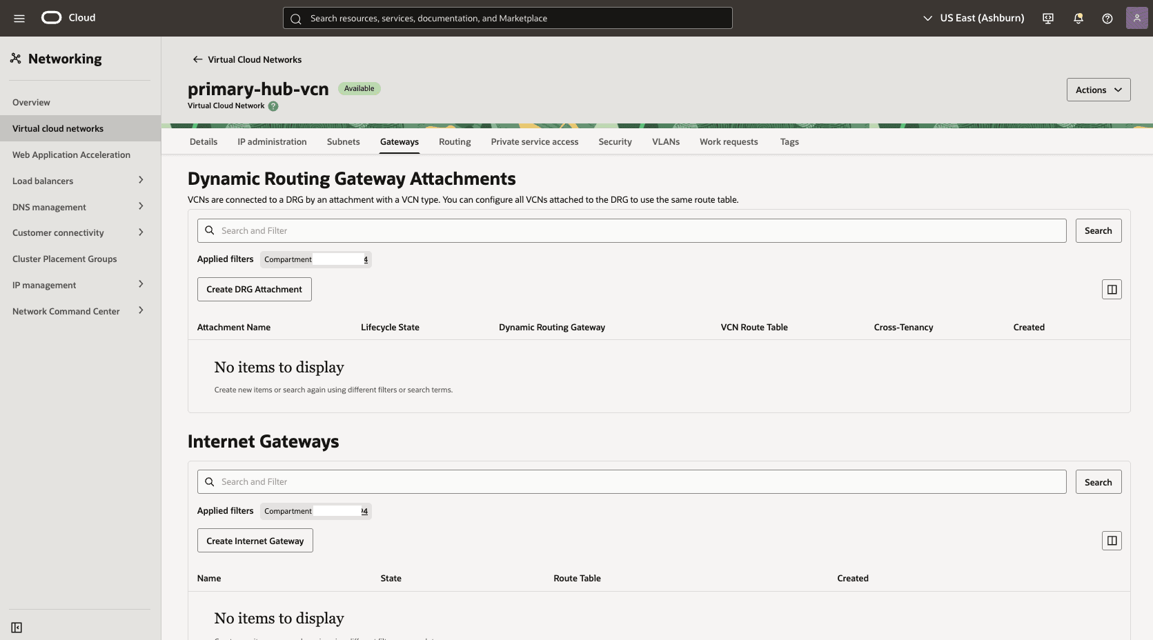
- In the Hub VCN Primary VCN section, select the Gateways tab. Under the Dynamic Routing Gateway Attachments section, select the Create DRG Attachment button.
- Name: Select a name. For example,
primary-hub-drg. - DRG Location: Select the current tenancy.
- Choose a DRG: Select the DRG name that you created in the previous step.
- The Advanced Options section is optional.
- Select the Select Existing option, then select the Routing Table that you created in the previous step. For example,
primary_hub_transit_drg.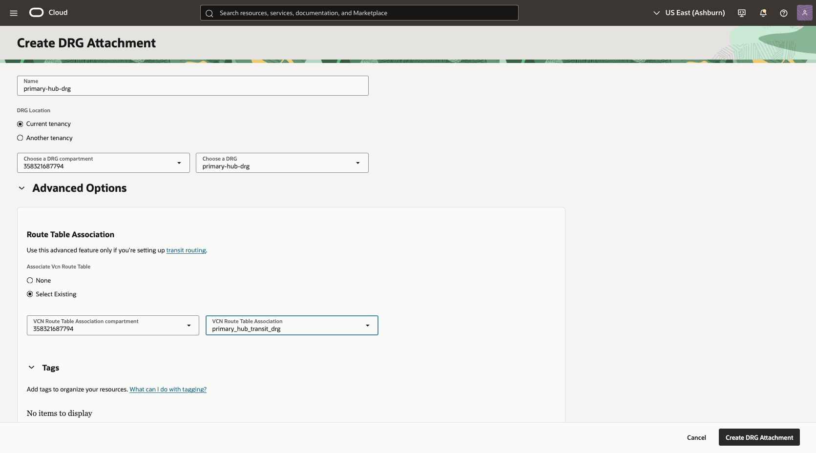
- Select the Create DRG Attachment button.
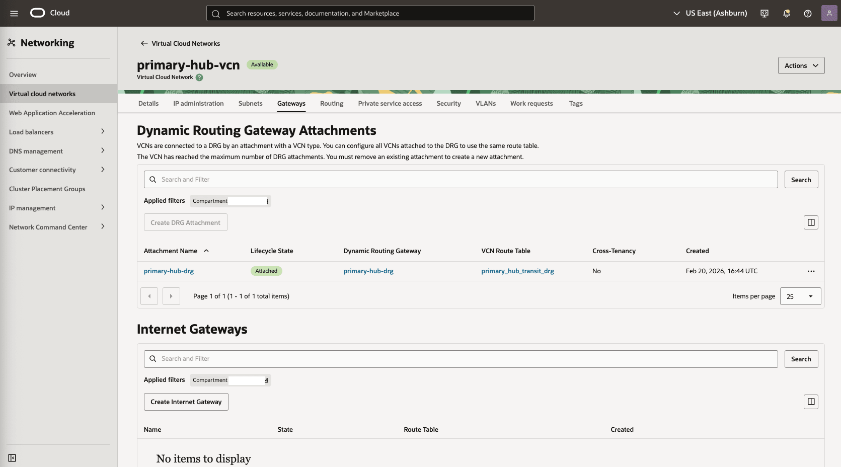
- In the Hub VCN Primary VCN section, select the Gateways tab. Under the Dynamic Routing Gateway Attachments section, select the Create DRG Attachment button.
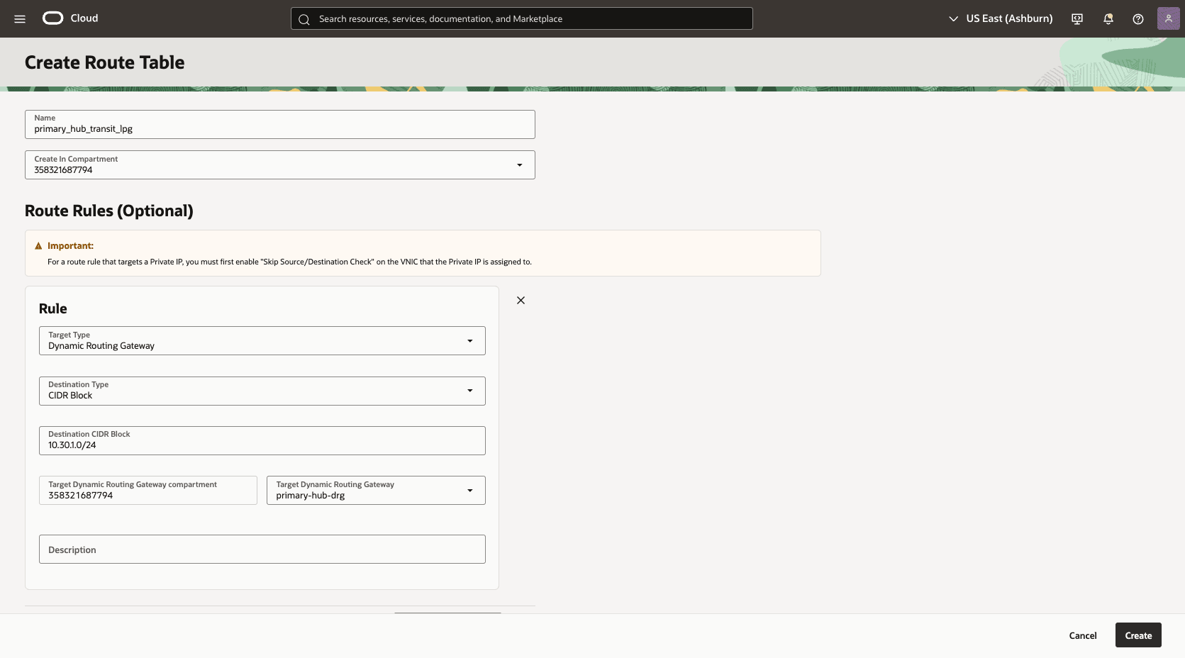
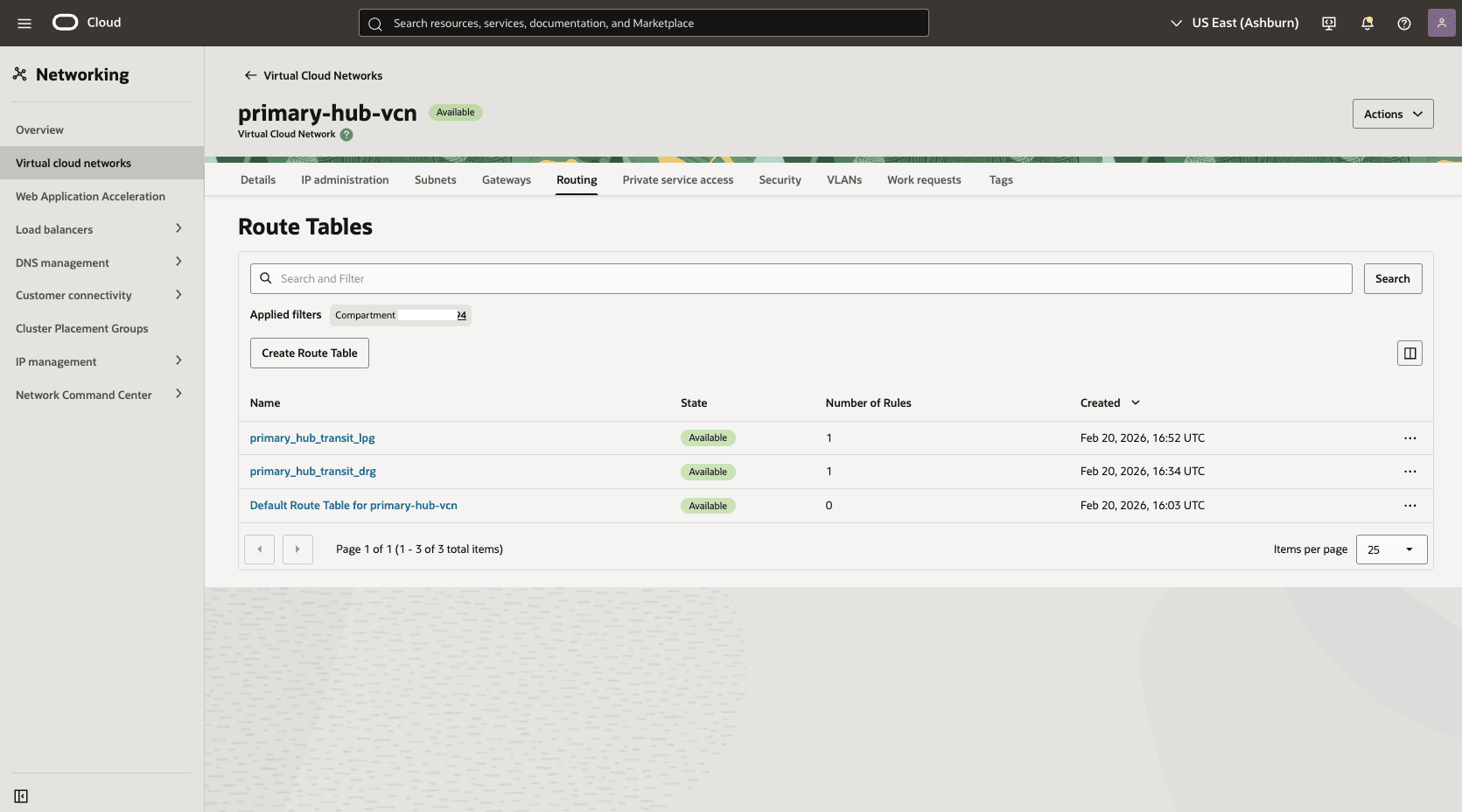
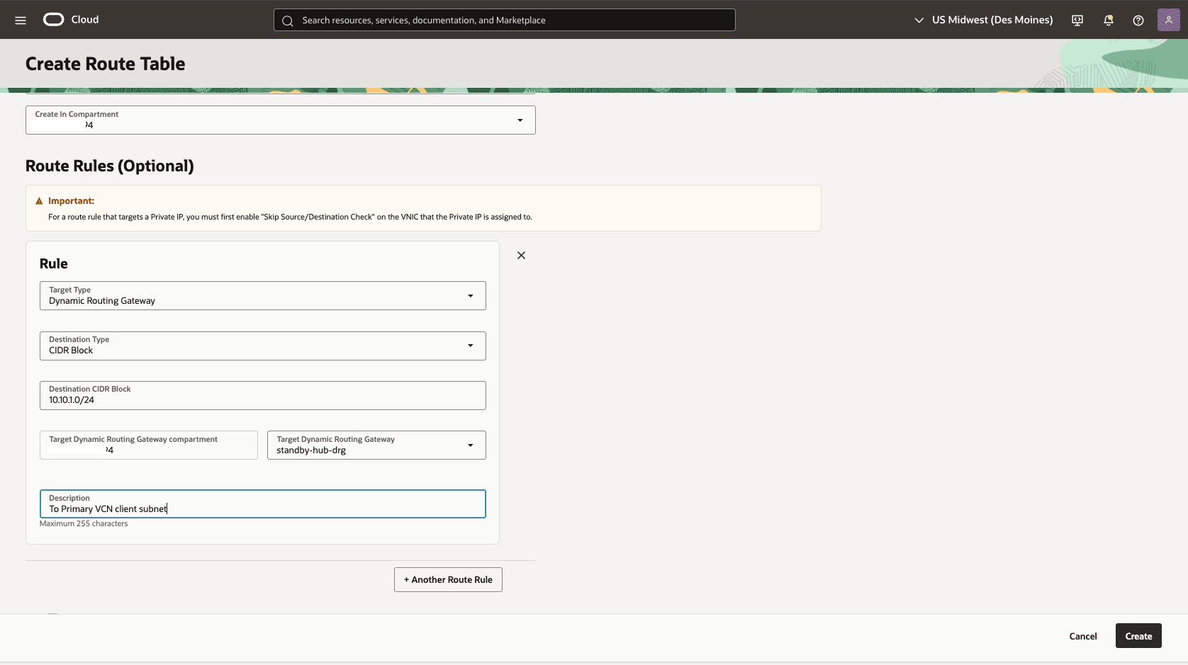
- In the primary hub VCN, create a second route table to direct network traffic to the standby network.
- From the HUB VCN Primary VCN, select the Routing tab, then select the Create Route Table button.
- Name: Choose a name. For example,
primary_hub_transit_lpg. - Select the + Another Route Rule button.
- Target Type: Dynamic Routing Gateway
- Destination CIDR Block: Enter the VCN Standby client subnet CIDR. For example,
10.30.1.0/24. - Target Dynamic Routing Gateway: Select the DRG associated with the HUB VCN Primary For example,
primary-hub-drg. - Description: To standby client subnet.
- Select the Create button.
- Associate the
primary_hub_transit_lpgroute table to theHub-Primary-LPGgateway.- From the Hub VCN Primary VCN, select the Gateways tab, scroll down to the Local Peering Gateways section.
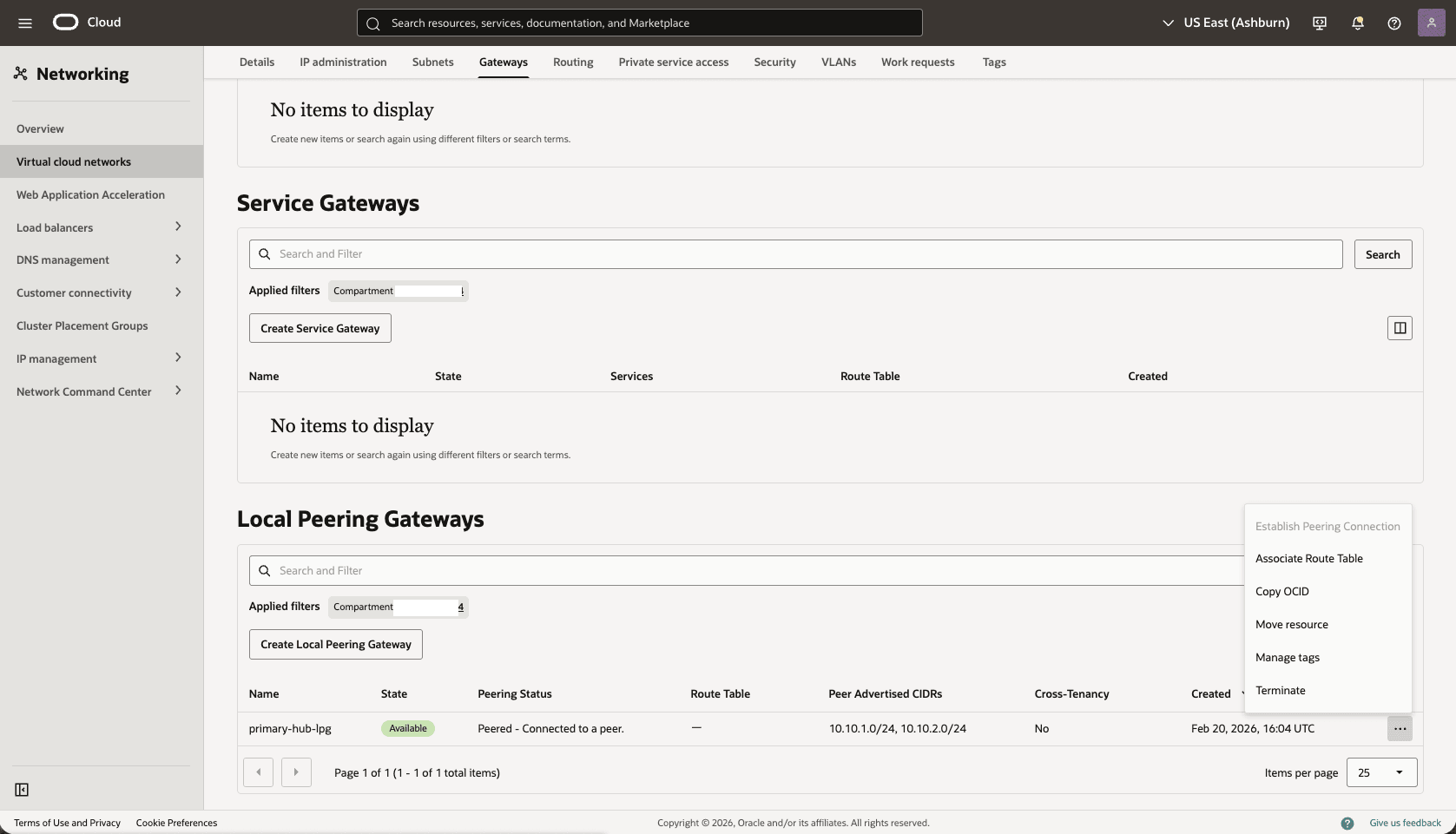
- Select the three dots, then select the Associate Route Table option.
- Select the route table that you created for the Local Peering Gateway. For example,
primary_hub_transit_lpg.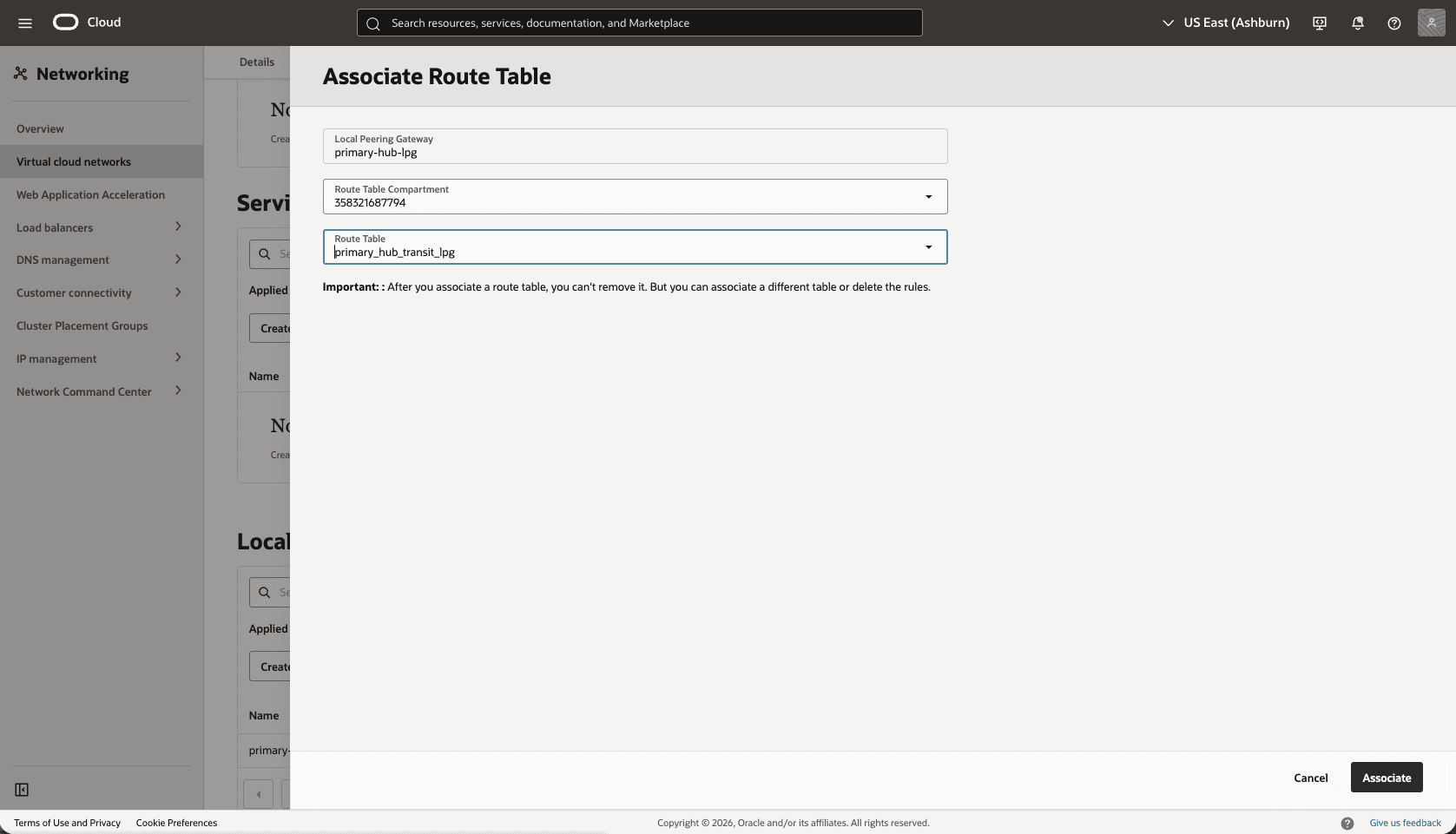
- Select the Associate button.
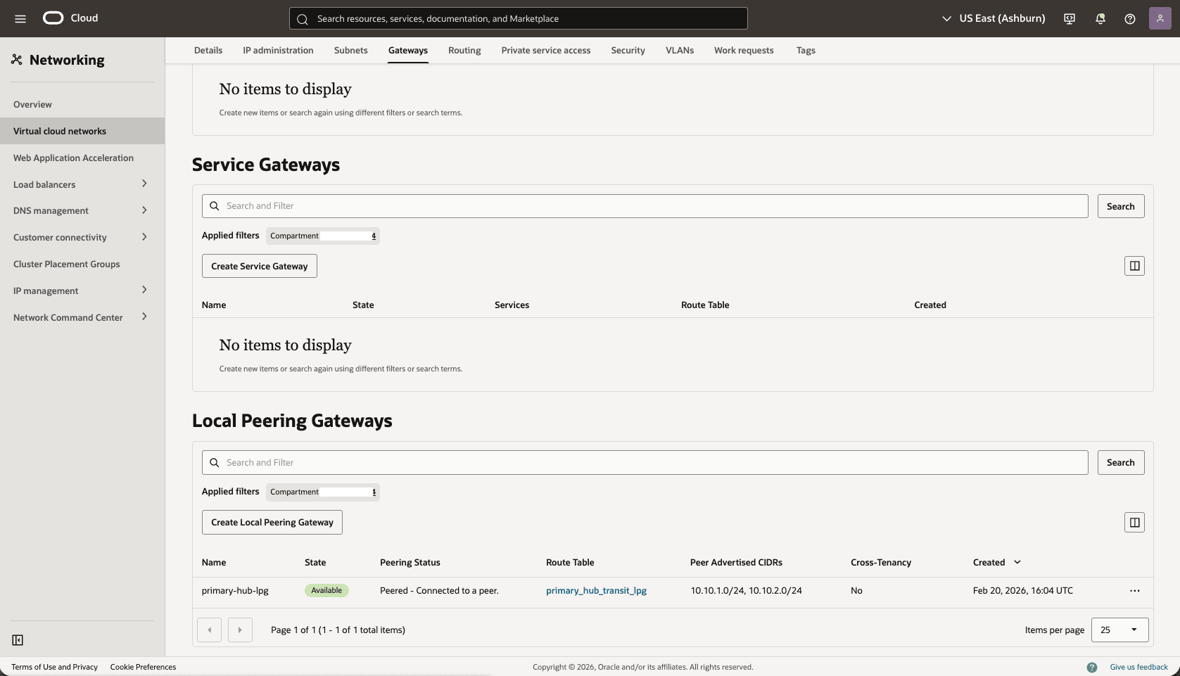
- From the Hub VCN Primary VCN, select the Gateways tab, scroll down to the Local Peering Gateways section.
- Edit the
Primary-Hub-DRGattachment from thePrimary-Hub-VCNto update theDRGroute table.- From the Hub VCN Primary VCN, select the Gateways tab. Under the Dynamic Routing Gateway Attachments section, select the name of your DRG attachment.
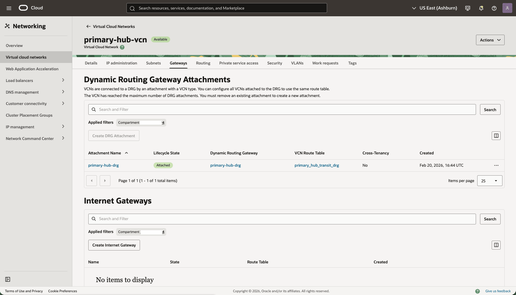
- Select the Edit button.
- In the DRG route table, select Autogenerated Drg Route Table for RPC, VC, and IPSec attachments.
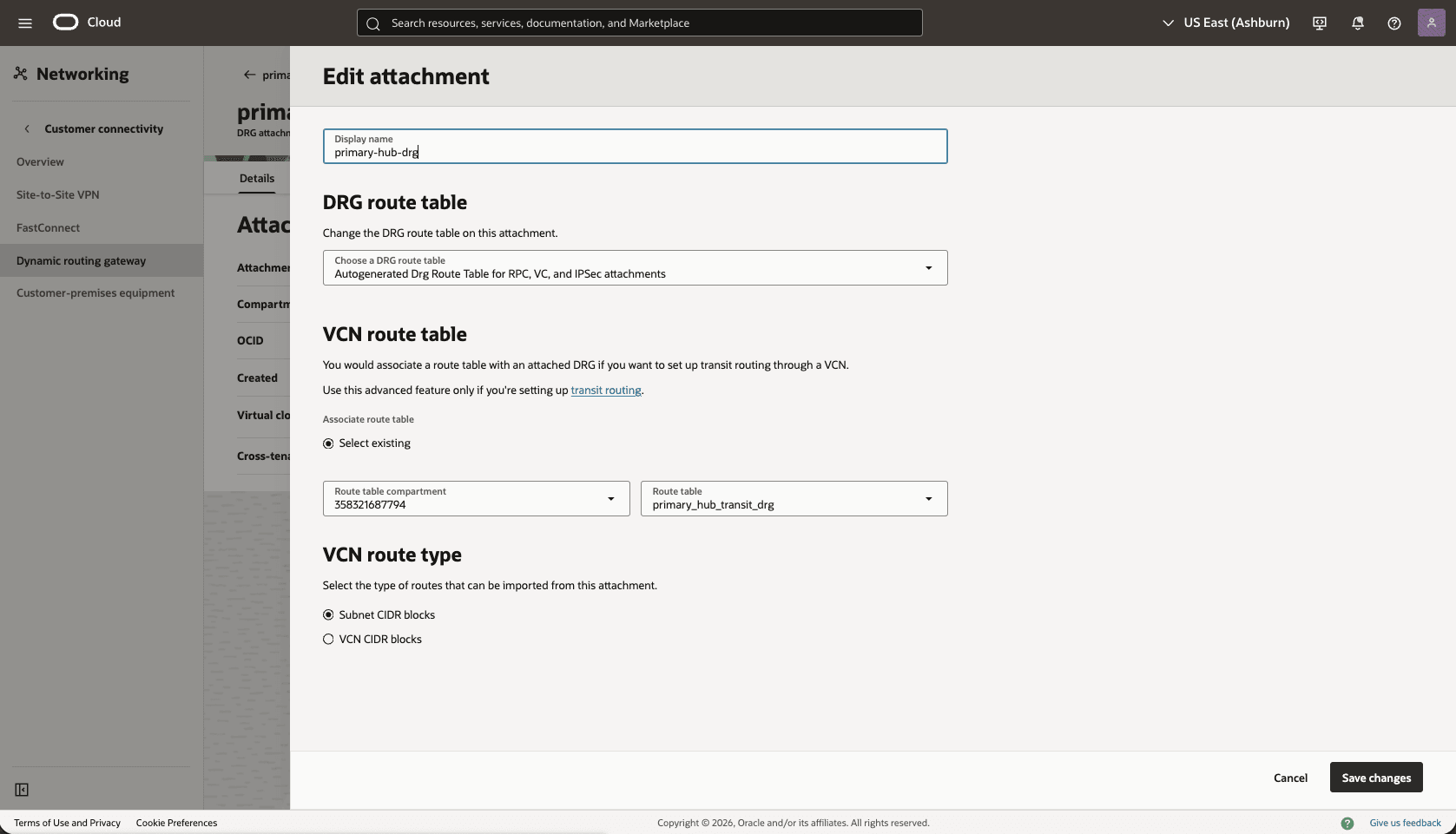
- Select the Save changes button.
- From the Hub VCN Primary VCN, select the Gateways tab. Under the Dynamic Routing Gateway Attachments section, select the name of your DRG attachment.
- Validate the DRG route table options.
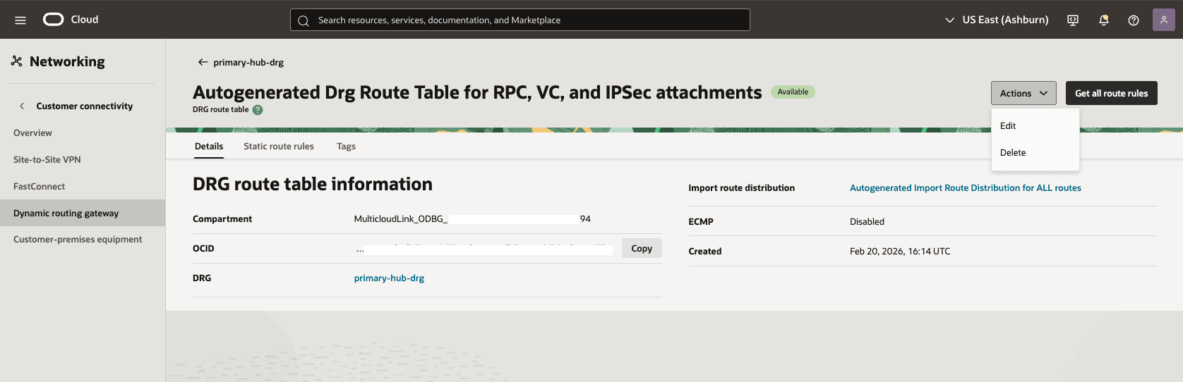
- From the Dynamic Routing Gateway section, select the Attachments tab. In the VCN attachments section, under DRG route tablecolumn, select Autogenerated Drg Route Table for RPC, VC, and IPSec attachments.
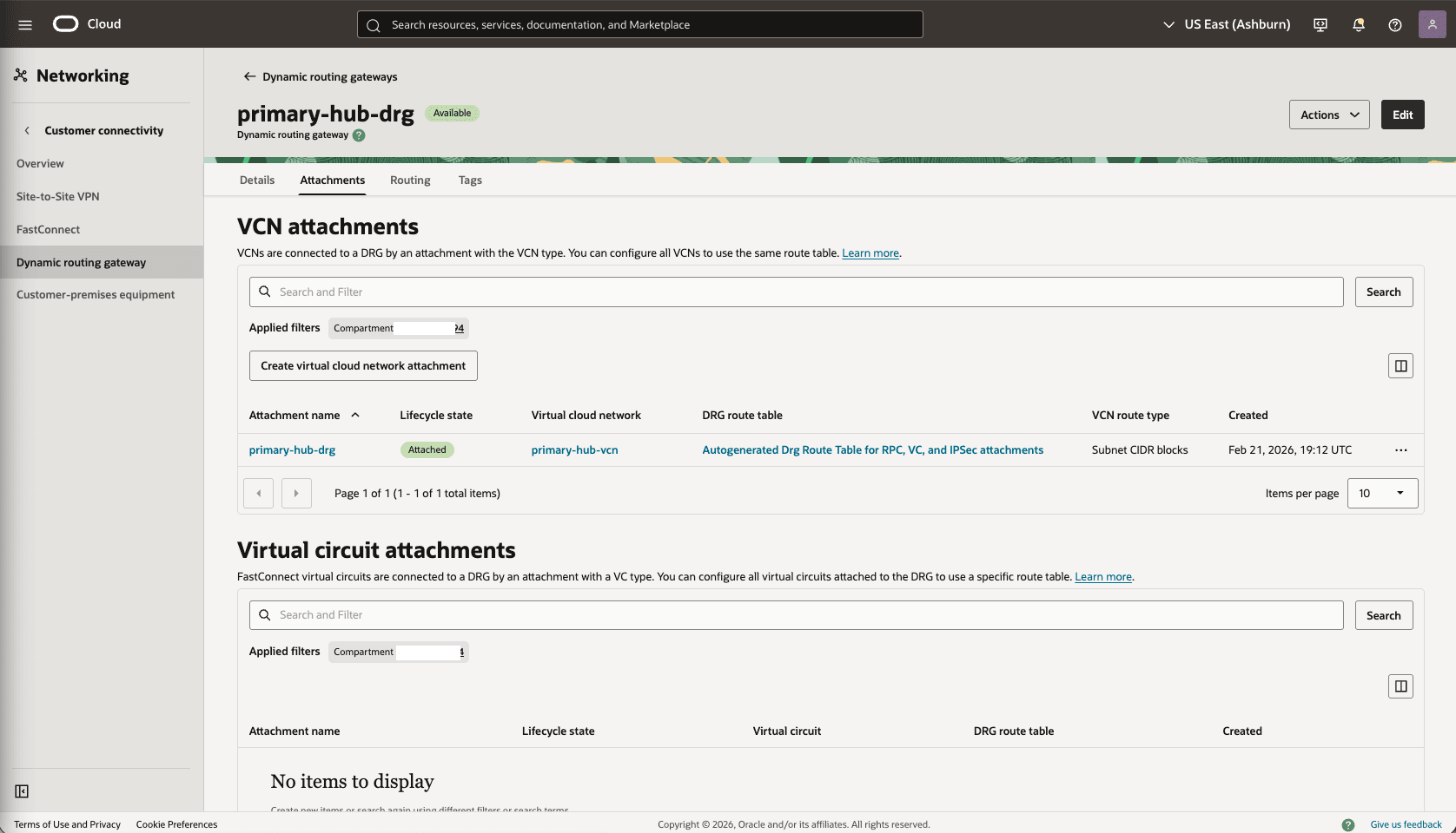
- Select the Actions button, then select the Edit option.
- Make sure that the Enable import route distribution option is enabled and Import route distribution is set to Autogenerated Import Route Distribution for ALL routes.
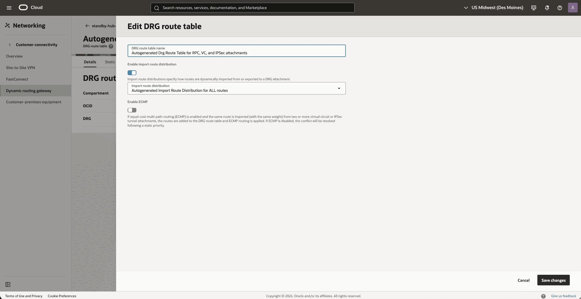
- Select the Save changes option.
Note
- For a more precise configuration, disable the import route distribution of the Autogenerated DRG Route Table for RPC, VC, and IPSec attachments route table.
- For Autogenerated DRG Route Table for VCN attachments, create and assign a new import route distribution including only the required RPC attachment.
- From the Dynamic Routing Gateway section, select the Attachments tab. In the VCN attachments section, under DRG route tablecolumn, select Autogenerated Drg Route Table for RPC, VC, and IPSec attachments.
- From the
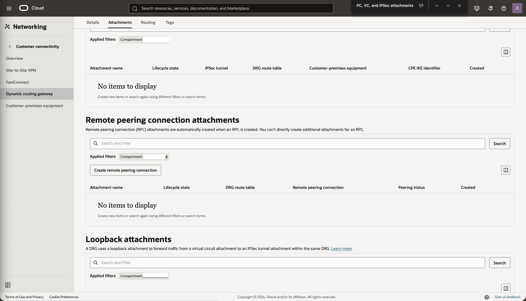
Primary-Hub-DRG, create a remote peering connection attachments.- From the Network section, in the Dynamic routing gateway page, select the Attachments tab, scroll down to the Remote peering connection attachments section, select the Create remote peering connection button.
- Choose a name. For example,
primary-hub-drg.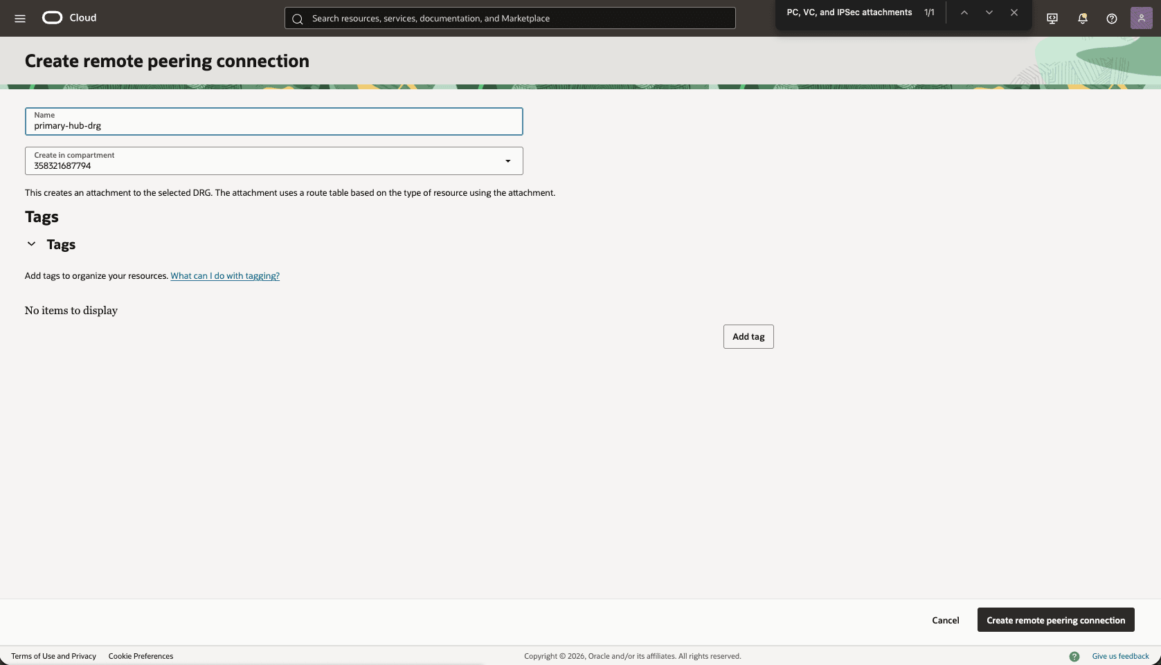
- Select the Create remote peering connection button.
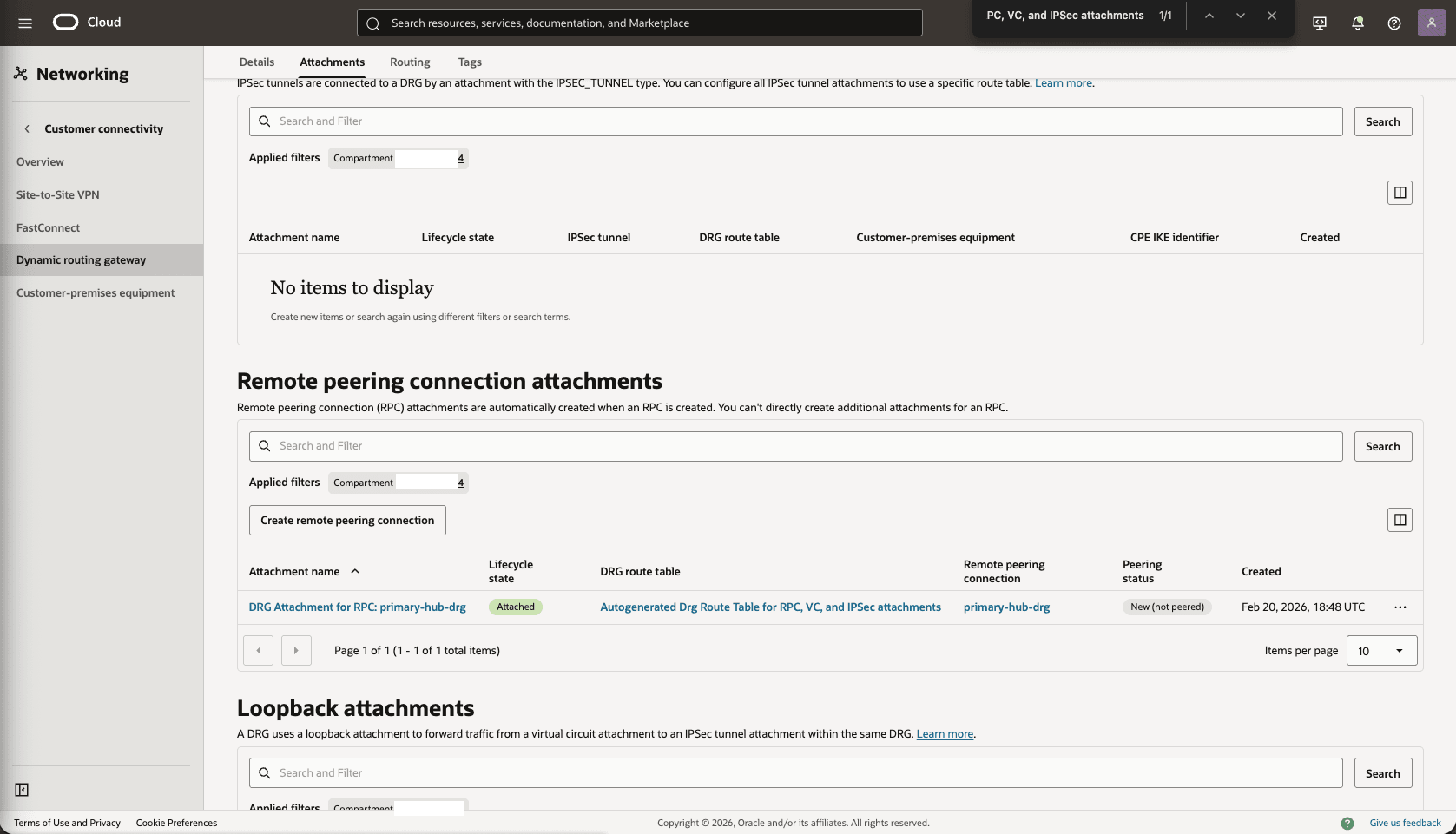
- Select the remote peering connection
primary-hub-drgthat you created in the previous step, and take note of the OCID.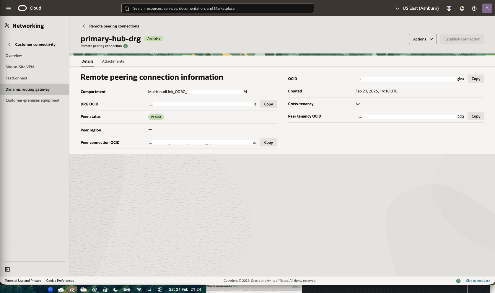
- From the Network section, in the Dynamic routing gateway page, select the Attachments tab, scroll down to the Remote peering connection attachments section, select the Create remote peering connection button.
- Update the primary VCN Default Route Table. Add a route rule for the Standby VCN Client Subnet CIDR range.
- From your Primary VM cluster VCN, select the Routing tab, then select the name of the Default Route table.
- Select the Route Rules tab, then select Add Route Rules button.
- Target Type: Local Peering Gateway
- Destination CIDR Block: select the standby VCN client subnet CIDR. For example,
10.30.1.0/24. - Target Local Peering Gateway: select your LPG. For example,
primary-vcn-lpg. - Description: Enter a description.
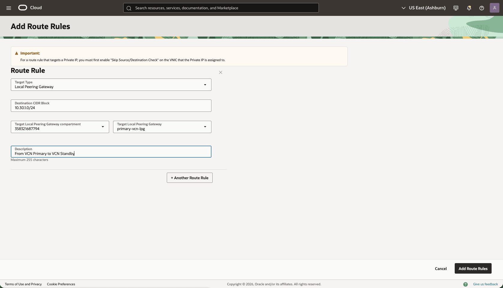
- Select the Add Route Rules button.
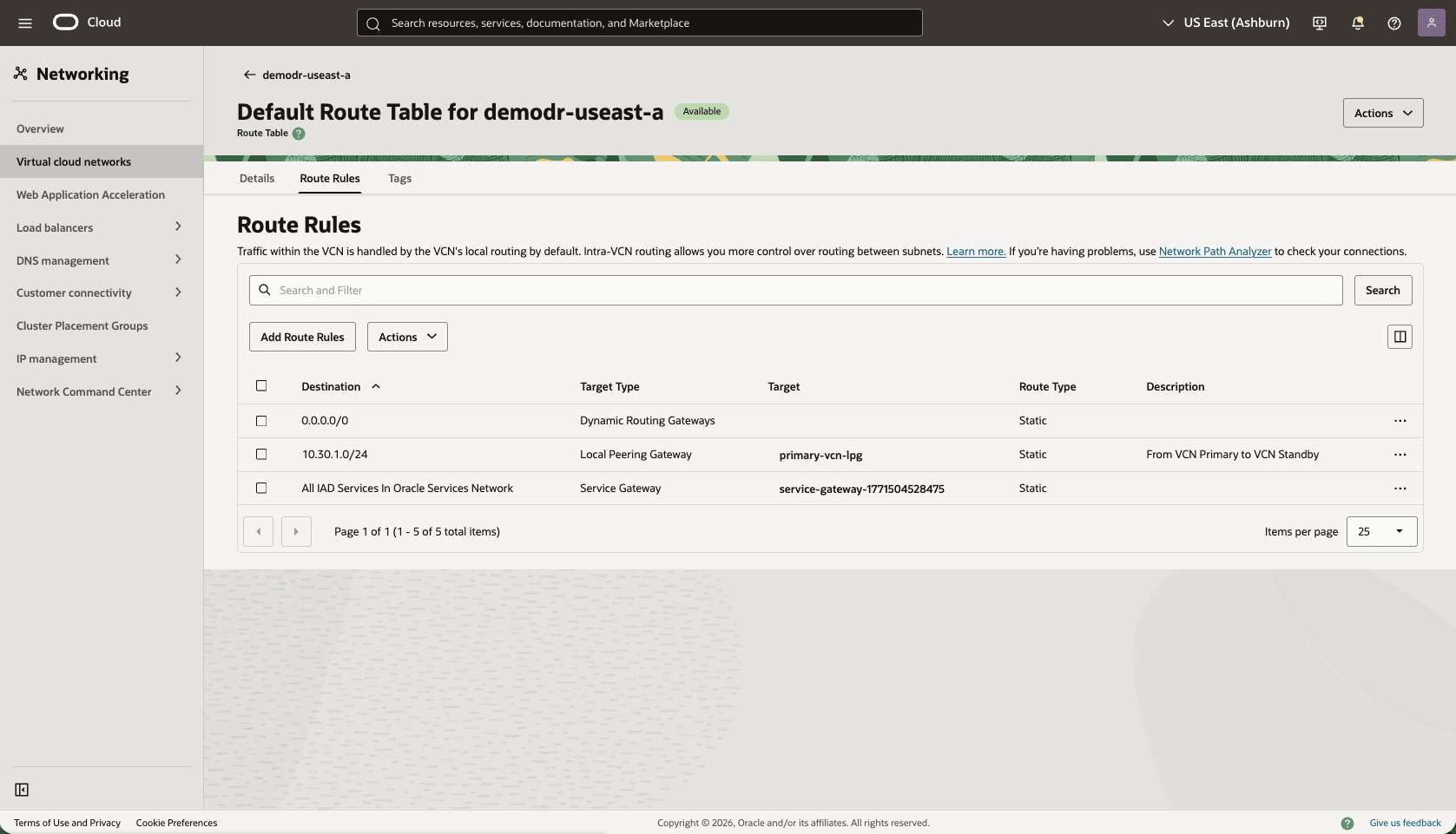
- From the OCI console, navigate to the Network section, and then select the Client network security groups.
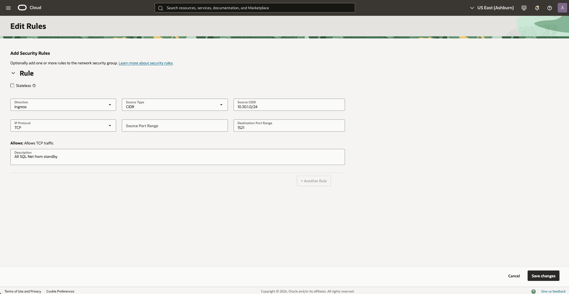
- Update the OCI network security group (NSG) of your primary VM cluster VCN to allow traffic from the standby network.
- In the Virtual Cloud Networks detail page of the primary VCN (
10.10.10.0/24), select the Security tab, scroll down to the Network Security Groups section, then select the name of your VM Cluster Network Security Groups. - Select the Security rules tab, select the Add Rules button, then create a rule with the following specifications.
- Direction: Ingress
- Source Type: CIDR
- Source CIDR: Enter your stand by CIDR block. For example,
10.30.1.0/24. - IP Protocol: TCP
- Source Port Range: Empty (All)
- Destination Port Range: 1521
- Description: Enter a description for this rule.
- Select the Add button.
- Optionally, you can add SSH port 22 to SSH the standby VM Cluster.
- In the Virtual Cloud Networks detail page of the primary VCN (
- From the OCI console, in the Networking menu, create a Virtual Cloud Network (VCN) of the standby region (HUB VCN Standby).
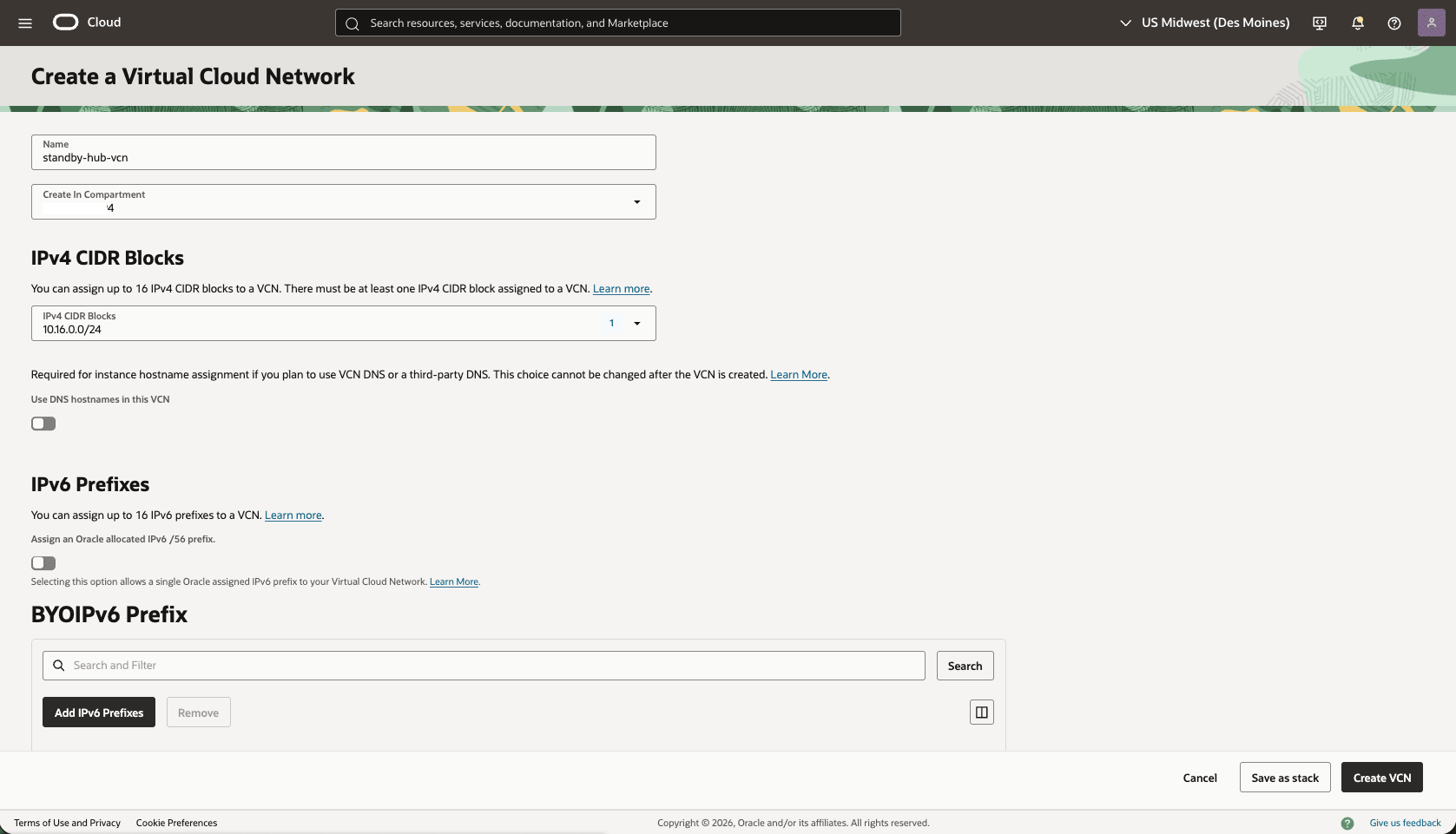
- From the OCI console, select Networking, then select Virtual cloud networks. Select Create VCN button and enter the following information.
- Name: Choose a name.For example,
standby-hub-vcn. - Create In compartment: Select the compartment that you want to create the VCN.
- Enter the CIDR block for your Hub VCN. Ensure that this block does not overlap with your existing network address space.
- Select the Create VCN button.
- Name: Choose a name.For example,
- From the OCI console, select Networking, then select Virtual cloud networks. Select Create VCN button and enter the following information.
- Deploy two local peering gateways (LPGs), Standby-Hub-LPG and Standby-LPG, in the standby hub VCN and the standby VCN, respectively.
- In the Standby-Hub VCN detail page, select the Gateways tab, scroll down to the Local Peering Gateways section, and then select the Create Local Peering Gateway button.
- Choose a name. For example,
standby-hub-lpg. Then select the Create Local Peering Gateway button.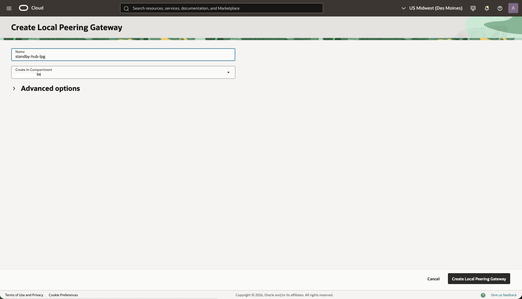
- In the Standby VM cluster VCN detail page, select the Gateways tab, scroll down to the Local Peering Gateways section, then select the Create Local Peering Gateway button.
- Choose a name. For example,
standby-lpg. Then, select the Create Local Peering Gateway button.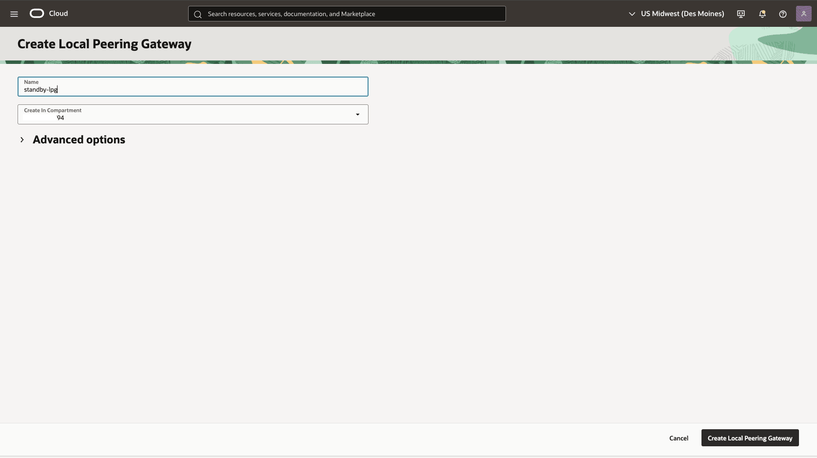
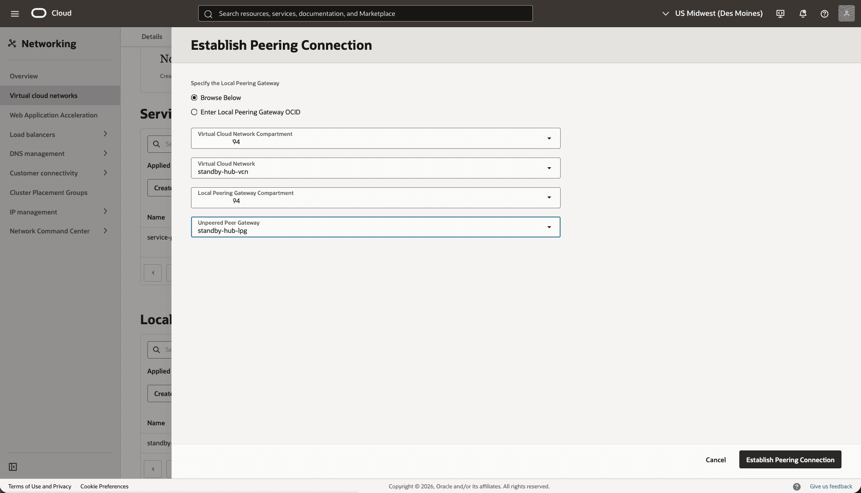
- Establish a peer LPG connection between LPGs for VCN Standby and HUB VCN Standby.
- In your Standby VM Cluster VCN, select the Gateways tab, and then select Local Peering Gateways. Locate the LPG that you created in the previous step. Select the three dots, and then select Establish Peering.
- Select the Browse Below option, select the Standby-Hub VCN, Standby-Hub-LPG, and then select the Establish Peering Connection button.
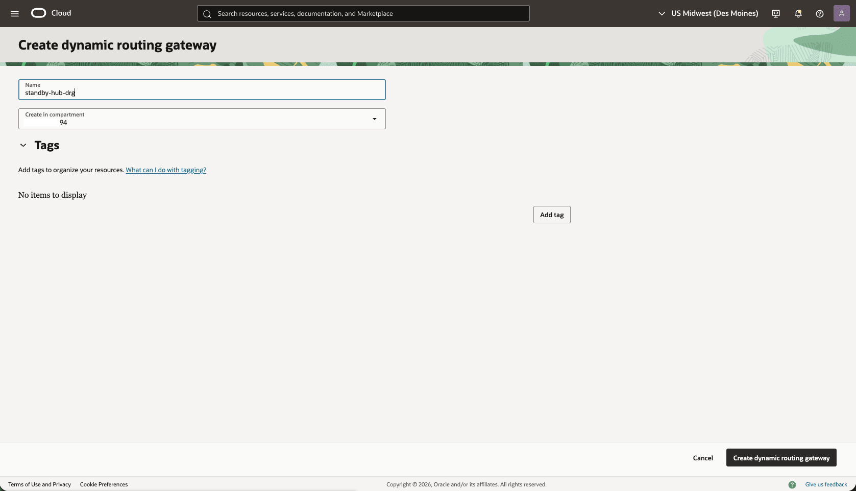
- Create a dynamic routing gateway (DRG) named
Stanby-hub-drg.- From the OCI console, select Networking. Under the Customer connectivity section, select Dynamic routing gateway, and then select Create dynamic routing gateway button.
- Choose a name. For example,
standby-hub-drg. - Select the Create dynamic routing gateway button.
- Choose a name. For example,
- From the OCI console, select Networking. Under the Customer connectivity section, select Dynamic routing gateway, and then select Create dynamic routing gateway button.
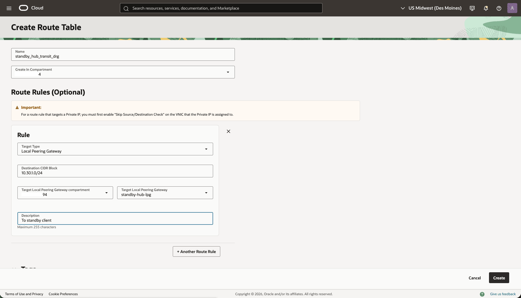
- Create a route table in the HUB VCN Standby VCN, to route the network traffic between the HUB VCN Standby and VCN Standby.
- From the OCI console, select Networking, select Virtual cloud networks, then select the HUB VCN Standby VCN.
- Select the Routing tab, then select the Create Route Table button.
- Name: Choose a name. For example,
standby_hub_transit_drg. - Select the + Another Route Rule button.
- Target Type: Local Peering Gateway
- Destination CIDR Block: Enter the Standby VM Cluster Client Subnet CIDR. For example,
10.30.1.0/24. - Target Local Peering Gateway: Select the LPG of the created in the HUB VCN Primary. For example,
standby-hub-lpg. - Description: Enter a description.
- Select the Create button.
- Name: Choose a name. For example,
- Attach the DRG to the HUB VCN Standby VCN
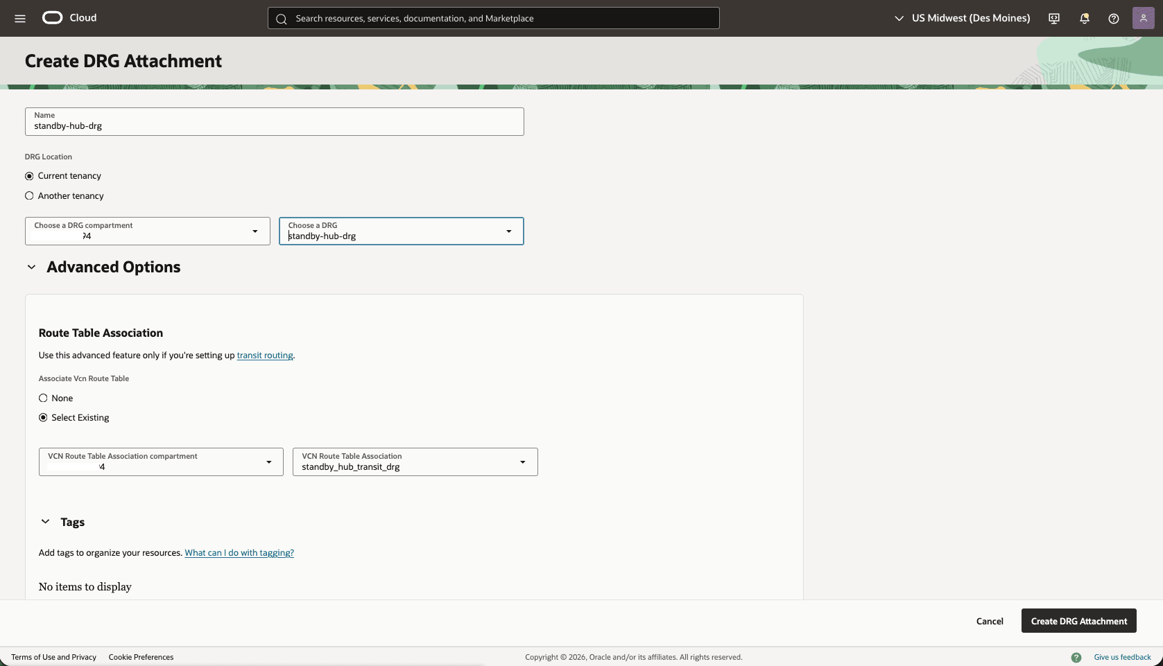
- In the HUB VCN Standby VCN, select the Gateways tab, under Dynamic Routing Gateway Attachments section, select the Create DRG Attachment button.
- Name: Select a name. For example,
standby-hub-drg. - DRG Location: Select the current tenancy
- Choose a DRG: Select the DRG name that you created in the previous step.
- The Advanced Options section is optional.
- Choose the Select Existing option, then select the Routing Table that you created in the previous step. For example,
standby_hub_transit_drg. - Select the Create DRG Attachment button.
- In the HUB VCN Standby VCN , create a second Route Table to direct network traffic to the Standby Network.
- From the HUB VCN Standby VCN, select the Routing tab, then select the Create Route Table button.
- Name: choose a name. For example,
standby_hub_transit_lpg. - Select the + Another Route Rule button.
- Target Type: Dynamic Routing Gateway
- Destination CIDR Block: Enter the VCN Primary client subnet CIDR. For example,
10.10.1.0/24. - Target Dynamic Routing Gateway: Select the DRG associated with the HUB VCN Standby VCN. For example,
standby-hub-drg. - Description: To primary VCN client subnet
- Select the Create button.
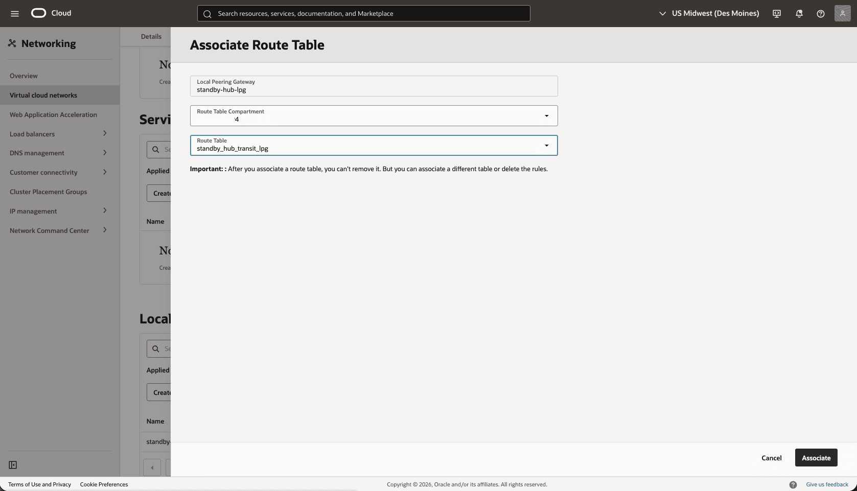
- Associate the
standby_hub_transit_lpgroute table to theHub-Standby-LPGgateway.- From the Hub VCN Primary VCN, select the Gateways tab, scroll down to the Local Peering Gateways section.
- Select the three dots, then select Associate Route Table option.
- Select the Route table that you created for the Local Peering Gateway. For example,
standby_hub_transit_lpg. - Select the Associate button.
- Edit the Standby-Hub-DRG attachment from the Standby-Hub-VCN to add DRG route table.
- From the Standby-Hub-VCN , select the Gateways tab, under Dynamic Routing Gateway Attachments section, select the name of your DRG Attachment.
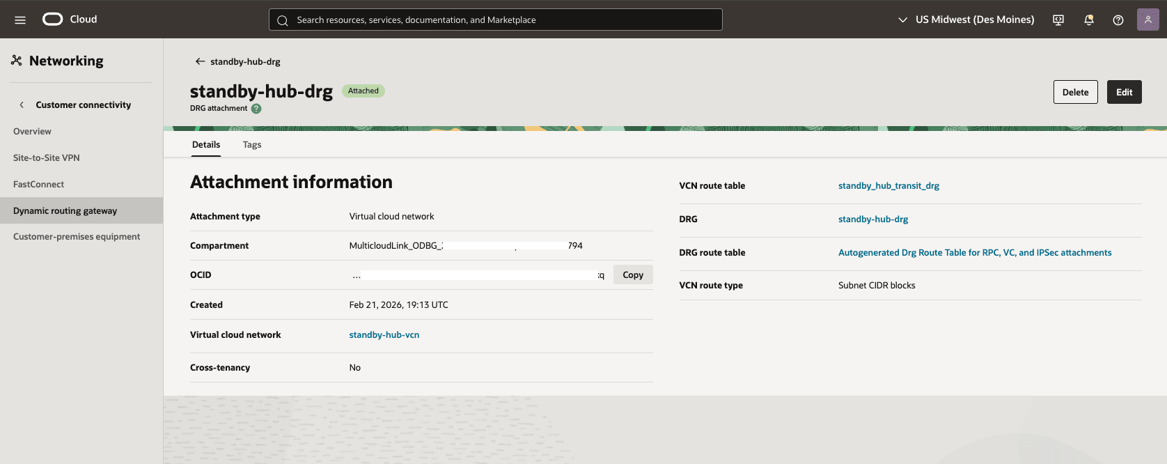
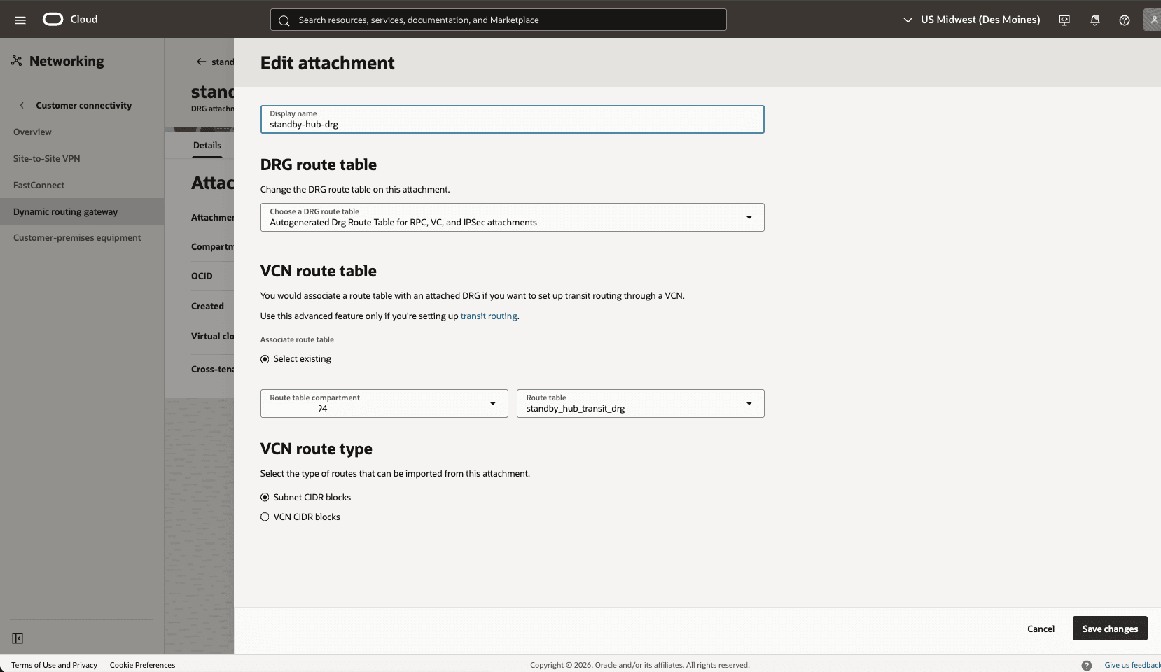
- Select the Edit button.
- In the DRG route table, select Autogenerated Drg Route Table for RPC, VC, and IPSec attachments.
- Select the Save changes button.
- From the Standby-Hub-VCN , select the Gateways tab, under Dynamic Routing Gateway Attachments section, select the name of your DRG Attachment.
- Validate the DRG route table options
- From Dynamic Routing Gateway, select the Attachments tab, in the VCN attachments section, under the DRG route table column, select Autogenerated Drg Route Table for RPC, VC, and IPSec attachments.
- select the Actions button, then select the Edit option.
- Make sure that the Enable import route distribution option is enabled and Import route distribution is set to Autogenerated Import Route Distribution for ALL routes.
- Select the Save changes option.
Note
- For a more precise configuration, disable the import route distribution of the Autogenerated DRG Route Table for RPC, VC, and IPSec attachments route table.
- For Autogenerated DRG Route Table for VCN attachments, create and assign a new import route distribution including only the required RPC attachment.
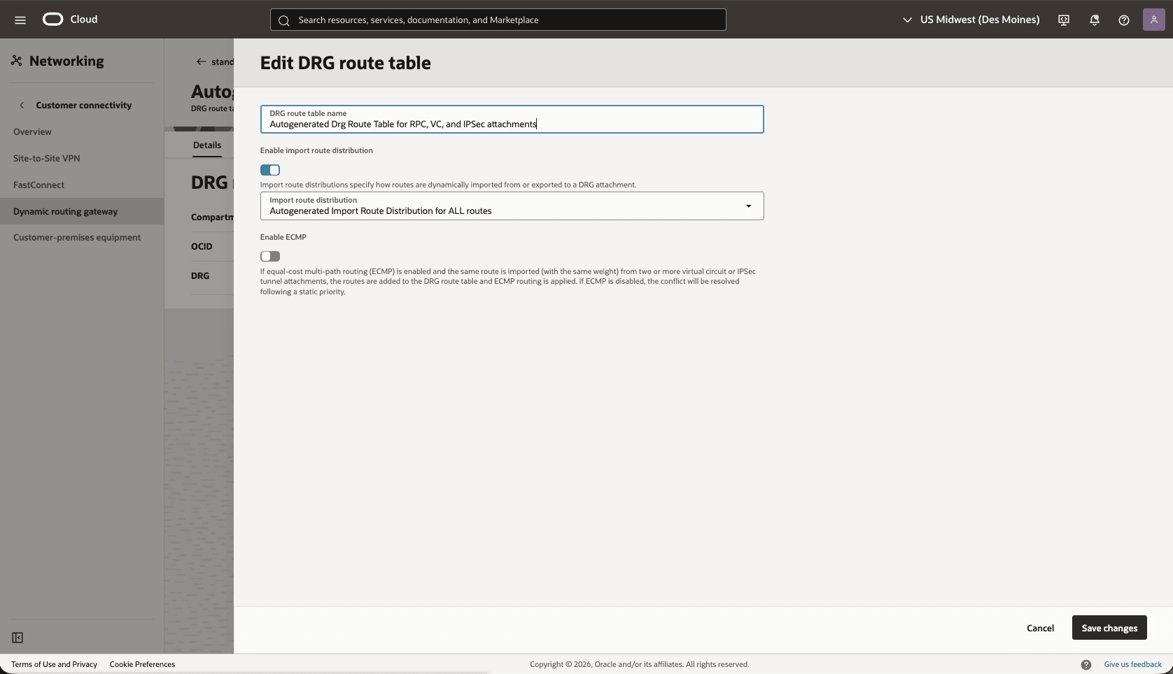
- From the
Standby-Hub-DRG, create a remote peering connection attachments.- From the Dynamic routing gateway page, select the Attachmentstab, scroll down to the Remote peering connection attachments section, and select the Create remote peering connection button.
- Choose a name. For example,
standby-hub-drg. - Select the Create remote peering connection button.
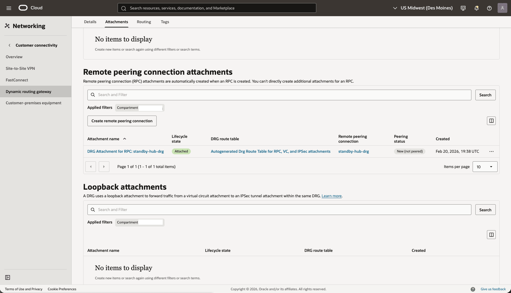
- From the
Standby-Hub-DRG, scroll down to the Remote peering connection attachments section, under Remote peering connection column, select the remote peering connection. For example,standby-hub-drg.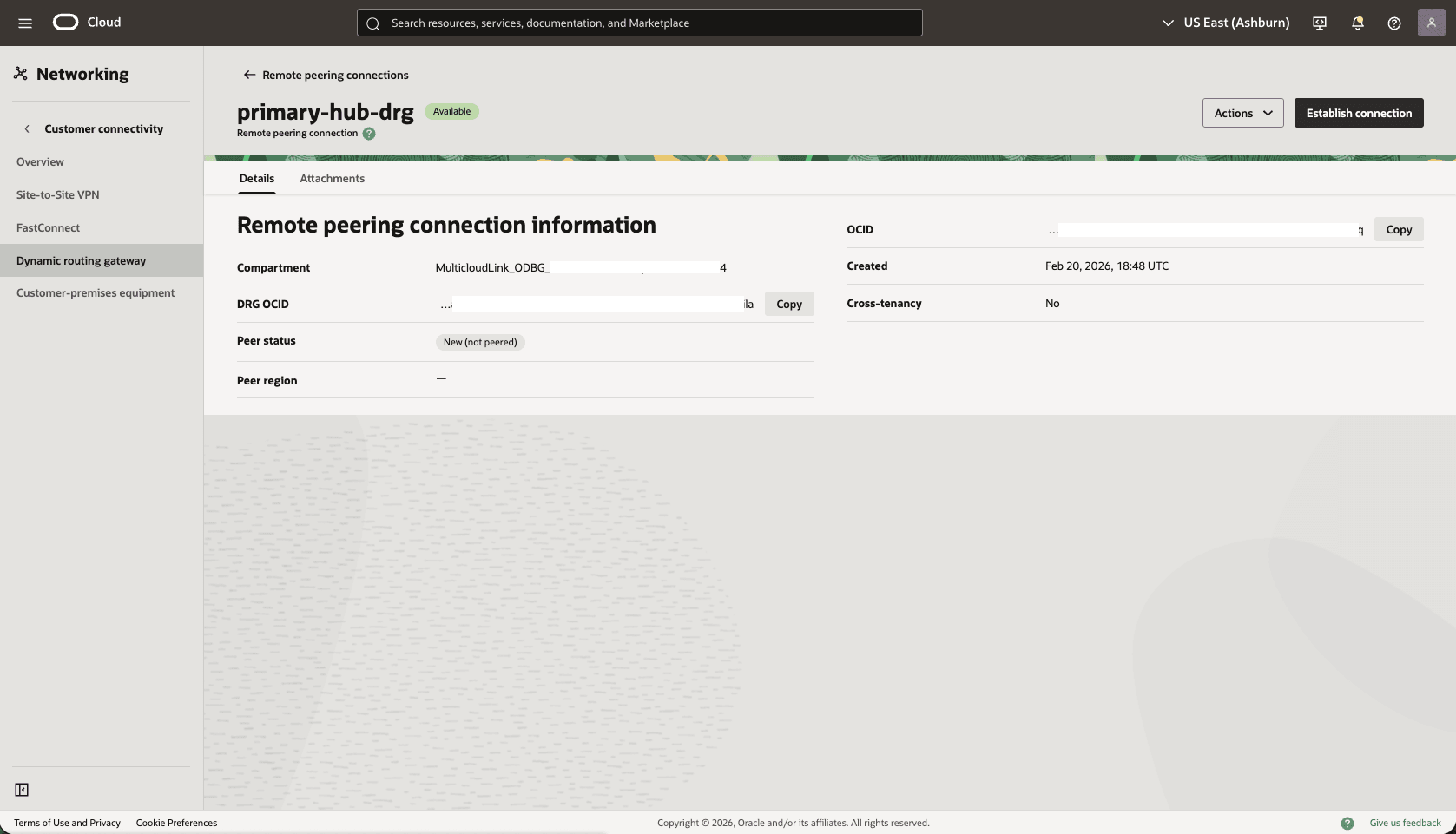
- Select the Establish Connection button and enter the following information.
- Region: Select your primary Region.
- Remote peering connection OCID: Provide the Primary-Hub-drg remote peering connection OCID captured before.
- Select the Establish connection button.
Note
When the peering status becomes peered. Both regions are connected.
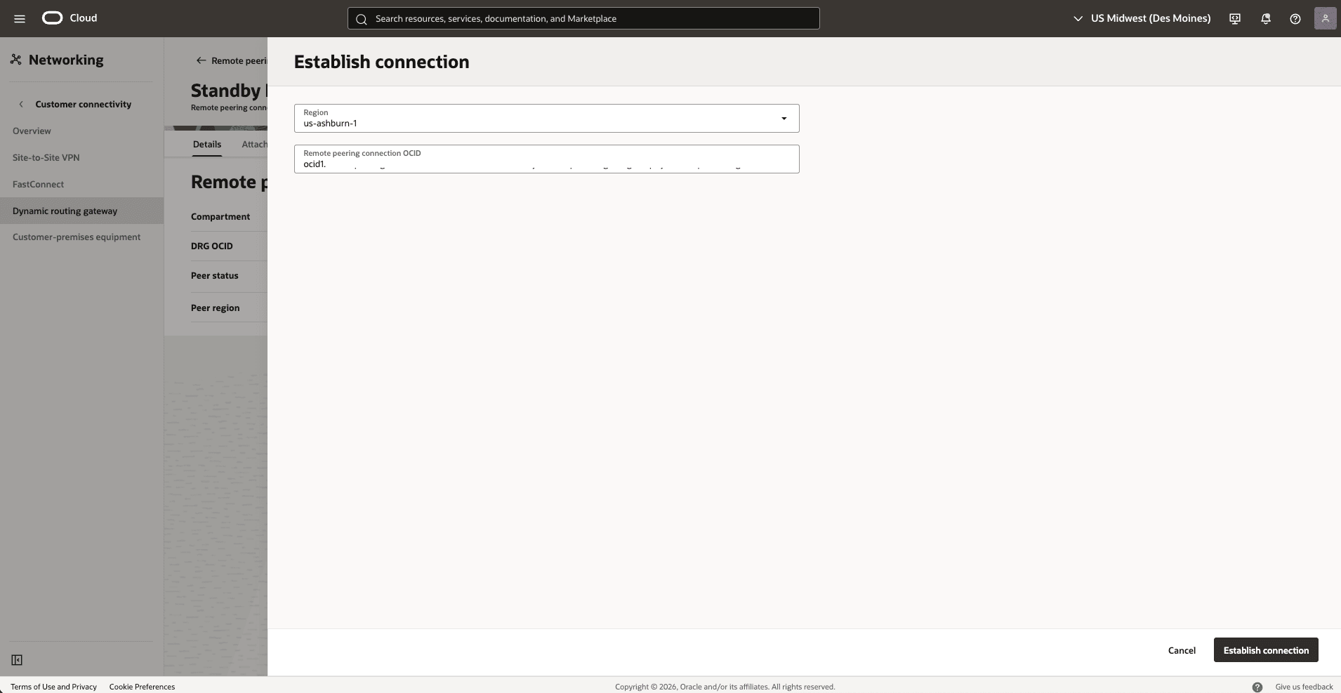
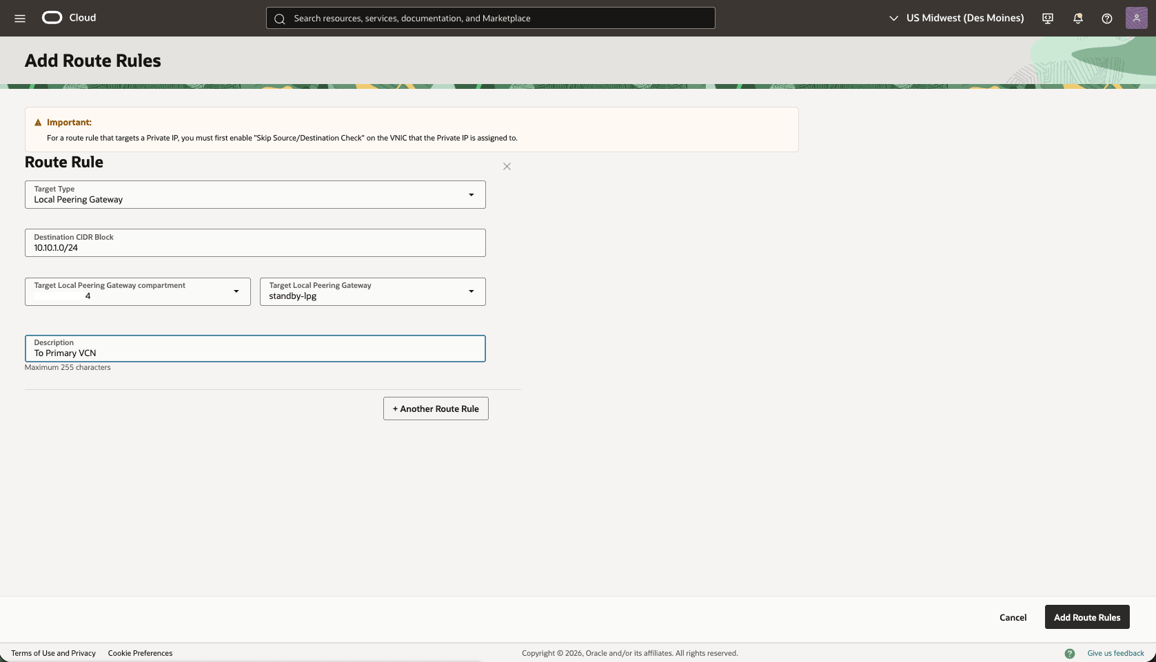
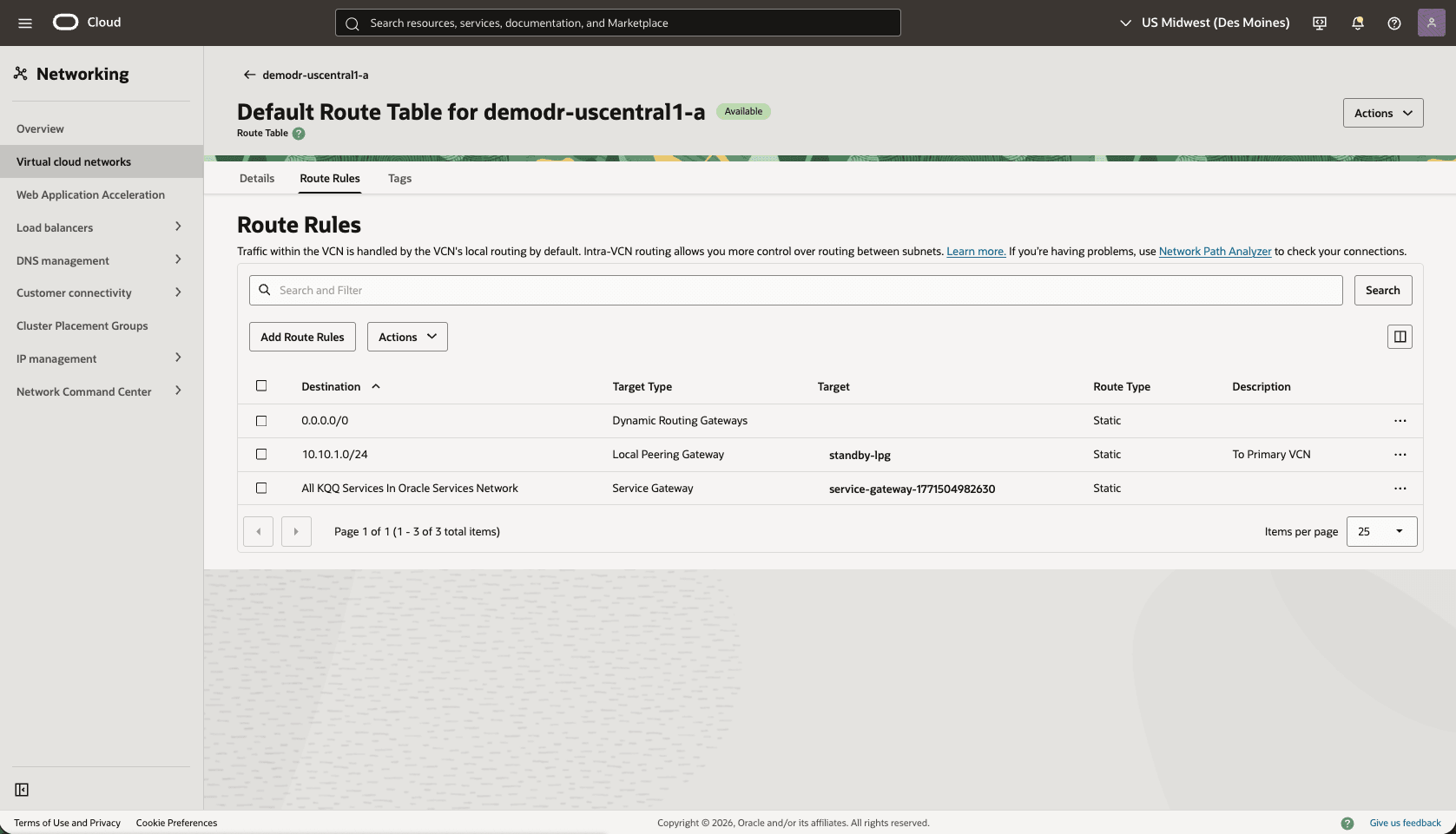
- Update the Standby VCN Default Route Table, add a route rule to the Primary VCN Client Subnet CIDR range
- From your Standby VM cluster VCN, select the Routing tab, then select the name of the Default Route table.
- Select the Route Rules tab, then select Add Route Rules button.
- Target Type: Local Peering Gateway.
- Destination CIDR Block: Select the standby VCN client subnet CIDR. For example,
10.10.1.0/24). - Target Local Peering Gateway: select your LPG. For example,
standby-lpg. - Description: Enter a description.
- Select the Add Route Rules button.
- In the VCN Standby client subnet, update the NSG to create a security rule to allow ingress for TCP port 1521. Optionally, you can add SSH port 22 for direct SSH access to the database servers.
Test Connectivity
- Test connectivity from Primary to Standby and Standby to Primary, according to the NSG you can use ping, SSH or SQL Net.
- The primary Exadata VM Cluster is deployed in the primary region in Primary VCN and the client subnet CIDR
There is currently no content for this page. Oracle AI Database@Azure team intends to add content here, and this placeholder text is provided until that text is added.
The Oracle AI Database@Azure team is excited about future new features, enhancements, and fixes to this product and this accompanying documentation. We strongly recommend you watch this page for those updates.
Connectivity by Azure Network
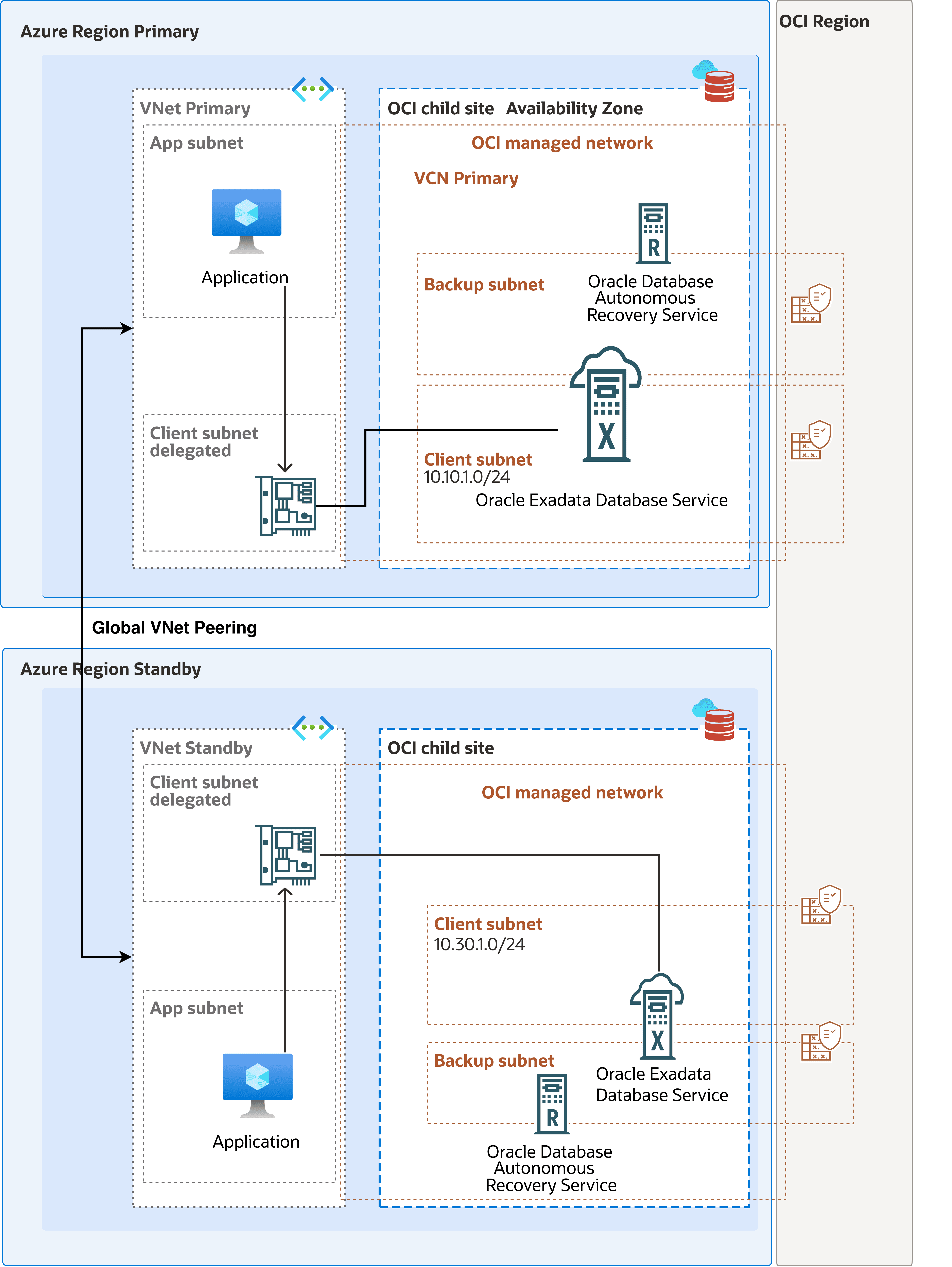
Configure the network for Oracle Data Guard between two Oracle AI Database@Azure deployments in different regions: one primary and one standby. This architecture uses Azure Global VNet peering between two Azure virtual networks (VNets). Each VNet is regional and contains one Oracle AI Database@Azure delegated subnet.
This procedure covers the Azure Portal configuration for cross-region Data Guard network preparation:
- The deployments must be in the two Azure regions.
- The deployments must be in two Azure VNets, one per region.
- One Oracle AI Database@Azure delegated subnet per VNet.
- The VNet address spaces must not overlap.
- Advanced networking must be enabled for the delegated subnets.
Note
- Global VNet peering uses Azure backend system routes and avoids the additional routing complexity, availability dependency, and throughput constraints associated with an Azure Firewall or NVA. Route Oracle Data Guard traffic through a firewall or NVA only when inspection, compliance, or an established network security architecture requires it.
- Before you deploy Oracle AI Database@Azure resources, verify that Azure Advanced Networking (
EnableRotterdamSdnApplianceForOraclefeature) is enabled in the subscription.
The following diagram illustrates the architecture diagram for configuring cross-region by Azure network.
Configuration Instructions
The following table shows an example architecture. Replace the sample names and CIDR blocks with the values for your deployment.
Component Primary Standby Azure region eastus westus3 Resource group rg-odaa-primary-eastus rg-odaa-standby-westus3 VNet vnet-odaa-primary-eastus vnet-odaa-standby-westus3 VNet CIDR 10.10.0.0/16 10.30.0.0/16 Oracle delegated subnet snet-odaa-primary snet-odaa-standby Delegated subnet CIDR 10.10.1.0/24 10.30.1.0/24 Oracle database role Primary Standby Data Guard traffic between the primary and standby database client subnets uses Azure Global VNet peering. The traffic path is bidirectional:- Primary DB client subnet 10.10.1.0/24
- Azure Global VNet peering
- Standby DB client subnet 10.30.1.0/24
- Standby DB client subnet 10.30.1.0/24
- Azure Global VNet peering
- Primary DB client subnet 10.10.1.0/24
Complete the following steps for configuration:- Create the VNet Peering
Complete the following steps to create Global VNet peering from the primary VNet to the standby VNet and from the standby VNet to the primary VNet. You can create the peering in both directions in the Azure Portal when you have permissions for both VNets.
- From the Azure Portal, navigate to Virtual networks.
- Select the VNet that you are using. For example: vnet-odaa-primary-eastus.
- From the left menu, expand the Settings section and then select Peerings.
- Select the + Add button to create a virtual network peering.
- From the Add peering page, complete the following steps:
- Enter a remote peering link name in the Peering link name field. The name must begin with a letter or number, end with a letter, number or underscore, and may contain only letters, numbers, underscores, periods, or hyphens. For example,
primary-eastus-to-standby-westus3. - Choose the Peering type as Virtual network.
- From the Subscription dropdown list, select the subscription that contains
vnet-odaa-standby-westus3. - Select your Virtual network. For example,
vnet-odaa-standby-westus3. - From the Remote virtual network peering settings section, configure remote peering settings.
- Allow the peered virtual network to access to your virtual network: This option is enabled by default. Select this option to allow traffic from the peered virtual network to your virtual network.
- Allow the peered virtual network to receive forwarded traffic from your network: Enabling this option will allow the peered virtual network to receive traffic from virtual networks peered to your virtual network.
- Allow gateway or route server in the peered virtual network to forward traffic to your virtual network: Enabling this setting will allow the VNet to receive traffic from the peered virtual networks' gateway or route server.
- Enable the peered virtual network to use your VNet's remote gateway or route server: This option can be enabled only if your VNet has a remote gateway or route server and VNet enables "Allow gateway in VNet to forward traffic to the peered virtual network". This option can be enabled in only one of the peered virtual networks' peerings.
- From the Local virtual network summary section, enter a peering link name. For example,
standby-westus3-to-primary-eastus. The name must begin with a letter or number, end with a letter, number or underscore, and may contain only letters, numbers, underscores, periods, or hyphens. - From the Local virtual network peering settings section, complete the following steps:
- Allow this virtual network to access the peered virtual network: This option is enabled by default.
- Allow forwarded traffic from this virtual network: Leave this option disabled and the checkbox unselected unless a firewall, NVAor hubforwards traffic.
- Enable gateway or route server traffic: Leave this option disabled unless you use gateway transit or Route Server.
- Review your information, and then select the Add button.
- Enter a remote peering link name in the Peering link name field. The name must begin with a letter or number, end with a letter, number or underscore, and may contain only letters, numbers, underscores, periods, or hyphens. For example,
- Verify Peering State
- From the Azure Portal, navigate to Virtual networks.
- Select the VNet that you are using. For example:
vnet-odaa-primary-eastus. - From the left menu, expand the Settings section and then select Peerings.
- Ensure that
primary-eastus-to-standby-westus3shows Connected. - From the VNet list, select
vnet-odaa-standby-westus3.. - From the left menu, expand the Settings section, and then select Peerings.
- Ensure that
standby-westus3-to-primary-eastusshows Connected.
- Direct Global VNet Peering
Use Azure system routes when traffic flows directly over Global VNet peering.
Do not create user-defined routes for the Oracle Data Guard path when:
- No firewall, NVA, virtual WAN hub, or secured hub exists between the primary and standby VNets.
- You do not need traffic inspection.
- The delegated subnet CIDRs are directly reachable through the connected Global VNet peerings.
- Configure Azure and OCI Security Rules
Configure Azure Network Security Groups (NSGs) if NSGs are enabled for the delegated subnet deployment. Then, configure matching OCI network security group or security list rules for the OCI database network. The Azure and OCI rules must allow the same primary-to-standby and standby-to-primary listener paths.
- Azure Primary Delegated Subnet NSG
- Create an inbound rule by using the following value:
Field Value Source 10.30.1.0/24 Source port ranges * Destination 10.10.1.0/24 or Any Service Custom Destination port ranges 1521 Protocol TCP Action Allow Priority Use a priority before deny rules Name allow-dg-from-standby-region - Create an outbound rule by using the following values:
Field Value Source 10.10.1.0/24 or Any Source port ranges * Destination 10.30.1.0/24 Service Custom Destination port ranges 1521 Protocol TCP Action Allow Priority Use a priority before deny rules Name allow-dg-to-standby-region
- Create an inbound rule by using the following value:
- Azure Standby Delegated Subnet NSG
- Create an inbound rule by using the following value:
Field Value Source 10.10.1.0/24 Source port ranges * Destination 10.30.1.0/24 or Any Service Custom Destination port ranges 1521 Protocol TCP Action Allow Priority Use a priority before deny rules Name allow-dg-from-primary-region - Create an outbound rule by using the following values:
Field Value Source 10.30.1.0/24 or Any Source port ranges * Destination 10.10.1.0/24 Service Custom Destination port ranges 1521 Protocol TCP Action Allow Priority Use a priority before deny rules Name allow-dg-to-primary-region
- Create an inbound rule by using the following value:
- OCI Network Security Rules
From the Oracle AI Database@Azure resources, navigate to the Go to OCI link to open the primary and standby database in the OCI Console. Identify the VCN, database client subnet, and network security group (NSG) that each database network uses. Add the required rules to the NSG attached to each database network.
Use stateful rules unless your environment requires stateless rules. If you use stateless rules, add the corresponding return-path rules for the ephemeral response ports that your security design requires.
- OCI Primary Database Network NSG
- Create an ingress rule by using the following values:
Field Value Direction Ingress Source type CIDR Source CIDR 10.30.1.0/24 IP protocol TCP Source port range All Destination port range 1521 Stateless No Description allow-dg-from-standby-region - Create an egress rule by using the following values:
Field Value Direction Egress Destination type CIDR Destination CIDR 10.30.1.0/24 IP protocol TCP Source port range All Destination port range 1521 Stateless No Description allow-dg-to-standby-region
- Create an ingress rule by using the following values:
- OCI Standby Database Network NSG
- Create an ingress rule by using the following values:
Field Value Direction Ingress Source type CIDR Source CIDR 10.10.1.0/24 IP protocol TCP Source port range All Destination port range 1521 Stateless No Description allow-dg-from-primary-region - Create an egress rule by using the following values:
Field Value Direction EgressDestination type CIDRDestination CIDR 10.10.1.0/24IP protocol TCPSource port range AllDestination port range 1521Stateless NoDescription allow-dg-to-primary-region
- Create an ingress rule by using the following values:
- OCI Primary Database Network NSG
If the database uses TCPS or custom listener ports, add separate rules for those ports. Common TCPS deployments use TCP port
2484. - Azure Primary Delegated Subnet NSG
- Test Connectivity
- Test connectivity from the Primary database to the Standby database and from the Standby database to the Primary database. You can use ping or SSH if you configure SSH access in the applicable network security group.
- To configure Oracle Data Guard, see the next sections.
There is currently no content for this page. Oracle AI Database@Azure team intends to add content here, and this placeholder text is provided until that text is added.
The Oracle AI Database@Azure team is excited about future new features, enhancements, and fixes to this product and this accompanying documentation. We strongly recommend you watch this page for those updates.