Reconfiguring the Private Cloud Appliance Network Environment
The network environment is configured during the initial setup of Private Cloud Appliance. An appliance administrator can update this configuration. However, careful planning is advised, because these settings define the connections to the on-premises network and could disrupt system operations.
It is not supported to turn off BGP authentication by changing the BGP password to null:
PCA-ADMIN> edit networkConfig adminbgppassword= Even if this command is completed successfully, BGP authentication remains active and the password is unchanged. This is not an error condition, but a security feature. To disable BGP authentication, you must do so explicitly. The command is:
PCA-ADMIN> edit networkConfig adminbgpauthentication=falseEnter the IP addresses for the uplinks exactly as they appear in the network configuration spreadsheet you filled out in preparation. The order of entry is important, especially when multiple IPs are added in the same field, because they map to specific spine and data center switches in the uplink topology.
Routing Information Cannot Be Modified
It is not supported to change routing information. This applies to network topologies configured with either dynamic or static routing.
Updating Management Node Information
You can change the IP addresses and hostnames of the management nodes.
- Using the Service Web UI
-
-
In the navigation menu, click Network Environment.
-
In the Network Environment Information page, click the Management Nodes tab.
The Management Nodes details appear.
-
In the top-right corner of the page, click Edit.
-
Click Next to navigate to the page you want to edit, then update the appropriate fields.
For field descriptions, see Initial System Installation Checklist.
-
Click Save Changes.
-
- Using the Service CLI
-
-
Display the current network configuration information using the
show NetworkConfigcommand.PCA-ADMIN> show NetworkConfig Data: Uplink Port Speed = 100 Uplink Port Count = 2 Uplink Vlan Mtu = 9216 Spine1 Ip = 10.n.n.12 Spine2 Ip = 10.n.n.13 Uplink Netmask = 255.255.255.0 Management VIP Hostname = ukpca01mn Management VIP 100g = 10.n.n.8 NTP Server(s) = 100.n.n.254 Uplink Port Fec = auto Public Ip range/list = 10.n.n.2/32,10.n.n.3/32,10.n.n.4/32,10.n.n.5/32,10.n.n.6/32,10.n.n.7/32 DNS Address1 = 206.n.n.1 DNS Address2 = 206.n.n.2 DNS Address3 = 10.n.n.197 Management Node1 Hostname = ukpca01-mn1 Management Node2 Hostname = ukpca01-mn2 Management Node3 Hostname = ukpca01-mn3 100g Management Node1 Ip = 10.n.n.9 100g Management Node2 Ip = 10.n.n.10 100g Management Node3 Ip = 10.n.n.11 Object Storage Ip = 10.n.n.1 Enable Admin Network = false Static Routing = true Spine VIP = 10.n.n.14 Uplink Gateway = 10.n.n.1 Uplink VLAN = 799 Uplink Hsrp Group = 61 BGP Authentication = false -
Use the
edit NetworkConfigcommand to change any of these management node parameters:-
Management Node 1 IP
-
Management Node 1 Hostname
-
Management Node 2 IP
-
Management Node 2 Hostname
-
Management Node 3 IP
-
Management Node 3 Hostname
-
Management Node VIP
-
Management Node VIP Hostname
PCA-ADMIN> edit NetworkConfig mgmt01Ip100g=172.n.n.190 mgmt02Ip100g=172.n.n.191 JobId: 52f5177d-402a-4a52-98fe-1cff9c1f26be -
-
Updating the Data Center Uplink Configuration
You can change the parameters of the physical connection between Private Cloud Appliance and the on-premises network.
Reconfiguring the connection to the data center causes an interruption of all network connectivity to and from the appliance. No network traffic is possible while the physical connections are reconfigured. All connections are automatically restored when the configuration update is complete.
- Using the Service Web UI
-
-
In the navigation menu, click Network Environment.
-
In the Network Environment Information page, click the Uplink tab.
The Uplink details appear.
-
In the top-right corner of the page, click Edit.
-
Click Next to navigate to the page you want to edit, then update the appropriate fields.
For field descriptions, see Initial System Installation Checklist.
-
Click Save Changes.
-
- Using the Service CLI
-
-
Display the current network configuration information using the
show NetworkConfigcommand.PCA-ADMIN> show NetworkConfig Data: Uplink Port Speed = 100 Uplink Port Count = 2 Uplink Vlan Mtu = 9216 Spine1 Ip = 10.n.n.12 Spine2 Ip = 10.n.n.13 Uplink Netmask = 255.255.255.0 Management VIP Hostname = ukpca01mn Management VIP 100g = 10.n.n.8 NTP Server(s) = 100.n.n.254 Uplink Port Fec = auto Public Ip range/list = 10.n.n.2/32,10.n.n.3/32,10.n.n.4/32,10.n.n.5/32,10.n.n.6/32,10.n.n.7/32 DNS Address1 = 206.n.n.1 DNS Address2 = 206.n.n.2 DNS Address3 = 10.n.n.197 Management Node1 Hostname = ukpca01-mn1 Management Node2 Hostname = ukpca01-mn2 Management Node3 Hostname = ukpca01-mn3 100g Management Node1 Ip = 10.n.n.9 100g Management Node2 Ip = 10.n.n.10 100g Management Node3 Ip = 10.n.n.11 Object Storage Ip = 10.n.n.1 Enable Admin Network = false Static Routing = true Spine VIP = 10.n.n.14 Uplink Gateway = 10.n.n.1 Uplink VLAN = 799 Uplink Hsrp Group = 61 BGP Authentication = false -
Use the
edit NetworkConfigcommand to change any of these data center uplink parameters:-
Uplink Port Speed
-
Uplink Port Count
-
Uplink VLAN MTU
-
Uplink Port FEC
PCA-ADMIN> edit NetworkConfig uplinkPortCount=2 JobId: 42f5137f-122a-4a52-98fe-1cfv9c1f26ve -
-
Updating the Administration Network Configuration
If you use the optional Administration Network, you can update the parameters using these procedures.
If you are not currently using a separate Administration Network, the Network Environment Information page in the Service Web UI will not display an Admin Network tab or any of the related configuration parameters. The command output in the Service CLI will not display any Admin Network parameters either. You must first enable the Administration Network.
When an Administration Network is configured, it cannot be disabled again.
- Using the Service Web UI
-
Scenario 1: Administration Network Disabled
If you need to enable and configure a separate Administration Network, proceed as follows:
-
In the navigation menu, click Network Environment.
-
In the top-right corner of the page, click Edit.
-
In the wizard, navigate to the Admin Network tab and set Admin Networking to Enable.
-
Enter all the required parameters in the respective fields on the form.
-
Click Save Changes.
-
- Using the Service CLI
-
-
If you are not currently using a separate Administration Network, the CLI output will not display any Admin Network parameters. Enable the Administration Network first.
-
Display the current network configuration information using the
show NetworkConfigcommand.PCA-ADMIN> show NetworkConfig Data: Uplink Port Speed = 100 Uplink Port Count = 4 Uplink Vlan Mtu = 9216 Spine1 Ip = 10.10.10.97,10.10.10.101 Spine2 Ip = 10.10.10.99,10.10.10.103 Uplink Netmask = 255.255.255.254,255.255.255.254 Management VIP Hostname = mypca Management VIP = 10.10.10.107 NTP Server(s) = 10.80.211.105,10.211.17.1,10.68.48.1 Uplink Port Fec = auto Public Ip range/list = 10.10.10.114/31,10.10.10.116/31,10.10.10.118/31,10.10.10.120/31,10.10.10.122/31,10.10.10.124/31,10.10.10.126/32 Management Node1 Hostname = pcamn01 Management Node2 Hostname = pcamn02 Management Node3 Hostname = pcamn03 Management Node1 Ip = 10.10.10.108 Management Node2 Ip = 10.10.10.109 Management Node3 Ip = 10.10.10.110 Object Storage Ip = 10.10.10.113 Enable Admin Network = true Admin Port Speed = 100 Admin Port Count = 1 Admin Vlan Mtu = 9216 Admin Port Fec = auto Admin VLAN = 3915 Admin Spine1 Ip = 10.25.0.111 Admin Spine2 Ip = 10.25.0.112 Admin Spine VIP = 10.25.0.110 Admin Netmask = 255.255.255.0 Admin Hsrp Group = 152 Static Routing = false Uplink VLAN = 3911 Peer1 Asn = 50000 Peer1 Ip = 10.10.10.96,10.10.10.98 Oracle Asn = 136025 Bgp Topology = mesh Peer2 Asn = 50000 Peer2 Ip = 10.10.10.100,10.10.10.102 BGP Authentication = false BGP KeepAlive Timer = 60 BGP Holddown Timer = 180 Network Config Lifecycle State = ACTIVE admin DNS Address1 = 10.25.0.1 admin Management Node1 Hostname = pcamn01admin.example.com admin Management Node2 Hostname = pcamn02admin.example.com admin Management Node3 Hostname = pcamn03admin.example.com admin Management Node1 Ip = 10.25.0.101 admin Management Node2 Ip = 10.25.0.102 admin Management Node3 Ip = 10.25.0.103 admin Management VIP Hostname = mypcaadmin.example.com admin Management VIP = 10.25.0.100 -
Use the
edit NetworkConfigcommand to change any of these administration network parameters:Tip
Enter
edit networkConfig ?to display the parameters available for editing.-
Admin Network enable
-
Management node cluster Admin VIP and host name
-
Management node 1-3 Admin IP and host name
-
Admin DNS IP 1-3
-
Admin Port count, speed, FEC
-
Admin CIDR
-
Admin VLAN and MTU
-
Admin Gateway IP
-
Admin Netmask
-
Spine 1+2 Admin IP
-
Spine Admin VIP
PCA-ADMIN> edit NetworkConfig adminPortSpeed=25 JobId: 62f8137f-772a-4a52-98f4-1cfv9c1f24te PCA-ADMIN> edit NetworkConfig adminCidr=10.25.0.1/24 JobId: 861381ae-cc63-44a2-a66e-8e095e4a99f9 -
-
Updating NTP Server Information
You can check the NTP connection status of a running system at any time. In the Service Web UI, it's displayed in the NTP tab of the Network Environment Information page. In the Service CLI you can run this command:
PCA-ADMIN> checkNtpServers
Data:
  id              Accessible
  --              ----------
  10.64.0.252     true
  192.0.2.2       true
You can edit or add IP addresses for NTP servers.
- Using the Service Web UI
-
-
In the navigation menu, click Network Environment.
-
In the Network Environment Information page, click the NTP tab.
The NTP details appear.
-
In the top-right corner of the page, click Edit.
-
Click Next to navigate to the page you want to edit, then update the appropriate fields.
For field descriptions, see Initial System Installation Checklist.
-
Click Save Changes.
-
- Using the Service CLI
-
-
Display the current network configuration information using the
show NetworkConfigcommand.PCA-ADMIN> show NetworkConfig Data: Uplink Port Speed = 100 Uplink Port Count = 2 Uplink Vlan Mtu = 9216 Spine1 Ip = 10.n.n.12 Spine2 Ip = 10.n.n.13 Uplink Netmask = 255.255.255.0 Management VIP Hostname = ukpca01mn Management VIP 100g = 10.n.n.8 NTP Server(s) = 100.n.n.254 Uplink Port Fec = auto Public Ip range/list = 10.n.n.2/32,10.n.n.3/32,10.n.n.4/32,10.n.n.5/32,10.n.n.6/32,10.n.n.7/32 DNS Address1 = 206.n.n.1 DNS Address2 = 206.n.n.2 DNS Address3 = 10.n.n.197 Management Node1 Hostname = ukpca01-mn1 Management Node2 Hostname = ukpca01-mn2 Management Node3 Hostname = ukpca01-mn3 100g Management Node1 Ip = 10.n.n.9 100g Management Node2 Ip = 10.n.n.10 100g Management Node3 Ip = 10.n.n.11 Object Storage Ip = 10.n.n.1 Enable Admin Network = false Static Routing = true Spine VIP = 10.n.n.14 Uplink Gateway = 10.n.n.1 Uplink VLAN = 799 Uplink Hsrp Group = 61 BGP Authentication = false -
Use the
edit NetworkConfigcommand to change the NTP servers. Enter multiple IP addresses in a comma-separated list:PCA-ADMIN> edit NetworkConfig ntpIps=100.n.n.254,100.n.n.253 JobId: 42f5137f-122a-4a52-98fe-1cfv9c1f26ve
-
Updating DNS Server Information
You can edit or add IP addresses for DNS servers.
- Using the Service Web UI
-
-
In the navigation menu, click Network Environment.
-
In the Network Environment Information page, click the DNS tab.
The DNS details appear.
-
In the top-right corner of the page, click Edit.
-
Click Next to navigate to the page you want to edit, then update the appropriate fields.
For field descriptions, see Initial System Installation Checklist.
-
Click Save Changes.
-
- Using the Service CLI
-
-
Display the current network configuration information using the
show NetworkConfigcommand.PCA-ADMIN> show NetworkConfig Data: Uplink Port Speed = 100 Uplink Port Count = 2 Uplink Vlan Mtu = 9216 Spine1 Ip = 10.n.n.12 Spine2 Ip = 10.n.n.13 Uplink Netmask = 255.255.255.0 Management VIP Hostname = ukpca01mn Management VIP 100g = 10.n.n.8 NTP Server(s) = 100.n.n.254 Uplink Port Fec = auto Public Ip range/list = 10.n.n.2/32,10.n.n.3/32,10.n.n.4/32,10.n.n.5/32,10.n.n.6/32,10.n.n.7/32 DNS Address1 = 206.n.n.1 DNS Address2 = 206.n.n.2 DNS Address3 = 10.n.n.197 Management Node1 Hostname = ukpca01-mn1 Management Node2 Hostname = ukpca01-mn2 Management Node3 Hostname = ukpca01-mn3 100g Management Node1 Ip = 10.n.n.9 100g Management Node2 Ip = 10.n.n.10 100g Management Node3 Ip = 10.n.n.11 Object Storage Ip = 10.n.n.1 Enable Admin Network = false Static Routing = true Spine VIP = 10.n.n.14 Uplink Gateway = 10.n.n.1 Uplink VLAN = 799 Uplink Hsrp Group = 61 BGP Authentication = false -
Use the
edit NetworkConfigcommand to change the DNS IP addresses:-
DNS IP1
-
DNS IP2
-
DNS IP3
PCA-ADMIN> edit NetworkConfig DnsIp2=206.n.n.2 JobId: 42f5137f-122a-4a52-98fe-1cfv9c1f26ve -
-
Updating the Public IP Address Configuration
You can add public IP addresses, or change the currently configured IP addresses.
Changing public IP addresses that are in use can cause system disruption.
- Using the Service Web UI
-
-
In the navigation menu, click Network Environment.
-
In the Network Environment Information page, click the Uplink tab.
The Uplink details appear.
-
In the top-right corner of the page, click Edit.
-
Click Next to navigate to the page you want to edit, then update the appropriate fields.
For field descriptions, see Initial System Installation Checklist.
-
Click Save Changes.
-
- Using the Service CLI
-
-
Display the current network configuration information using the
show NetworkConfigcommand.PCA-ADMIN> show NetworkConfig Data: Uplink Port Speed = 100 Uplink Port Count = 2 Uplink Vlan Mtu = 9216 Spine1 Ip = 10.n.n.12 Spine2 Ip = 10.n.n.13 Uplink Netmask = 255.255.255.0 Management VIP Hostname = ukpca01mn Management VIP 100g = 10.n.n.8 NTP Server(s) = 100.n.n.254 Uplink Port Fec = auto Public Ip range/list = 10.n.n.2/32,10.n.n.3/32,10.n.n.4/32,10.n.n.5/32,10.n.n.6/32,10.n.n.7/32 DNS Address1 = 206.n.n.1 DNS Address2 = 206.n.n.2 DNS Address3 = 10.n.n.197 Management Node1 Hostname = ukpca01-mn1 Management Node2 Hostname = ukpca01-mn2 Management Node3 Hostname = ukpca01-mn3 100g Management Node1 Ip = 10.n.n.9 100g Management Node2 Ip = 10.n.n.10 100g Management Node3 Ip = 10.n.n.11 Object Storage Ip = 10.n.n.1 Enable Admin Network = false Static Routing = true Spine VIP = 10.n.n.14 Uplink Gateway = 10.n.n.1 Uplink VLAN = 799 Uplink Hsrp Group = 61 BGP Authentication = false -
Use the
edit NetworkConfigcommand to change the public IP addresses or the object storage public IP address:-
Object Storage Public IP
-
Public IP Range/List
PCA-ADMIN> edit NetworkConfig PublicIps= 10.n.n.17/32,10.n.n.18/32,10.n.n.19/32 JobId: 42f5137f-122a-4a52-98fe-1cfv9c1f26ve -
-
Configuring Appliance Proxy Settings
The initial appliance setup procedure, as described in Completing the Initial Setup and Configuration, provides no option to add a system-wide proxy configuration. However, some of the platform and infrastructure services require connectivity to endpoints outside the appliance environment. For example, for federation with an identity provider (IDP), the IAM and Admin services must acquire metadata from that external server (for users of the Compute Enclave and Service Enclave respectively.) If network traffic passes through a proxy server in the data center, requests between the appliance and the external server cannot be completed successfully.
To enable external network communication through a data center proxy server, add the proxy configuration to the appliance network setup. Ensure that the initial appliance setup procedure has been completed first.
- Using the Service Web UI
-
-
In the PCA Config navigation menu, click Appliance Details.
The Appliance Details page contains system properties such as realm, region and domain.
-
To configure a proxy at the appliance level, click the Set Rack-Wide Proxy button in the top-right corner.
A proxy configuration window appears.
-
Fill out the proxy configuration parameters:
-
Proxy Name: Enter the fully qualified domain name of the proxy server.
-
Proxy Host: Enter the proxy server IP address.
-
Proxy Port: Enter the port number the proxy server uses for routing requests.
-
Proxy User Name: If required, enter a user name for authentication with the proxy server.
-
Proxy Password: If required, enter the password for the proxy user name.
-
Proxy Confirm Password: If required, enter the proxy password again for confirmation.
The user name and password parameters are optional, in case the proxy server requires authentication. The details are stored in the Secret Service (Vault), where services can retrieve them securely to establish their external connection.
-
-
Click Set Rack-Wide Proxy to save the proxy configuration.
The proxy configuration is displayed in a separate tab on Appliance Details page.
-
To delete the proxy configuration from the appliance, go to the Appliance Details page and click Clear Rack-Wide Proxy in the top-right corner.
-
If you need to modify the stored proxy configuration, delete it and fill out the proxy configuration window again with the correct parameters.
-
- Using the Service CLI
-
-
Add the proxy configuration details using the
setProxycommand.Syntax (entered on a single line):
PCA-ADMIN> setProxy
proxyName=<proxy_fqdn>
proxyHost=<proxy_ip>
proxyPort=<proxy_port>
proxyUsername=<proxy_user>
proxyPassword=<proxy_password>
proxyConfirmPassword=<proxy_password>
Example:
PCA-ADMIN> setProxy proxyName=myproxy.example.com
proxyHost=172.16.0.100
proxyPort=8080
proxyUsername=proxyuser
proxyPassword=********
proxyConfirmPassword=********
The user name and password parameters are optional, in case the proxy server requires authentication. The details are stored in the Secret Service (Vault), where services can retrieve them securely to establish their external connection.
-
To delete the proxy configuration from the appliance, enter the
clearProxycommand. No command parameters are required. -
If you need to modify the stored proxy configuration, run the
setProxycommand again with the correct parameters.
-
Enabling External IPv6 Connectivity
The connection between Private Cloud Appliance and the on-premises network can optionally be configured to support IPv6 traffic. This is a dual stack implementation, meaning an IPv4 base configuration is applied during initial system installation and configuration, and IPv6 support is enabled in parallel.
IPv6 virtual network connectivity is currently only supported for compute instances with SR-IOV (single root I/O virtualization) VNICs.
Keep equivalent IPv4 and IPv6 addresses and CIDRs easy to identify by using a human readable conversion scheme.
- Using the Service Web UI (preferred)
-
IPv6 compute instance connectivity requires IPv6 packets to be routed over the uplinks and into the subnets where the compute instances have an IPv6 address. The Service Web UI provides a network configuration page for this purpose.
-
In the navigation menu, under PCA Config, select IPv6 Network Environment.
-
In the IPv6 Network Environment Information page, in the upper right corner, click Edit.
The IPv6 Network Configuration window is displayed.
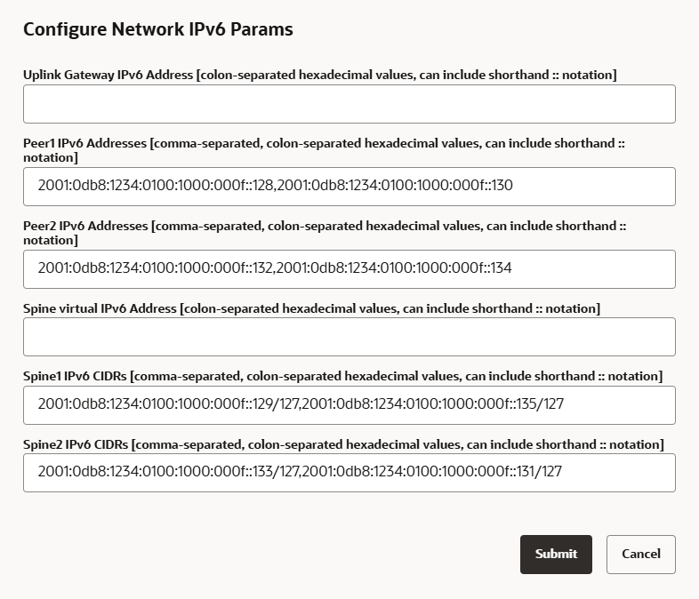
-
Fill out the required IPv6 parameters for the system uplinks.
The example shows a mesh topology with dynamic routing. For static routing, uplink gateway and spine virtual IPs are required parameters.
-
Click Submit to apply the IPv6 configuration to the uplinks.
-
To remove the IPv6 configuration, edit and submit with empty parameter fields.
-
- Using the Service CLI
-
Alternatively, set the IPv6 configuration parameters from the CLI, using the
edit NetworkConfigV6command.Command syntax:
PCA-ADMIN> edit networkConfigV6
uplinkGatewayV6Ip=<value>
peer1V6Ip=<value>
peer2V6Ip=<value>
spineV6Vip=<value>
spine1V6Cidr=<value>
spine2V6Cidr=<value>
Example:
PCA-ADMIN> edit networkConfig \
peer1V6Ip=2001:0db8:1234:0100:1000:000f::128,2001:0db8:1234:0100:1000:000f::130 \
peer2V6Ip=2001:0db8:1234:0100:1000:000f::132,2001:0db8:1234:0100:1000:000f::134 \
spine1V6Cidr=2001:0db8:1234:0100:1000:000f::129/127,2001:0db8:1234:0100:1000:000f::135/127 \
spine2V6Cidr=2001:0db8:1234:0100:1000:000f::133/127,2001:0db8:1234:0100:1000:000f::131/127
To remove the IPv6 configuration, enter the same command with the parameters set to empty values.
PCA-ADMIN> edit networkConfigV6 peer1V6Ip= peer2V6Ip= spine1V6Cidr= spine2V6Cidr=