A Device I/O Preconfigured List
This appendix describes the proper ID and names for the various peripheral ports and buses for the Raspberry Pi embedded board, which are accessible using the Device I/O APIs.
Note that any IMlet that accesses the Device I/O APIs must be digitally signed using a trusted certificate authority. An IMlet that is not signed will encounter an authentication error when attempting to access the Device I/O APIs.
To access any device from the preconfigured peripheral list, the following permission is required:
jdk.dio.DeviceMgmtPermission(%Name%:%ID%);
You can find the names and IDs for specific devices in the tables that follow in this appendix. You must also specify an action. An empty string means open.
The tables use the following legend:
-
Device ID: an integer identifier that can be used to open the device with the methods of the
DeviceManagerclass. -
Device Name: the string name of a device that can be used to open it by name with the methods of the
DeviceManager class. -
Mapped: all hardware-related information regarding a peripheral, such as physical location, mapping, or port. This information enables the user to determine the peripheral's location on a target board.
-
Configuration: properties that are passed to the specific
DeviceConfigconstructor to open the peripheral by ID or name. The configuration can be used to open the peripheral using theDeviceManagerwith the appropriate configuration.
Note the following items for Device I/O in the Raspberry Pi board:
-
The interface
DeviceConfig.HardwareAddressingsupports device names only with UART devices. Do not use theDeviceConfig.HardwareAddressing.getDeviceName()method. -
The
PulseCounterinstance cannot be opened by thePulseCounterConfiginstance with theGPIOPinConfiginstance specified. -
The
PWMChannelinstance cannot be opened by thePWMChannelConfigclass with theGPIOPinConfiginstance specified.
GPIO Pins
The following GPIO pins are preconfigured.
| Devicel ID | Device Name | Mapped | Configuration |
|---|---|---|---|
| 1 | GPIO4 | GPIO 4 | controllerNumber = 0
|
| 2 | GPIO7 | GPIO 7 | controllerNumber = 0
|
| 3 | GPIO17 | GPIO 17 | controllerNumber = 0
|
| 4 | GPIO18 | GPIO 18 | controllerNumber = 0
|
| 5 | GPIO22 | GPIO 22 | controllerNumber = 0
|
| 6 | GPIO23 | GPIO 23 | controllerNumber = 0
|
| 7 | GPIO24 | GPIO 24 | controllerNumber = 0
|
| 8 | GPIO25 | GPIO 25 | controllerNumber = 0
|
| 9 | GPIO27 | GPIO 27 | controllerNumber = 0
|
Please note the following items concerning GPIO on the Raspberry Pi board.
-
The value of
DeviceConfig.DEFAULTwhen applied to thecontrollerNumberis 0. -
The value of
DeviceConfig.DEFAULTwhen applied to themodemeans that the GPIO pin be configured in the default mode, as per the table above. -
GPIO modes are not software-configurable. All GPIO pins in the preceding table are given with the only mode that is supported on the Raspberry Pi. If an application attempts to configure a GPIO pin to use an unsupportable mode, an exception will be thrown.
-
For GPIO pins that are configured as input pins, the
initValueparameter is ignored. -
The trigger modes
TRIGGER_HIGH_LEVEL,TRIGGER_LOW_LEVEL, andTRIGGER_BOTH_LEVELSare not supported on the Raspberry Pi. -
For all GPIO pins, the application should pass in a 0 for the GPIO port when necessary.
-
The following diagram represents the pin positions of the Raspberry Pi, Revision 1 and 2.
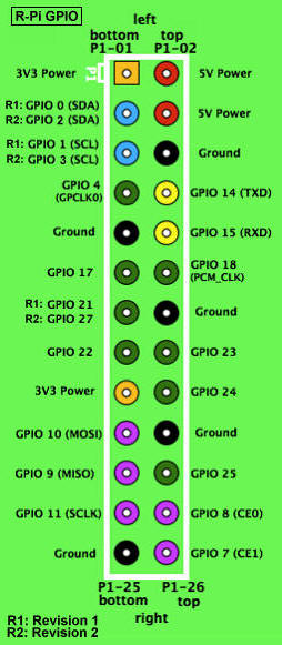
Description of the illustration gpio_layout.jpg
I2C
There is no static I2C configuration with the Raspberry Pi because there is no connected hardware. In comparison with SPI, I2C does not allow any communication with a loopback device.
| Device ID | Device Name | Mapped | Configuration |
|---|---|---|---|
| NONE | GPIO 2 (SDA)
GPIO 3 (SCL) |
Please note the following items about I2C on the Raspberry Pi.
-
I2CDevicePermissionis necessary. -
For revision 1 boards, I2C is provided by default on GPIO 0 and 1 (bus 0), and for revision 2 boards, I2C is provided on GPIO 2 and 3 (bus 1.)
-
The value of
DeviceConfig.DEFAULTwhen applied to thebusNumberis 0. -
The value of
DeviceConfig.DEFAULTwhen applied to theaddressSizeis 7. -
The
clockFrequencyfield is ignored. -
Before using I2C, you will have to load two I2C modules:
i2c-bcm2708andi2c-dev. Add the following two lines to the/etc/modulesfile and reboot to apply the changes.i2c-bcm2708 i2c-dev
MMIO
The following MMIO peripherals are available:
| Device ID | Device Name | Mapped | Configuration |
|---|---|---|---|
| 900 | PWM |
The MMIO peripherals include CTL, STA, RNG1, DAT1, and FIF1 registers (all of them are of type INT) with no event support.
Due to nature of memory organization of the Raspberry Pi, programmers can create a custom MMIODeviceConfig to access the memory range {0x20000000, 0x21000000}. Please note that not all addresses are accessible in the range and some of them may cause a board reboot. Please check the documentation for SFR addresses and its behavior. The end addresses are not inclusive.
SPI
The SPI has a single static configuration with the following parameters:
| Device ID | Device Name | Mapped | Configuration |
|---|---|---|---|
| 300 | SPI_Slave | GPIO10 (MOSI)
GPIO9 (MISO) GPIO11 (SCLK) GPIO8 (CE0) |
SPI bus number: 0 (SPI1)
Chip Enable: 0 (CE0/GPIO8) The number of bit of slave's word: 8 Clock frequency in Hz: 2000000 Clock polarity and phase: 1 (CPOL_Low, CPHA_2Edge) Bit ordering of the slave device: 1 (BIG_ENDIAN) |
Please note the following items about SPI on the Raspberry Pi.
-
The value of
DeviceConfig.DEFAULTwhen applied to thebusNumberis 0. -
The value of
DeviceConfig.DEFAULTwhen applied to theclockFrequencyis 2000000 Hz. -
The value of
DeviceConfig.DEFAULTwhen applied to thewordLengthis 8. -
The value of
DeviceConfig.DEFAULTwhen applied to thebitOrderingis 1 (big-endian). -
Before using SPI, you will have to load the SPI modules by running the following command:
$ modprobe spi_bcm2708, or by using the same method as I2C: uncomment the appropriate line in theetc/modprob.d/raspi-blacklist.conffile and reboot the board. -
Only 8-bit word lengths are supported on the Raspberry Pi board.
-
No real hardware is connected by default.
Note:
You can connect MISO and MOSI pins to get a simple loopback device for testing your code.UART
The following UART devices are preconfigured:
| Device ID | Device Name | Mapped | Configuration |
|---|---|---|---|
| 100 | UART | GPIO 14 (TXD)
GPIO 15 (RXD) |
controllerName = ttyAMA0
|
Please note the following items about UART on the Raspberry Pi.
-
By default, the Raspberry Pi uses the UART as a serial console. Before using UART, make sure that
/dev/ttyAMA0is not being used as a console. This can be done by changing the boot command line by editing the/boot/cmdline.txtfile and removing the line "console=ttyAMA0,115200 kgdboc=ttyAMA0,115200" from the boot arguments. Also, comment out the following line: "2:23:respawn:/sbin/getty -L ttyAMA0 115200 vt100" in the file/etc/inittab.In the case when the
/bootis mounted as a read-only partition, it must be remounted with write permissions to enable modifying thecmdline.txtfile.sudo mount -n -o remount,rw /boot
Then edit the
cmdline.txtfile and reboot the Raspberry Pi board. -
By default, the
piuser is in thedialoutgroup. That givespithe ability to access/dev/ttyAMA0(and, consequently, UART from Java) without administrator rights.

