7 Oracle JCA Adapter for AQ
This chapter describes how to use the Oracle JCA Adapter for AQ (Oracle AQ Adapter), which enables an Oracle BPEL Process Manager (Oracle BPEL PM) or an Oracle Mediator to interact with a single consumer or a multiconsumer queue.
This chapter includes the following sections:
7.1 Introduction to the Oracle AQ Adapter
Oracle Streams Advanced Queuing (AQ) provides a flexible mechanism for bidirectional, asynchronous communication between participating applications. Advanced queues are an Oracle database feature, and are therefore scalable and reliable. Other features of Oracle database, such as backup and recovery (including any-point-in-time recovery), logging, transactional services, and system management, are also inherited by advanced queues. Multiple queues can also service a single application, partitioning messages in a variety of ways and providing another level of scalability through load balancing.
This section includes the following sections:
-
Section 7.1.1, "Oracle AQ Adapter Integration with Oracle BPEL Process Manager"
-
Section 7.1.2, "Oracle AQ Adapter Integration with Oracle Mediator"
For more information on Oracle AQ, see "Introduction to Oracle Streams AQ" in the Oracle Streams Advanced Queuing User's Guide.
7.1.1 Oracle AQ Adapter Integration with Oracle BPEL Process Manager
JCA Binding Component is used for the bidirectional integration of the JCA 1.5 resource adapters with Oracle BPEL Process Manager. JCA Binding Component is based on standards and employs the Web service Invocation Framework (WSIF) technology for exposing the underlying JCA interactions as Web services.
For more information about Oracle AQ Adapter architecture, adapter integration with Oracle BPEL Process Manager, and adapter deployments, see Chapter 3, "Adapter Integration with Oracle Application Server Components."
7.1.2 Oracle AQ Adapter Integration with Oracle Mediator
The Mediator Server supports Oracle AQ Adapter and enables you to define inbound and outbound adapter services for each. An inbound adapter service receives data from an Oracle AQ Adapter and transforms it into an XML message. An outbound adapter service sends data to a target application by transforming an XML message into the native format of the given adapter.
Using the Mediator Server, you can send or receive messages from Oracle Advanced Queuing single or multiconsumer queues.
Note:
Oracle BPEL PM pre-dates Mediator and most of this guide and the samples implicitly assume use with Oracle BPEL PM. However, the Oracle AQ Adapter works equally well with either Oracle BPEL PM or Mediator. For any mention of Oracle BPEL PM here, you may substitute Mediator, instead.7.2 Oracle AQ Adapter Features
The Oracle AQ Adapter is both a producer and a consumer of AQ messages. The enqueue operation is exposed as a JCA outbound interaction. The dequeue operation is exposed as a JCA inbound interaction.
The Oracle AQ Adapter supports ADT (Oracle object type), XMLType, and RAW queues as payloads. It also supports extracting a payload from one ADT member column.
The Oracle AQ Adapter supports normalized properties for enqueue and dequeue operations.
For more information about the properties supported by Oracle AQ Adapter, see Appendix A, "Oracle AQ Adapter Properties."
You can obtain the Oracle AQ Adapter samples by accessing the Oracle SOA Sample Code site.
This section includes the following topics:
-
Section 7.2.1, "Enqueue-Specific Features (Message Production)"
-
Section 7.2.10, "Control Dequeue Timeout and Multiple Inbound Polling Threads"
7.2.1 Enqueue-Specific Features (Message Production)
The Oracle AQ Adapter supports the following features of Oracle Streams AQ:
-
In the Adapter Configuration Wizard, you can specify a correlation identifier when defining an enqueue operation, which you use to retrieve specific messages.
-
In Oracle Streams AQ, multiple consumers can process and consume a single message. To use this feature, you must create multiconsumer queues and enqueue the messages into these queues. In this configuration, a single message can be consumed by multiple AQ consumer (dequeue operation), either through the default subscription list or with an override recipient list. Under this scenario, a message remains in the queue until it is consumed by all of its intended consumer agents. The Oracle AQ Adapter enqueue header property (
jca.aq.RecipientList) enables you to specify the override recipient list (string values separated by commas) that can retrieve messages from a queue. All consumers that are added as subscribers to a multiconsumer queue must have unique values for theRecipientparameter. Two subscribers cannot have the same values for theNAME,ADDRESS, andPROTOCOLattributes. -
If you specify the priority of enqueued messages, then the messages are dequeued in priority order. If two messages have the same priority, then the order in which they are dequeued is determined by the enqueue time. You can also create a first-in, first-out (FIFO) priority queue by specifying the enqueue time priority as the sort order of the messages. This priority is a property of the Oracle AQ Adapter enqueue header. The enqueue time is set automatically by the underlying AQ application.
Here is an example of how to create the FIFO queue:
EXECUTE DBMS_AQADM.CREATE_QUEUE_TABLE( \
queue_table => 'OE_orders_pr_mqtab', \
sort_list =>'priority,enq_time', \
comment => 'Order Entry Priority \
MultiConsumer Orders queue table',\
multiple_consumers => TRUE, \
queue_payload_type => 'BOLADM.order_typ', \
compatible => '8.1', \
primary_instance => 2, \
secondary_instance => 1);
EXECUTE DBMS_AQADM.CREATE_QUEUE ( \
queue_name => 'OE_bookedorders_que', \
queue_table => 'OE_orders_pr_mqtab');
-
Time Specification and Scheduling
In Oracle Streams AQ, you can specify a delay interval and an expiration interval. The delay interval determines when an enqueued message is marked as available to the dequeuers after the message is enqueued. When a message is enqueued with a delay time set, the message is marked in a
WAITstate. Messages in aWAITstate are masked from the default dequeue calls. The expiration time property is used to specify an expiration time, and the message is automatically moved to an exception queue if the message is not consumed before its expiration.
7.2.2 Dequeue and Enqueue Features
Oracle Streams AQ provides the following dequeuing options:
-
Poll option
-
Notification option
The poll option involves processing the messages as they arrive and polling repeatedly for messages. The Oracle AQ Adapter supports a polling mechanism for consuming AQ messages.
The Oracle AQ Adapter supports the following features of Oracle Streams AQ:
-
Multiconsumer Queue
The Oracle AQ Adapter can retrieve messages from a multiconsumer queue.
-
Navigation of Messages for Dequeuing
Messages do not have to be dequeued in the same order in which they were enqueued. You can use a correlation identifier to specify dequeue order. The Adapter Configuration Wizard defines the correlation ID for the dequeue operation.
-
Retries with Delays
The number of retries is a property of the Oracle AQ Adapter dequeue header. If the number of retries exceeds the limit, then the message is moved to an exception queue that you specify. The exception queue is a property of the Oracle AQ Adapter enqueue header.
-
Rule-Based Subscription
Oracle Streams AQ provides content-based message filtering and subject-based message filtering. A rule defines one or more consumers' interest in subscribing to messages that conform to that rule. For a subject-based rule, you specify a Boolean expression using syntax similar to the
WHEREclause of a SQL query. This Boolean expression can include conditions on message properties (current priority and correlation ID), user data properties (object payloads only), and functions (as specified in theWHEREclause of a SQL query). -
Oracle AQ Adapter Header Properties
For more information about Oracle AQ Adapter header properties, see Appendix A, "Oracle AQ Adapter Properties."
-
Dequeue Condition
The Dequeue condition is an advanced queuing product feature that Oracle AQ Adapter uses. If a dequeue condition is specified and no messages meet the specified condition, then no dequeue happens.
A dequeue condition element is a Boolean expression using syntax similar to the
WHEREclause of a SQL query. This Boolean expression can include conditions on message properties, user object payload data properties, and PL/SQL or SQL functions. Message properties includepriority,corrid, and other columns in the queue table.When a dequeue is performed from a multisubscriber queue, it is sometimes necessary to screen the messages and accept only those that meet certain conditions. These conditions may concern header information, such as in selecting messages of only priority 1, or some aspect of the message payload, such as in selecting only loan applications above $100,000.
The Message Selector Rule field is displayed in Step 15 if you select a multisubscriber queue. Enter a subscription rule in the form of a Boolean expression using syntax similar to a SQL
WHEREclause, such aspriority = 1, orTAB.USER_DATA.amount > 1000. The adapter dequeues only those messages for which this Boolean expression is true.You must select the Access to non-payload fields also needed check box to access header information.
When this check box is selected, the generated WSDL file has additional code in the
typesection:<?xml version = '1.0' encoding = 'UTF-8'?> <?binding.jca Inbound_aq.jca?> <definitions name="Inbound" targetNamespace="http://xmlns.oracle.com/pcbpel/adapter/aq/Inbound/" xmlns="http://schemas.xmlsoap.org/wsdl/" xmlns:tns="http://xmlns.oracle.com/pcbpel/adapter/aq/Inbound/" xmlns:plt="http://schemas.xmlsoap.org/ws/2003/05/partner-link/" xmlns:obj1="http://xmlns.oracle.com/xdb/SCOTT" xmlns:imp1="http://www.oracle.com/ipdemo/"> <types> <schema attributeFormDefault="qualified" elementFormDefault="qualified" targetNamespace="http://xmlns.oracle.com/pcbpel/adapter/aq/Inbound/" xmlns="http://www.w3.org/2001/XMLSchema" xmlns:tns="http://xmlns.oracle.com/pcbpel/adapter/aq/Inbound/" xmlns:hdr="http://xmlns.oracle.com/pcbpel/adapter/aq/inbound/" xmlns:obj1="http://xmlns.oracle.com/xdb/SCOTT"> <import namespace="http://xmlns.oracle.com/xdb/SCOTT" schemaLocation="xsd/SCOTT_MAGAZINE_TYPE.xsd"/> <import namespace="http://xmlns.oracle.com/pcbpel/adapter/aq/inbound/" schemaLocation="xsd/aqAdapterInboundHeader.xsd"/> <complexType name="HeaderCType"> <sequence> <element name="QueueHeader" type="hdr:HeaderType"/> <element name="PayloadHeader" type="obj1:MAGAZINE_TYPE"/> </sequence> </complexType> <element name="Header" type="tns:HeaderCType"/> </schema> <schema xmlns="http://www.w3.org/2001/XMLSchema"> <import namespace="http://www.oracle.com/ipdemo/" schemaLocation="xsd/simpleMagazine.xsd"/> </schema> </types> <message name="simpleMagazine_msg"> <part name="simpleMagazine" element="imp1:simpleMagazine"/> </message> <message name="Header_msg"> <part name="Header" element="tns:Header"/> </message> <portType name="Dequeue_ptt"> <operation name="Dequeue"> <input message="tns:simpleMagazine_msg"/> </operation> </portType> <plt:partnerLinkType name="Dequeue_plt"> <plt:role name="Dequeue_role"> <plt:portType name="tns:Dequeue_ptt"/> </plt:role> </plt:partnerLinkType> </definitions>Note that
PayloadHeaderis the type for the whole ADT of the queue. The payload contains only the chosen payload field. If you selected Access to non-payload fields also needed, then thePayloadHeader(. jca.aq.HeaderDocument) contains the whole ADT (including the payload field, which is also present in the header, but ignored by the adapter.)For more information about Oracle AQ Adapter architecture, adapter integration with Oracle BPEL Process Manager, and adapter deployments, see Chapter 1, "Introduction to Oracle JCA Adapters."
7.2.3 Supported ADT Payload Types
The Oracle AQ Adapter supports the following RAW types:
-
BLOB -
CHAR -
CLOB -
DATE -
DECIMAL -
DOUBLE PRECISION -
FLOAT -
INTEGER -
NUMBER -
REAL -
SMALLINT -
TIMESTAMP -
VARCHAR2
In addition to the RAW types mentioned in the preceding list, the Oracle AQ Adapter supports primitive types and varrays of objects.
Note:
The Oracle AQ Adapter does not currently support the following data types for ADT columns:TIMESTAMP WITH LOCAL TIMEZONE and TIMESTAMP WITH TIMEZONE.If you choose a payload field instead of the whole ADT, then choose one of the following data types as the payload field:
-
CLOB, either XSD or opaque schema -
VARCHAR2, either XSD or opaque schema -
BLOB, opaque schema only -
XMLTYPE, either XSD or opaque schema
7.2.4 Native Format Builder Wizard
JDeveloper BPEL Designer provides the Native Format Builder Wizard to define XSD files of various formats, including for the AQ RAW payload.
For more information about the Native Format Builder wizard, see Chapter 6, "Native Format Builder Wizard."
To obtain sample code that demonstrates usage of the Native Format Builder access the Oracle SOA Sample Code site.
The payload schemas depend on the payload type. In the whole ADT case, the schema is completely generated by the Adapter Configuration Wizard. In an ADT case where the payload case selected is BLOB, an opaque schema as defined in the following example must be used:
<element name="opaqueElement" type="base64Binary" />
In all other cases, you can either provide a schema or use an opaque schema, as shown in Table 7-1.
| Payload Type | Supported Schema |
|---|---|
|
|
User-provided schema or opaque schema. |
|
Whole |
Must use a schema generated by the Adapter Configuration Wizard, which is based on the queue structure. |
|
|
User-provided schema or opaque schema. |
|
|
User-provided schema or opaque schema. |
|
|
Opaque schema. |
|
|
User-provided schema or opaque schema. |
If you do not have an XSD file but the payload data is formatted (for example, in a comma-delimited value (CSV) format), you can use the Native Format Builder wizard to generate an appropriate XSD. The Adapter Configuration Wizard is integrated with the Native Format Builder wizard. In the Adapter Configuration Wizard Messages window, click Define Schema for Native Format to access the Native Format Builder wizard.
7.2.5 Normalized Message Support
Header manipulation and propagation is a key business integration messaging requirement. Oracle BPEL PM, Mediator, Oracle JCA, and B2B rely extensively on header support to solve customers' integration needs. For example, you can preserve a file name from the source directory to the target directory by propagating it through message headers. In Oracle BPEL PM and Mediator, you can access, manipulate, and set headers with varying degrees of UI support.
Note:
AQ Adapter inbound and outbound headers supported in the 10.1.3 release are supported in 11g through normalized message properties.For more information, see Section 2.14, "Correlation Support Within Adapters"
Propagating Headers in a Normalized Message:
A normalized message is simplified to have only two parts, properties and payload.Typically, properties are name-value pairs of scalar types. To fit the existing complex headers into properties, properties are flattened into scalar types.
Manipulating Headers in Design Time:
The user experience is simplified while manipulating headers in design time, because the complex properties are predetermined. In the Mediator or BPEL designer, you can manipulate the headers with some reserved key words. For example, currently in Mediator, you can access an inbound File adapter, fileName header using the following expression:
$nmproperty.InboundFileHeaderType.fileName
However, this method does not address the properties that are dynamically generated based on your input. For example, in the AQ Adapter Wizard, you can propagate some fields from an AQ object as headers. Based on your choice, the header definitions are defined. These definitions are not predetermined and hence cannot be accounted for in the list of predetermined property definitions. You cannot design header manipulation of the dynamic properties before they are defined. To address this limitation, you must generate all the necessary services (composite entry points) and references. This restriction applies to services that are expected to generate dynamic properties. Once dynamic properties are generated, they must be stored for each composite. Only then you can manipulate the dynamic properties in Mediator or BPEL designer.
Identifying Properties That Must Be Propagated over the Life Cycle of the Normalized Message:
Some properties must be propagated across the life cycle of the message, whereas some must not be propagated. The properties that must be propagated are referred to as propagatable properties, whereas properties that must not be propagated are referred to as non-propagatable properties.
7.2.6 Is DOM 2 Compliant
Oracle AQ Adapter is Document Object Model Level 2 (DOM 2) compliant, that is, the AQ adapter can generate document objects that are compliant with DOM2 specification.
7.2.7 Is Message-Size Aware
Oracle AQ Adapter is message-size aware, that is, Oracle AQ Adapter calculates the message size and reports the size back to JCA Binding Component. The API, related to size, exposed by JCA Binding Component can be used for reporting purposes.
7.2.8 Multiple Receiver Threads
Oracle AQ Adapter supports an activation endpoint property, "adapter.aq.dequeue.threads". Setting this property is a preferred way to spawn multiple threads for the inbound message flow between the adapter and the Enterprise Information System (EIS). Earlier versions of the Oracle AQ Adapter relied on the activationInstances endpoint property, which was used by JCA Binding Component to initiate multiple endpoints.
7.2.9 DequeueTimeout Property
The DequeueTimeOut property supports multiple inbound dequeue threads. The value for this property determines how many seconds the dequeue() API waits for messages before it returns and the next polling cycle begins.
Add this property to the composite.xml file, as shown in the following example:
<service name="Inbound" ui:wsdlLocation="Inbound.wsdl">
<interface.wsdl interface="http://xmlns.oracle.com/pcbpel/adapter/aq/AQ_InboundRetry_Mediator/AQ2JMSInboundRetry/Inbound%2F#wsdl.interface(Dequeue_ptt)"/>
<binding.jca config="Inbound_aq.jca">
<property name="DequeueTimeOut" type="xs:integer" many="false"override="may">10
</property>
</binding.jca>
</service>
7.2.10 Control Dequeue Timeout and Multiple Inbound Polling Threads
Oracle AQ Adapter provides system properties to control dequeue timeout and multiple inbound polling threads for each Java Virtual Machine (JVM), systemwide, instead of for each process.
The system property provided by Oracle AQ Adapter to control dequeue timeout is oracle.adapter.aq.wait, and the property that controls inbound polling threads is adapter.aq.dequeue.threads.
7.2.11 Stream Payload Support
Oracle AQ Adapter provides support to stream payload. When you enable this feature, the payload is streamed to a database instead of getting manipulated in SOA run time as in a memory DOM. You use this feature while handling large payloads. To enable support to stream payload, you must select the Enable Streaming check box while defining the dequeue operation parameters in Oracle JDeveloper (JDeveloper). When you select the Enable Streaming check box, a corresponding Boolean property EnableStreaming is appended to the ActivationSpec properties defined in the respective .jca file, as shown in the following example. If the EnableStreaming property does not exist, then the default value false is assumed. The property is applicable when processing Raw messages, XMLType messages, and ADT type messages for which a payload is specified though an ADT attribute.
<activation-spec className="oracle.tip.adapter.aq.inbound.AQDequeueActivationSpec">
      <property name="QueueName" value="RAW_IN_QUEUE"/>
      <property name="DatabaseSchema" value="SCOTT"/>
      <property name="EnableStreaming" value="true"/>
</activation-spec>
7.2.12 Oracle AQ Adapter Inbound Retries
If you configure the Oracle AQ Adapter inbound retries to retry for more than 5 times by using the jca.retry.count service binding property for a retryable exception, then ensure that the queue is created with max_retries value that is greater then the value used for jca.retry.count. If nothing is specified, then the queue is created with a max_retries value of 5 which would mean that the message ends up in the exception queue after 5 retries and is not be delivered to adapter for further processing. If jca.retry.count is specified with a value of 5 or less, then you do not have to change the queue max_retries property.
Use the following code to change the max_retries property when creating a queue:
begin
DBMS_AQADM.CREATE_QUEUE_TABLE ( queue_table => 'RAW_IN_QUEUE_TABLE',queue_payload_type => 'RAW');
DBMS_AQADM.CREATE_QUEUE ( queue_name => 'RAW_IN_QUEUE',queue_table=> 'RAW_IN_QUEUE_TABLE', max_retries=>1500);
DBMS_AQADM.START_QUEUE ( queue_name => 'RAW_IN_QUEUE');
DBMS_AQADM.CREATE_QUEUE_TABLE ( queue_table => 'RAW_OUT_QUEUE_TABLE', queue_payload_type => 'RAW');
DBMS_AQADM.CREATE_QUEUE ( queue_name  => 'RAW_OUT_QUEUE', queue_table => 'RAW_OUT_QUEUE_TABLE');
DBMS_AQADM.START_QUEUE ( queue_name => 'RAW_OUT_QUEUE');
end;
7.2.13 Error Handling Support
For information about error handling, see Section 2.21, "Error Handling."
7.2.14 Performance Tuning
Oracle AQ Adapter supports performance tuning features.
For more information, see "Oracle AQ Adapter Tuning" in the Oracle Fusion Middleware Performance and Tuning Guide.
7.3 Deployment
The Oracle AQ Adapter comes deployed to the application server as part of the install. It contains a single adapter instance entry eis/AQ/aqSample, which points to the data source jdbc/aqSample. The data source is not created as part of install and must be created manually. The connection information to the database is inside the data source definition.
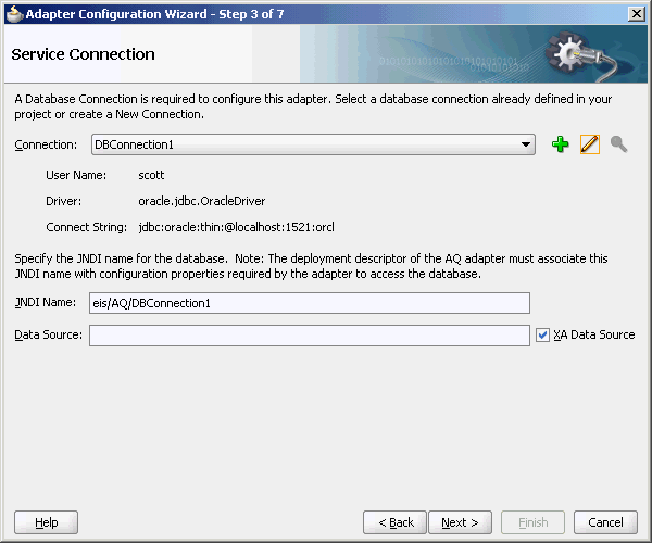
When deploying a SOA project that uses the Oracle AQ Adapter instance eis/AQ/aqSample that exists at the time of installation, you must first create a data source at jdbc/aqSample. On the other hand, if a new adapter instance is preferred, then you must add a new adapter instance and restart the application server. This is because you want to point to a data source other than the one referred in the existing adapter instance jdbc/aqSample, or because you chose a name for the adapter instance that does not yet exist. For instance, if you create a connection in JDeveloper named DBConnection1, then by default the AQ Adapter service points to eis/AQ/DBConnection1, as shown in Figure 7-6.
You can also check which adapter instance the service is pointing to by looking at the .jca file, as shown in the following code snippet:
<connection-factory location="eis/AQ/aqSample" … />
In the preceding example, the location is the JNDI name of the adapter instance at run time.
You can create a new AQ Adapter instance through the Oracle WebLogic Server Administration Console, as mentioned in Section 2.18, "Adding an Adapter Connection Factory" or by directly editing the weblogic-ra.xml file. The following are the steps to edit weblogic-ra.xml:
-
Search
fmwhome/ forAqAdapter.rar. -
Unzip the file.
-
Edit
META-INF/weblogic-ra.xml(and possiblyra.xml.) -
Jar the file again.
-
Restart the application server.
The following is a sample adapter instance in weblogic-ra.xml:
<connection-instance>
  <jndi-name>eis/AQ/aqSample</jndi-name>
  <connection-properties>
    <properties>
      <property>
         <name>XADataSourceName</name>
         <value>jdbc/aqSample</value>
      </property>
      <property>
    <name>DataSourceName</name>
    <value></value>
      </property>
      <property>
    <name>ConnectionString</name>
    <value></value>
      </property>
      <property>
    <name>UserName</name>
    <value></value>
      </property>
      <property>
    <name>Password</name>
    <value></value>
      </property>
      <property>
    <name>DefaultNChar</name>
    <value>false</value>
      </property>
      <property>
    <name>UseDefaultConnectionManager</name>
    <value>false</value>
      </property>
    </properties>
  </connection-properties>
</connection-instance>
The mandatory properties are: jndi-name, XADataSourceName or DataSourceName. The jndi-name property must match the location attribute in the .jca file, and is the name of the adapter instance. The XADataSourceName or DataSourceName property is the name of the underlying data source (which has the connection information). Specify one of the properties XADataSourceName or DataSourceName. The usage depends on if the scenario involves and would require adapter to participate in global transaction or if local transaction semantics are sufficient. In the former case XADataSourceName must be specified while in the latter case DataSourceName must be specified. When specifying XADataSourceName property ensure that the physical data source it refers to is XA enabled while when specifying DataSourceName property the physical data source it refers to might or might not be XA enabled.
The following are the two most common mistakes with deployment:
-
Not creating an adapter instance entry that matches the location attribute in your
.jcafile (or not creating one at all.) -
Setting the location attribute in the
.jcafile to the name of the data source directly.
For the latter, there is a level of indirection in that you give the name of the adapter instance (eis/AQ/...), which itself points to the data source pool (jdbc/...). It is a common mistake to miss this indirection and give the name jdbc/... directly in the location attribute.
Additional Adapter Instance Properties
There are additional properties in the AQ Adapter instance beyond xADataSourceName, dataSourceName.
For information about the Oracle AQ Adapter instance properties, see Appendix A, "Oracle AQ Adapter Properties."
7.4 Oracle AQ Adapter Use Cases
This section includes the following topics:
7.4.1 Generic Use Case
The following use cases include a general walkthrough of the Adapter Configuration Wizard, followed by examples of how you can modify the general procedure in different situations. Each example shows relevant parts of the generated WSDL and JCA files.
This section includes the following topics:
-
Section 7.4.1.1, "The Adapter Configuration Wizard Walkthrough"
-
Section 7.4.1.2, "Dequeuing and Enqueuing Object and ADT Payloads"
-
Section 7.4.1.3, "Dequeuing One Column of the Object Payload"
-
Section 7.4.1.4, "Configuring the Enqueue/Dequeue Operation Type"
-
Section 7.4.1.5, "Using Correlation ID for Filtering Messages During Dequeue"
-
Section 7.4.1.6, "Enqueuing and Dequeuing from Multisubscriber Queues"
7.4.1.1 The Adapter Configuration Wizard Walkthrough
In this example, you create an Oracle AQ Adapter service that dequeues messages to the service_in_queue queue, with a payload that is one field within the service_type object, and with a user-defined schema.
This section describes the tasks required to configure Oracle AQ Adapter by using the Adapter Configuration Wizard in JDeveloper.
This section includes the following topics:
7.4.1.1.1 Meeting Prerequisites
This example assumes that you are familiar with basic BPEL constructs, such as activities and partner links, and JDeveloper environment for creating and deploying BPEL composite.
You must have access to a database with the SCOTT schema.
To perform this use case, you require the following files from the artifacts.zip file contained in the adapters-aq-103-adtclobpayload sample:
-
artifacts/sql/setup_user.sql -
artifacts/sql/create_type_service.sql -
artifacts/sql/create_queues.sql -
artifacts/sql/dequeue_service.sql -
artifacts/sql/enqueue_service.sql
To obtain the adapters-aq-103-adtclobpayload sample, access the Oracle Sample SOA Code site.
7.4.1.1.2 Creating an Application and an SOA Project
You must create a JDeveloper application to contain the SOA composite. Perform the following steps to create an application, a SOA project:
-
Open JDeveloper.
-
In the Application Navigator, click New Application. The Create Generic Application Name your application page is displayed, as shown in Figure 7-1.
-
Enter a name for the application in the Application Name field.
-
In the Application Template list, choose Generic Application.
Figure 7-1 The Create Generic Application Name your application Page
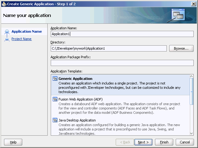
Description of "Figure 7-1 The Create Generic Application Name your application Page"
-
Click Next.
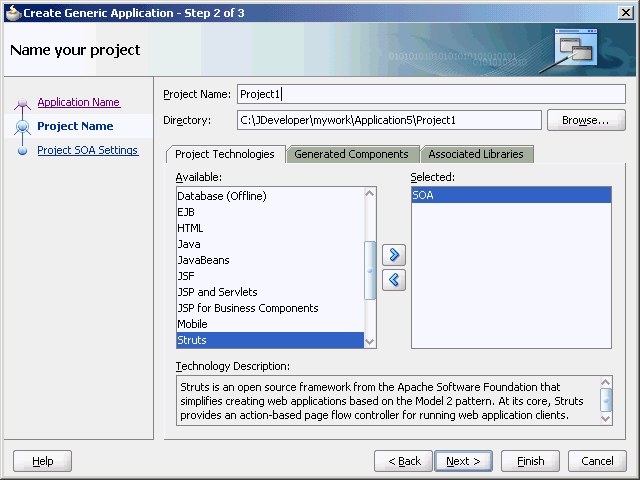
The Create Generic Application Name your project page is displayed, as shown in .
-
In the Project Name field, enter a descriptive name.
For example,
SOAComposite. -
In the Available list in the Project Technologies tab, double-click SOA to move it to the Selected list.
Figure 7-2 The Create Generic Application Name your Generic project Page
Description of "Figure 7-2 The Create Generic Application Name your Generic project Page"
-
Click Next.
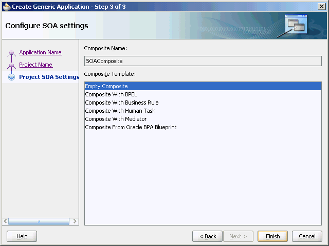
The Create Generic Application Configure SOA settings page is displayed, as shown in Figure 7-3.
Figure 7-3 The Create Generic Application Configure SOA settings Page
Description of "Figure 7-3 The Create Generic Application Configure SOA settings Page"
-
Select Composite With BPEL from the Composite Template list, and then click Finish.
You have created a new application and an SOA project. This automatically creates an SOA composite.
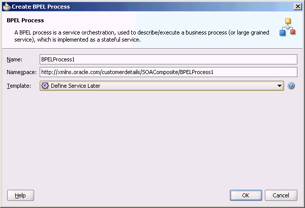
The Create BPEL Process page is displayed, as shown in Figure 7-4.
-
Enter a name for the BPEL process in the Name field. For example,
CustomerDetails. -
Select Define Service Later in the Template list, and then click OK.
You have created the
CustomerDetailsBPEL process.
7.4.1.1.3 Defining an Oracle AQ Adapter Service
The next step is to define an Oracle AQ Adapter service. Perform the following steps to create an Oracle AQ Adapter service:
-
In the Component Palette, select SOA.
-
Drag and drop AQ Adapter from the Service Adapters list to the Exposed Services swim lane in the composite.xml page.
The Adapter Configuration Wizard Welcome page is displayed.
-
Click Next.
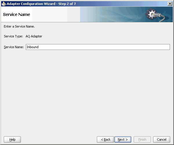
The Adapter Configuration Wizard Service Name page is displayed, as shown in Figure 7-5.
Figure 7-5 The Adapter Configuration Wizard Service Name Page
Description of "Figure 7-5 The Adapter Configuration Wizard Service Name Page"
-
Specify a service name, and then click Next.
The Adapter Configuration Wizard Service Connection page is displayed, as shown in Figure 7-6.
Figure 7-6 Adapter Configuration Wizard Service Connection Page
Description of "Figure 7-6 Adapter Configuration Wizard Service Connection Page"
-
Click the plus icon to create a database connection.
The Create Database Connection page is displayed.
Note:
You must connect to the database where Oracle Applications is running. -
Enter the following information:
-
For Create Connection In, choose Application Resources.
-
In the Connection Name field, specify a unique name for the database connection.
In this example, type DBConnection1.
-
From the Connection Type box, select Oracle (JDBC).
-
In the UserName field, specify the user name to be authorized for access to the database.
In this example, type
scott. -
In the Role field, enter a role, if applicable.
This must be a specific database role, such as
SYSDBA, as defined in the database. This field is optional. In this example, leave the Role field blank. -
In the Password field, specify the password to be associated with the specified user name.
In this example, type
tiger. -
Select Save Password and Deploy Password.
-
From the Driver list, select Thin.
-
In the Host Name field, enter a value to identify the computer running the Oracle server.
Use an IP address or a host name that can be resolved by TCP/IP, for example,
myserver. The default value islocalhost. -
In the JDBC Port field, enter a value to identify the TCP/IP port. The default is
1521. -
In the SID field, enter a value for the unique system identifier (SID) of an Oracle database instance.
The default is
XE. -
Click Test Connection to determine whether the specified information establishes a connection with the database.
A Success message is displayed.
-
Click OK.
The Connection you created is displayed in the Connection field in the Service Name page.
Notice that the Java Naming and Directory Interface (JNDI) name in the JNDI Name field is populated after you have created the database connection. The JNDI name acts as a placeholder for the connection used when your service is deployed to the BPEL server. Using JNDI as a placeholder enables you to use different databases for development and later production.
The value specified in the JNDI name must exist in the Oracle AQ Adapter
weblogic-ra.xmlfile to ensure that the adapter runs in managed mode. A default connection instanceeis/AQ/aqSampleis shipped and can be used as the default value for this field. To use this connection instance, it would still require that a data source is created with the JNDI namejdbc/aqSample.
-
-
Click Next.
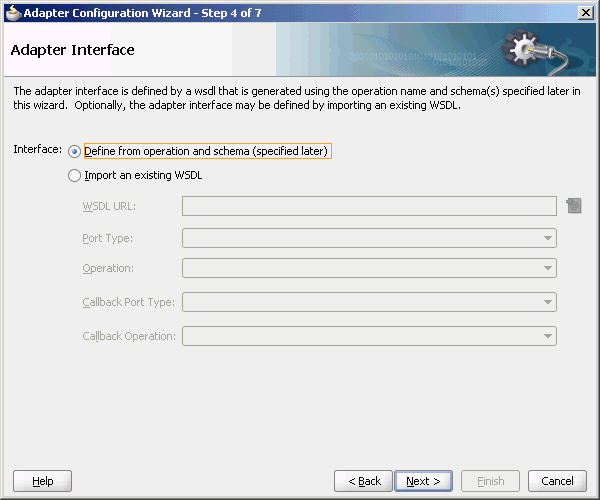
The Adapter Configuration Wizard Adapter Interface page is displayed, as shown in Figure 7-7.
-
In the Adapter Interface page, choose Define from operation and schema (specified later).
Figure 7-7 The Adapter Configuration Wizard Adapter Interface Page
Description of "Figure 7-7 The Adapter Configuration Wizard Adapter Interface Page"
-
Click Next.
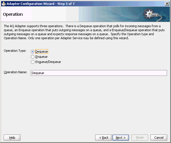
The Operation page is displayed.
-
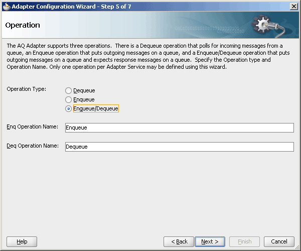
Oracle AQ Adapter supports three operations:
-
Dequeue: Polls for incoming messages from a queue.
-
Enqueue: Puts outgoing messages in a queue.
-
Enqueue/Dequeue: Puts outgoing messages in a queue and expects response messages in a queue.
In this example, select Dequeue, as shown in Figure 7-8.
The operation is automatically named after the operation that you selected. However, you can edit the Operation Name field.
Figure 7-8 The Adapter Configuration Wizard Operation Page
Description of "Figure 7-8 The Adapter Configuration Wizard Operation Page"
Note:
When creating an SOA composite that uses Oracle AQ Adapter with ADT data type if theSchemaValidationproperty is set toTRUE, then anyNULLdata type in dequeue message results inAQ_INVALID_PAYLOADerror further resulting in message rejection. To avoid message rejection, you must set theSchemaValidationproperty tofalse. -
-
Click Next.
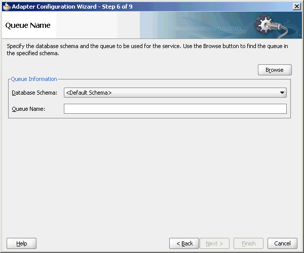
The Adapter Configuration Wizard Queue Name page is displayed, as shown in Figure 7-9.
Figure 7-9 The Adapter Configuration Wizard Queue Name Page
Description of "Figure 7-9 The Adapter Configuration Wizard Queue Name Page"
-
Select a database schema from the Database Schema list, or click Browse to browse for the schema. In this example, click Browse.
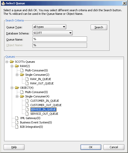
The Select Queue dialog is displayed, as shown in Figure 7-10.
-
Select the required queue, and then click OK.
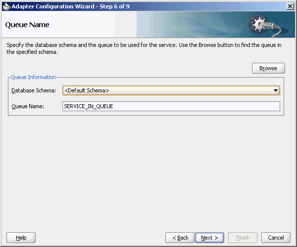
In this example, select SERVICE_IN_QUEUE. The Queue Name page is displayed again with the Queue Name field populated with SERVICE_IN_QUEUE, as shown in Figure 7-11.
Figure 7-11 The Adapter Configuration Wizard Queue Name Page
Description of "Figure 7-11 The Adapter Configuration Wizard Queue Name Page"
-
Click Next.
The Adapter Configuration Wizard Queue Parameters page is displayed, as shown in Figure 7-12.
Figure 7-12 The Adapter Configuration Wizard Queue Parameters Page
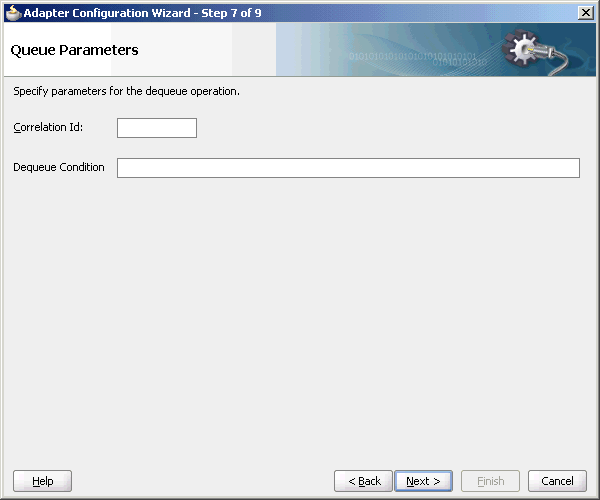
Description of "Figure 7-12 The Adapter Configuration Wizard Queue Parameters Page"
-
Enter values for the parameters, and then click Next.
-
Correlation ID: Enter an optional correlation ID from 1 to 30 characters in length. This is used to identify messages that can be retrieved at a later time by a dequeue activity using the same correlation ID.
The value to enter is agreed upon between the enqueuing sender and the dequeuing receiver for asynchronous conversations. The correlation ID maps to an AQ header property. Correlation IDs in the inbound direction enable you to be selective about the message to dequeue. This field is optional. If you do not enter a value, then all the messages in the queue are processed.
If you enter a value for the Correlation ID in the outbound direction, then all outbound messages have the correct ID set to the value entered. You can override this value on a per message basis in the correlation field of the outbound header.
-
Dequeue Condition: Displayed only when you select dequeue in the Operation page.
Enter a Boolean expression similar to the
WHEREclause of aSQLquery. This expression can include conditions on message properties, user data properties (object payloadsonly), and PL/SQL or SQL functions. If more than one message satisfies the dequeue condition, then the order of dequeuing is indeterminate, and the sort order of the queue is not honored.This field is displayed for inbound single consumer and multiconsumer queues.
-
-
Click Next.
The Adapter Configuration Wizard Object Payload page is displayed, as shown in Figure 7-13.
Figure 7-13 The Adapter Configuration Wizard Object Payload Page
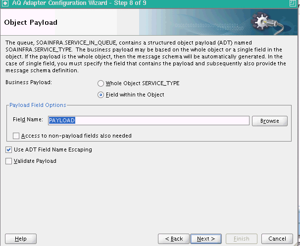
Description of "Figure 7-13 The Adapter Configuration Wizard Object Payload Page"
-
In Business Payload, select Field within the Object.
-
Click Browse in the Payload Fields Options section to select a field that contains the business payload.
The Select Payload Field dialog is displayed, as shown in Figure 7-14.
Figure 7-14 The Select Payload Field Dialog
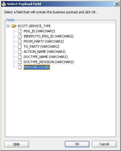
Description of "Figure 7-14 The Select Payload Field Dialog"
-
-
Select a field, and then click OK.
In this example, select PAYLOAD (CLOB).
The Object Payload field is displayed with all the payload details filled up, as shown in Figure 7-15.
Figure 7-15 The Adapter Configuration Wizard Object payload Page
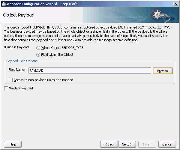
Description of "Figure 7-15 The Adapter Configuration Wizard Object payload Page"
-
Select Access to non-payload fields also needed, and then click Next.
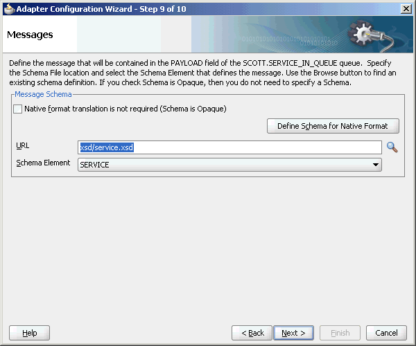
The Messages page is displayed.
The Message page has the following options:
-
Native format translation is not required (Schema is Opaque): Select this option if you do not want to specify a schema. Selecting this option disables all the other fields under Message Schema.
-
Define Schema for Native Format: Click this to start the Native Format Builder wizard, which guides you through the process of defining the native format.
-
URL: You can enter the path for the schema file URL or click Browse to browse for the path.
-
Schema Element: The name of the schema element.
-
-
In this example, click the Browse for schema file icon to browse for the schema file URL.
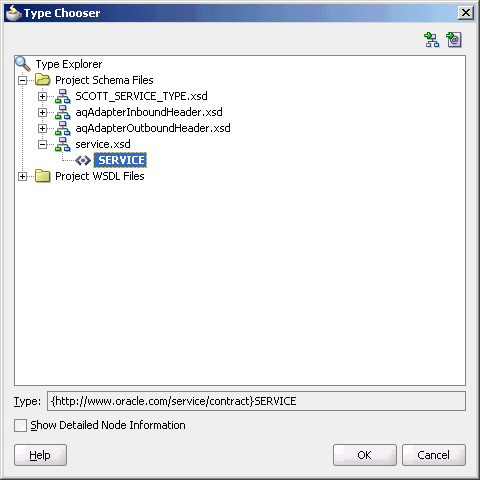
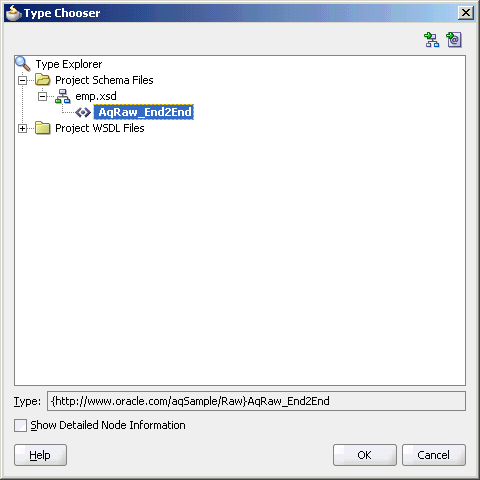
The Type Chooser dialog is displayed, as shown in Figure 7-16.
-
Select SERVICE from the list, as shown in Figure 7-16, and then click OK.
The Messages page reappears, with the Schema Location and Schema Element fields populated, as shown in Figure 7-17.
Figure 7-17 The Adapter Configuration Wizard Messages Page
Description of "Figure 7-17 The Adapter Configuration Wizard Messages Page"
-
Click Next.
The Finish screen is displayed. This page shows the path and name of the adapter file that the wizard creates.
-
Click Finish.
You have created an AQ Adapter service with dequeue operation.
-
Click OK.
7.4.1.1.4 Generated WSDL and JCA Files
The adapter service generates a WSDL and a JCA file to serve as the defined adapter interface.
The following is the WSDL file generated for the dequeue operation:
<definitions name="Inbound" targetNamespace="http://xmlns.oracle.com/pcbpel/adapter/aq/Inbound/" xmlns="http://schemas.xmlsoap.org/wsdl/" xmlns:tns="http://xmlns.oracle.com/pcbpel/adapter/aq/Inbound/" xmlns:plt="http://schemas.xmlsoap.org/ws/2003/05/partner-link/" xmlns:obj1="http://xmlns.oracle.com/xdb/SCOTT" xmlns:imp1="http://www.oracle.com/service/contract/">
    <types>
    <schema attributeFormDefault="qualified" elementFormDefault="qualified" targetNamespace="http://xmlns.oracle.com/pcbpel/adapter/aq/Inbound/" xmlns="http://www.w3.org/2001/XMLSchema" xmlns:tns="http://xmlns.oracle.com/pcbpel/adapter/aq/Inbound/" xmlns:hdr="http://xmlns.oracle.com/pcbpel/adapter/aq/inbound/" xmlns:obj1="http://xmlns.oracle.com/xdb/SCOTT">
       <import namespace="http://xmlns.oracle.com/xdb/SCOTT" schemaLocation="xsd/SCOTT_SERVICE_TYPE.xsd"/>
        <import namespace="http://xmlns.oracle.com/pcbpel/adapter/aq/inbound/" schemaLocation="xsd/aqAdapterInboundHeader.xsd"/>
            <complexType name="HeaderCType">
                <sequence>
                    <element name="QueueHeader" type="hdr:HeaderType"/>
                    <element name="PayloadHeader" type="obj1:SERVICE_TYPE"/>
                </sequence>
            </complexType>
            <element name="Header" type="tns:HeaderCType"/>
        </schema>
        <schema xmlns="http://www.w3.org/2001/XMLSchema">
            <import namespace="http://www.oracle.com/service/contract/" schemaLocation="xsd/service.xsd"/>
        </schema>
    </types>
    <message name="SERVICE_msg">
        <part name="SERVICE" element="imp1:SERVICE"/>
    </message>
    <message name="Header_msg">
        <part name="Header" element="tns:Header"/>
    </message>
    <portType name="Dequeue_ptt">
        <operation name="Dequeue">
            <input message="tns:SERVICE_msg"/>
        </operation>
    </portType>
    <plt:partnerLinkType name="Dequeue_plt">
        <plt:role name="Dequeue_role">
            <plt:portType name="tns:Dequeue_ptt"/>
        </plt:role>
    </plt:partnerLinkType>
</definitions>
7.4.1.2 Dequeuing and Enqueuing Object and ADT Payloads
Dequeuing and enqueuing is covered in Section 7.4.2, "Oracle AQ Adapter ADT Queue".
To enqueue or dequeue the entire object as the payload, perform the following:
For a working example of an ADT payload use case, refer to any of the following samples:
-
adapters-aq-102-adt -
adapters-aq-110-supportedadttypes
You can obtain these samples by accessing the Oracle SOA Sample Code site.
Note:
If you modify an ADT type using evolution commands such as ALTER OBJECT, the AQ Adapter will throw an ORA-25215 SQL exception.The workaround to this exception is to use only CREATE OBJECT (without issuing evolution commands such as ALTER OBJECT) to add attributes to the ADT TYPES.
7.4.1.3 Dequeuing One Column of the Object Payload
The walkthrough is an example of dequeuing one field or column within an object payload.
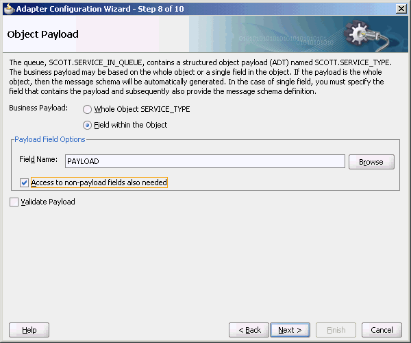
To create an Oracle AQ Adapter that dequeues one field in an object, you must perform the following steps in the Adapter Configuration Wizard Object Payload page:
-
Select Field within the Object.
-
Click Browse at the end of the Field Name field.
The Select Payload Field dialog is displayed.
-
Select a field that contains the business payload, and then click OK.
The Adapter Configuration Wizard Object Payload page with Field Name field populated with the field that you selected is displayed, as shown in Figure 7-18.
Figure 7-18 The Adapter Configuration Wizard Object Payload Page
Description of "Figure 7-18 The Adapter Configuration Wizard Object Payload Page"
-
Select Access to non-payload fields also needed, and then click Next.
The following segment of the generated JCA file specifies that one field, in this case the field named PAYLOAD, is dequeued in addition to payload header fields.
<adapter-config name="Inbound" adapter="AQ Adapter" xmlns="http://platform.integration.oracle/blocks/adapter/fw/metadata">
    <connection-factory location="eis/AQ/aqSample" UIConnectionName="Connection1" adapterRef=""/>
  <endpoint-activation portType="Dequeue_ptt" operation="Dequeue">
    <activation-spec className="oracle.tip.adapter.aq.inbound.AQDequeueActivationSpec">
      <property name="QueueName" value="SERVICE_IN_QUEUE"/>
      <property name="ObjectFieldName" value="PAYLOAD"/>
      <property name="PayloadHeaderRequired" value="true"/>
      <property name="SchemaValidation" value="false"/>
    </activation-spec>
  </endpoint-activation>
</adapter-config>
For a working example of an ADT CLOB use case where one field or column within an object payload is dequeued, refer to the following samples:
-
adapters-aq-103-adtclobpayload -
adapters-aq-105-adtclobopaquepayload
You can obtain these samples by accessing the Oracle SOA Sample Code site.
7.4.1.4 Configuring the Enqueue/Dequeue Operation Type
This use case walks you through the procedure for configuring the Enqueue/Dequeue operation type of the Oracle AQ Adapter, which lets the Oracle AQ Adapter put outgoing messages on a queue and expect response messages on a different queue.
This section includes the following topics:
-
Section 7.4.1.4.2, "Creating an Application and an SOA Project"
-
Section 7.4.1.4.6, "Monitoring Using the Fusion Middleware Control Console"
7.4.1.4.1 Meeting Prerequisites
To perform this use case, you must have access to a database with the SCOTT schema. Also, you require the following files from the artifacts.zip file contained in the adapters-aq-104-requestreply sample:
-
create_queues.sql -
drop_queues.sql -
enqueue.sql -
SendReply.sql -
setup_user.sql
To obtain the adapters-aq-104-requestreply sample code, access the Oracle SOA Sample Code site.
7.4.1.4.2 Creating an Application and an SOA Project
You must create a JDeveloper application to contain the SOA composite. Follow the steps documented in Section 7.4.1.1.2, "Creating an Application and an SOA Project" to create an application, and an SOA project.
7.4.1.4.3 Defining an Oracle AQ Adapter Service
Perform the following steps to create an Oracle AQ Adapter service to put outgoing messages on a queue and expect response messages on a queue:
-
In the Component Palette, select SOA.
-
Drag and drop AQ Adapter from the Service Adapters list to the Exposed Services swim lane in the composite.xml page.
The Adapter Configuration Wizard Welcome page is displayed.
-
Click Next.
The Adapter Configuration Wizard Service Name page is displayed, as shown in Figure 7-5.
-
Specify a service name, and then click Next.
The Adapter Configuration Wizard Service Connection page is displayed.
-
Click the plus icon to create a database connection.
The Create Database Connection page is displayed.
Note:
You must connect to the database where Oracle Applications is running. -
Enter the following information:
-
For Create Connection In, choose Application Resources.
-
In the Connection Name field, specify a unique name for the database connection.
-
From the Connection Type box, select Oracle (JDBC).
-
In the UserName field, specify the user name to be authorized for access to the database.
In this example, type
scott. -
In the Role field, enter a role, if applicable.
This must be a specific database role, such as
SYSDBA, as defined in the database. This field is optional. In this example, leave the Role field blank. -
In the Password field, specify the password to be associated with the specified user name.
In this example, type
tiger. -
Select Save Password and Deploy Password.
-
From the Driver list, select thin.
-
In the Host Name field, enter a value to identify the computer running the Oracle server.
Use an IP address or a host name that can be resolved by TCP/IP, for example,
myserver. The default value islocalhost. -
In the JDBC Port field, enter a value to identify the TCP/IP port. The default is
1521. -
In the SID field, enter a value for the unique system identifier (SID) of an Oracle database instance.
The default is
XE. -
Click Test Connection to determine whether the specified information establishes a connection with the database.
A Success message is displayed.
-
Click OK.
The Connection you created is displayed in the Connection field in the Service Connection page.
Also, the JNDI Name field is populated after you created the database connection.
The value specified in the JNDI name must exist in the Oracle AQ Adapter
weblogic-ra.xmlfile to ensure that the adapter runs in managed mode. A default connection instanceeis/AQ/aqSampleis shipped and can be used as the default value for this field. To use this connection instance, it would still require that a data source is created with the JNDI namejdbc/aqSample.
-
-
Click Next.
The Adapter Configuration Wizard Adapter Interface page is displayed.
-
In the Adapter Interface page, choose Define from operation and schema (specified later).
-
Click Next.
The Operation page is displayed.
-
Select Enqueue/Dequeue, as shown in Figure 7-8.
Figure 7-19 The Adapter Configuration Wizard Operation Page
Description of "Figure 7-19 The Adapter Configuration Wizard Operation Page"
-
Click Next.
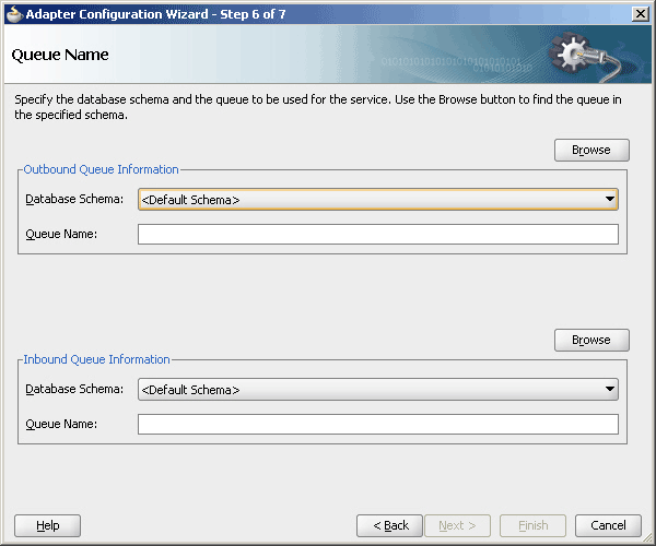
The Adapter Configuration Wizard Queue Name page is displayed, as shown in Figure 7-9.
Figure 7-20 The Adapter Configuration Wizard Queue Name Page
Description of "Figure 7-20 The Adapter Configuration Wizard Queue Name Page"
-
Click Browse to browse for a request queue.
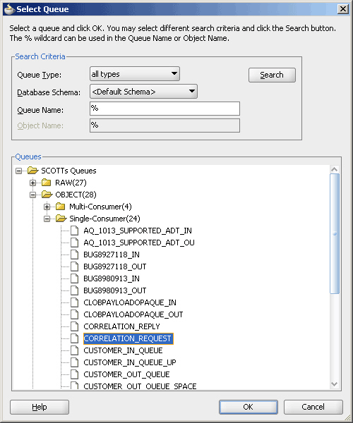
The Select Queue dialog is displayed, as shown in Figure 7-21.
-
Select the required queue, and then click OK.
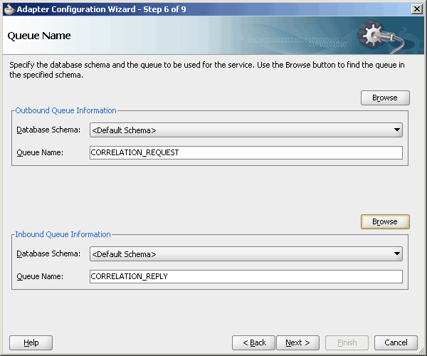
In this example, select CORRELATION_REQUEST. The Queue Name page is displayed with the Queue Name field populated with CORRELATION_REQUEST, as shown in Figure 7-22.
-
Repeat Step 12 and 13 for the enqueue queue information.
The Queue Name page is displayed, as shown in Figure 7-22.
Figure 7-22 The Adapter Configuration Wizard Queue Name Page
Description of "Figure 7-22 The Adapter Configuration Wizard Queue Name Page"
-
Click Next.
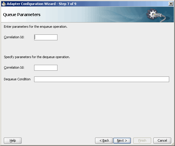
The Adapter Configuration Wizard Queue Parameters page is displayed, as shown in Figure 7-23.
Figure 7-23 The Adapter Configuration Wizard Queue Parameters Page
Description of "Figure 7-23 The Adapter Configuration Wizard Queue Parameters Page"
-
Click Next.
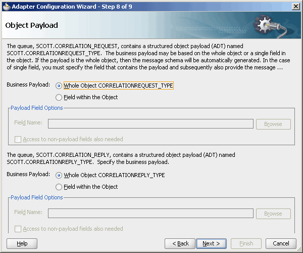
The Adapter Configuration Wizard Object Payload page is displayed, as shown in Figure 7-24.
Figure 7-24 The Adapter Configuration Wizard Object Payload Page
Description of "Figure 7-24 The Adapter Configuration Wizard Object Payload Page"
-
Select the Business Payload options, Whole Object CORRELATIONREQUEST_TYPE and Whole Object CORRELATIONREPLY_TYPE.
-
Click Next.
The Finish screen is displayed. This page shows the path and name of the adapter file that the wizard creates.
-
Click Finish.
You have created an AQ Adapter service for synchronous enqueue/dequeue operations.
-
Click OK.
7.4.1.4.4 Wiring Services and Activities
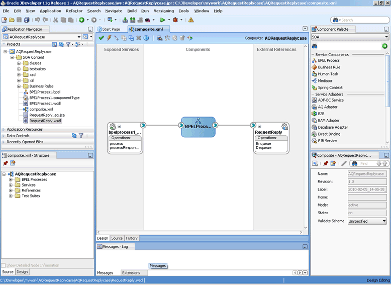
You must assemble or wire the BPEL process and the Outbound adapter reference. Perform the following steps to wire the components:
-
Drag the small triangle in the BPEL process in the Components area to the drop zone that appears as a green triangle in RequestReply in the External References area.
The JDeveloper Composite.xml appears, as shown in Figure 7-25.
Figure 7-25 The JDeveloper - Composite.xml
Description of "Figure 7-25 The JDeveloper - Composite.xml"
-
Click File, Save All.
-
Double-click BPELProcess1. The BPELProcess1.bpel page is displayed.
-
Drag and drop an Invoke activity from the Component Palette to the design area.
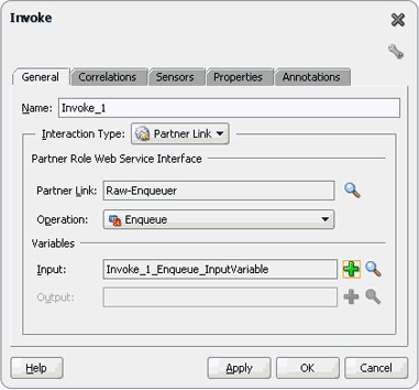
-
Double-click the Invoke activity. The Invoke dialog is displayed.
-
Enter a name for the invoke activity in the Name field.
-
Click Browse Partner Links at the end of the Partner Link field. The Partner Link Chooser dialog is displayed, as shown in Figure 7-26.
Figure 7-26 The Partner Link Chooser Dialog
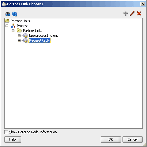
Description of "Figure 7-26 The Partner Link Chooser Dialog"
-
Select RequestReply, and click OK.
-
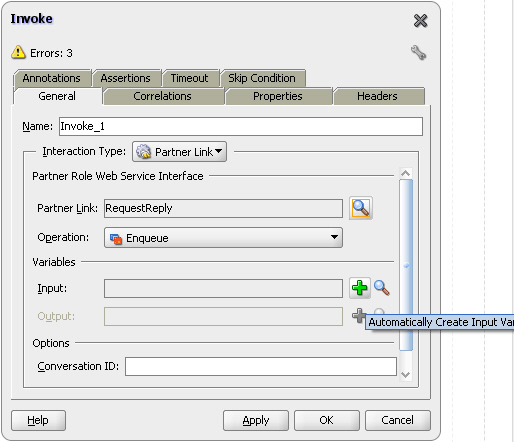
Click the Automatically Create Input Variable icon to the right of the Input variable field in the Invoke dialog, as shown in Figure 7-27. The Create Variable dialog is displayed.
-
Select the default variable name and click OK. The Variable field is populated with the default variable name.
-
Click OK. The JDeveloper BPELProcess1.bpel page appears, as shown in .
Figure 7-28 The JDeveloper - BPELProcess1.bpel Page
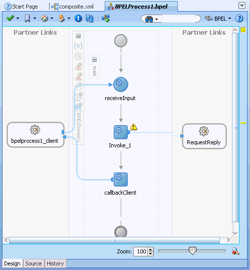
Description of "Figure 7-28 The JDeveloper - BPELProcess1.bpel Page"
-
Drag and drop an Assign activity from the Component Palette to the design area.
-
Double-click the Assign activity. The Assign dialog is displayed.
-
Enter a name for the Assign activity in the Name field.
-
Click the Copy Operation tab.
-
Select Copy Operation. The Create Copy Operation dialog is displayed.
-
Create a copy operation from inputVariable to outputVariable, as shown in Figure 7-29.
Figure 7-29 The Create Copy Operation Dialog
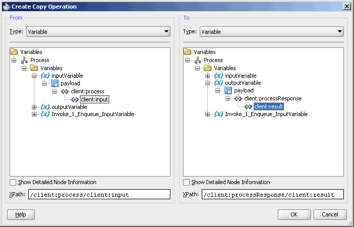
Description of "Figure 7-29 The Create Copy Operation Dialog"
-
Click OK in the Create Copy Operation dialog.
-
Create another copy operation from inputVariable to Invoke_1_Enqueue_InputVariable, as shown in Figure 7-30.
Figure 7-30 The Create Copy Operation Dialog
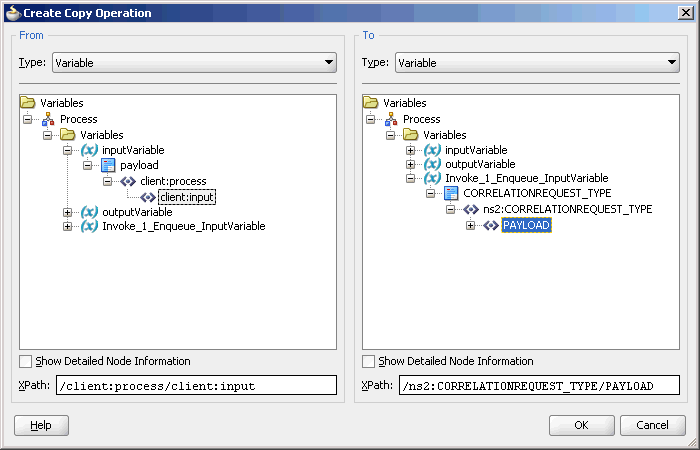
Description of "Figure 7-30 The Create Copy Operation Dialog"
-
Click OK in the Create Copy Operation dialog.
-
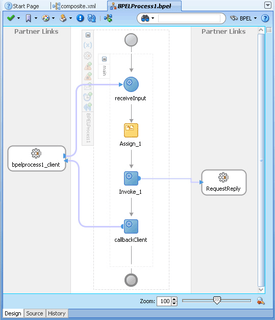
Click OK to return to the JDeveloper BPELProcess1.bpel page, as shown in Figure 7-31.
Figure 7-31 The JDeveloper - BPELProcess1.bpel
Description of "Figure 7-31 The JDeveloper - BPELProcess1.bpel"
-
Click File, Save All.
-
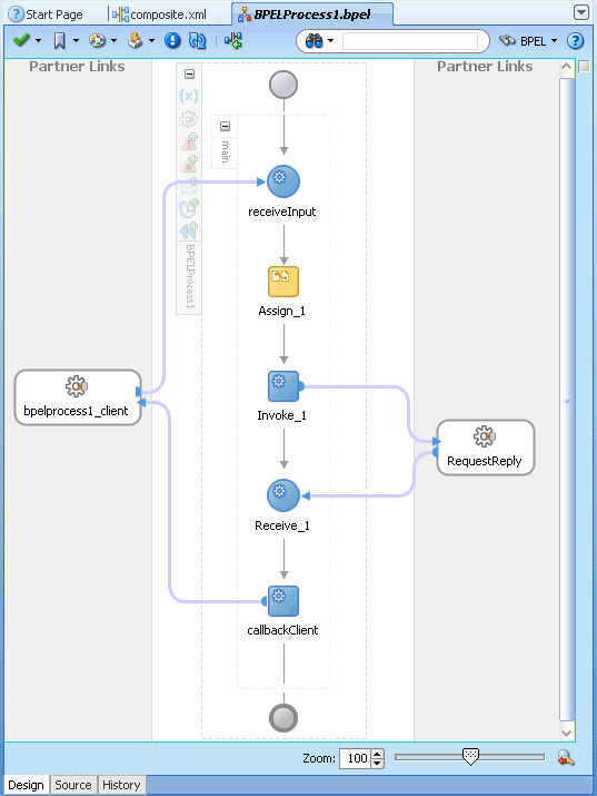
Drag and drop a Receive activity from the Component Palette to the design area.
-
Double-click the Receive activity. The Receive dialog is displayed.
-
Enter a name for the Receive activity in the Name field.
-
Click Browse Partner Links at the end of the Partner Link field. The Partner Link Chooser dialog is displayed.
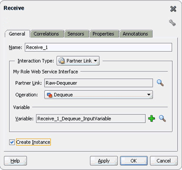
-
Select RequestReply, and click OK.
-
Click the Auto-Create Variable icon to the right of the Variable field in the Receive dialog. The Create Variable dialog is displayed.
-
Select the default variable name and click OK. The Variable field is populated with the default variable name.
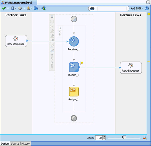
-
Check Create Instance, and click OK. The JDeveloper BPELProcess1.bpel page appears, as shown in .
Figure 7-32 The JDeveloper - BPELProcess1.bpel
Description of "Figure 7-32 The JDeveloper - BPELProcess1.bpel"
7.4.1.4.5 Deploying with JDeveloper
You must deploy the application profile for the SOA project and the application you created in the preceding steps.
The following are the steps to deploy the application profile by using JDeveloper:
-
Create an application server connection by using the procedure described in Chapter 2, "Creating an Application Server Connection for Oracle JCA Adapters."
-
Deploy the application by using the procedure described in Section 2.7, "Deploying Oracle JCA Adapter Applications from JDeveloper."
7.4.1.4.6 Monitoring Using the Fusion Middleware Control Console
You can monitor the deployed composite by using the Fusion Middleware Control Console. Perform the following steps:
-
Navigate to
http://servername:portnumber/em. The composite you deployed is displayed in the Application Navigator. -
Click an instance. The Flow Trace page is displayed.
-
Click the BPEL component instance. The Audit page is displayed.
-
Click the Flow-Debug tab to debug the instance.
7.4.1.4.7 Generated WSDL and JCA Files
The following WSDL file is generated for the Enqueue/Dequeue operation:
<?xml version = '1.0' encoding = 'UTF-8'?>
<?binding.jca Inbound_aq.jca?>
<definitions name="Inbound" targetNamespace="http://xmlns.oracle.com/pcbpel/adapter/aq/Inbound/" xmlns="http://schemas.xmlsoap.org/wsdl/" xmlns:tns="http://xmlns.oracle.com/pcbpel/adapter/aq/Inbound/" xmlns:plt="http://schemas.xmlsoap.org/ws/2003/05/partner-link/" xmlns:obj1="http://xmlns.oracle.com/xdb/SCOTT" xmlns:imp1="http://www.oracle.com/ipdemo/">
    <types>
        <schema attributeFormDefault="qualified" elementFormDefault="qualified" targetNamespace="http://xmlns.oracle.com/pcbpel/adapter/aq/Inbound/" xmlns="http://www.w3.org/2001/XMLSchema" xmlns:tns="http://xmlns.oracle.com/pcbpel/adapter/aq/Inbound/" xmlns:hdr="http://xmlns.oracle.com/pcbpel/adapter/aq/inbound/" xmlns:obj1="http://xmlns.oracle.com/xdb/SCOTT">
            <import namespace="http://xmlns.oracle.com/xdb/SCOTT" schemaLocation="xsd/SCOTT_MAGAZINE_TYPE.xsd"/>
            <import namespace="http://xmlns.oracle.com/pcbpel/adapter/aq/inbound/" schemaLocation="xsd/aqAdapterInboundHeader.xsd"/>
            <complexType name="HeaderCType">
                <sequence>
                    <element name="QueueHeader" type="hdr:HeaderType"/>
                    <element name="PayloadHeader" type="obj1:MAGAZINE_TYPE"/>
                </sequence>
            </complexType>
            <element name="Header" type="tns:HeaderCType"/>
        </schema>
        <schema xmlns="http://www.w3.org/2001/XMLSchema">
            <import namespace="http://www.oracle.com/ipdemo/"          schemaLocation="xsd/simpleMagazine.xsd"/>
        </schema>
<?xml version = '1.0' encoding = 'UTF-8'?>
   <?binding.jca Inbound_aq.jca?>
    <definitions name="Inbound"
    targetNamespace="http://xmlns.oracle.com/pcbpel/adapter/aq/Inbound/
     xmlns="http://schemas.xmlsoap.org/wsdl/"
      xmlns:tns="http://xmlns.oracle.com/pcbpel/adapter/aq/Inbound/"
      xmlns:plt="http://schemas.xmlsoap.org/ws/2003/05/partner-link/"
      xmlns:obj1="http://xmlns.oracle.com/xdb/SCOTT"
     xmlns:imp1="http://www.oracle.com/ipdemo/">
     <types>
 <schema attributeFormDefault="qualified" elementFormDefault="qualified"
    targetNamespace="http://xmlns.oracle.com/pcbpel/adapter/aq/Inbound/"
    xmlns="http://www.w3.org/2001/XMLSchema"
    xmlns:tns="http://xmlns.oracle.com/pcbpel/adapter/aq/Inbound/"
xmlns:hdr="http://xmlns.oracle.com/pcbpel/adapter/aq/inbound/"

xmlns:obj1="http://xmlns.oracle.com/xdb/SCOTT">
<import namespace="http://xmlns.oracle.com/xdb/SCOTT"
schemaLocation="xsd/SCOTT_MAGAZINE_TYPE.xsd"/>
<import namespace="http://xmlns.oracle.com/pcbpel/adapter/aq/inbound/"

     schemaLocation="xsd/aqAdapterInboundHeader.xsd"/>
<complexType name="HeaderCType">
 <sequence>
<element name="QueueHeader" type="hdr:HeaderType"/>
<element name="PayloadHeader" type="obj1:MAGAZINE_TYPE"/>
 </sequence>
</complexType>

   <element name="Header" type="tns:HeaderCType"/>
</schema>

        <schema xmlns="http://www.w3.org/2001/XMLSchema">
       <import namespace="http://www.oracle.com/ipdemo/"
        schemaLocation="xsd/simpleMagazine.xsd"/>
</schema>
</types>
<message name="simpleMagazine_msg">

   <part name="simpleMagazine" element="imp1:simpleMagazine"/>
</message>
     <message name="Header_msg">
     <part name="Header" element="tns:Header"/>
</message>
<portType name="Dequeue_ptt">
    <operation name="Dequeue">
       <input message="tns:simpleMagazine_msg"/>
    </operation>
</portType>
    <plt:partnerLinkType name="Dequeue_plt">
        <plt:role name="Dequeue_role">
            <plt:portType name="tns:Dequeue_ptt"/>
        </plt:role>
   </plt:partnerLinkType>
</definitions>
The following JCA file is generated for the Enqueue/Dequeue operation:
<adapter-config name="RequestReply" adapter="AQ Adapter" wsdlLocation="RequestReply.wsdl" xmlns="http://platform.integration.oracle/blocks/adapter/fw/metadata">

  <connection-factory location="eis/AQ/aqSample" UIConnectionName="aqSample" adapterRef=""/>
  <endpoint-activation portType="Dequeue_ptt" operation="Dequeue" UITransmissionPrimitive="Request-response">
    <activation-spec className="oracle.tip.adapter.aq.inbound.AQDequeueActivationSpec">
      <property name="QueueName" value="CORRELATION_REPLY"/>
    </activation-spec>
  </endpoint-activation>

  <endpoint-interaction portType="Enqueue_ptt" operation="Enqueue" UITransmissionPrimitive="Request-response">
    <interaction-spec className="oracle.tip.adapter.aq.outbound.AQEnqueueInteractionSpec">
      <property name="QueueName" value="CORRELATION_REQUEST"/>
    </interaction-spec>
  </endpoint-interaction>

</adapter-config>
7.4.1.5 Using Correlation ID for Filtering Messages During Dequeue
Perform the following steps to set up an adapter that dequeues messages with a certain correlation ID only.
The adapter dequeues messages enqueued with that same correlation ID only.
For a working example of this use case where an Oracle AQ Adapter dequeues messages enqueued with that same correlation ID, refer to the following samples:
-
adapters-aq-106-messagerejection -
adapters-aq-109-nativecorrelation -
adapters-aq-112-prioritymessageselector -
adapters-aq-113-payloadbasedmessageselector
You can obtain these samples by accessing the Oracle SOA Sample Code site.
7.4.1.6 Enqueuing and Dequeuing from Multisubscriber Queues
Multisubscriber queues are accessible by multiple users, and sometimes, those users are concerned only with certain types of messages within the queue. For example, you may have a multiuser queue for loan applications where loans below $100,000 can be approved by regular loan-approval staff, whereas loans over $100,000 must be approved by a supervisor. In this case, the BPEL process can use one adapter to enqueue loan applications for big loans for supervisors, and another adapter to enqueue loan applications for smaller loans for regular staff in the same multisubscriber queue.
Specify an adapter that enqueues to a multisubscriber queue, and include queue parameters in the Recipients field.
In Step 15, specify Bob in the Recipients field.
The following code is from a JCA file generated by defining an Oracle AQ Adapter that enqueues with a recipient list of Bob:
<adapter-config name="Inbound" adapter="AQ Adapter" xmlns="http://platform.integration.oracle/blocks/adapter/fw/metadata">
    <connection-factory location="eis/AQ/aqSample" UIConnectionName="aqSample" adapterRef=""/>
  <endpoint-interaction portType="Enqueue_ptt" operation="Enqueue">
    <interaction-spec className="oracle.tip.adapter.aq.outbound.AQEnqueueInteractionSpec">
      <property name="QueueName" value="PURCHASEORDER_APPROVAL"/>
      <property name="RecipientList" value="Bob"/>
    </interaction-spec>
  </endpoint-interaction>
</adapter-config>
When dequeuing from a multisubscriber queue, the Queue Parameters window is displayed.
The Consumer field is where you specify the consumer name, or the name of the queue subscriber. This must match the Recipient entry on the enqueue process for the message to be dequeued. When subscribing to a multiconsumer queue, this field is required.
The following code is from a JCA file generated by defining an Oracle AQ Adapter with a consumer name:
<adapter-config name="Dequer_Bob" adapter="AQ Adapter" xmlns="http://platform.integration.oracle/blocks/adapter/fw/metadata">
    <connection-factory location="eis/AQ/manas" UIConnectionName="aqSample" adapterRef=""/>
  <endpoint-activation portType="Dequeue_ptt" operation="Dequeue">
    <activation-spec className="oracle.tip.adapter.aq.inbound.AQDequeueActivationSpec">
      <property name="QueueName" value="PURCHASEORDER_APPROVAL"/>
      <property name="Consumer" value="Bob"/>
      <property name="SchemaValidation" value="false"/>
    </activation-spec>
  </endpoint-activation>
</adapter-config>
For a working example of this use case which demonstrates enqueuing and dequeuing from multisubscriber queues, refer to the following samples:
-
adapters-aq-114-multiconsumeroutbound
You can obtain these samples by accessing the Oracle SOA Sample Code site.
7.4.2 Oracle AQ Adapter ADT Queue
In this sample, the business process receives a message from the AQ Adapter, copies the payload to an outbound message, and invokes the AQ Adapter with the outbound message.The queues involved are ADT queues. In this scenario, where the user has chosen to use whole ADT as the payload, the AQ Adapter Wizard has generated the schema in SCOTT_CUSTOMER_TYPE.xsd, according to the queue structure. During run time, an XML file that matches the schema is created by the adapter for each message.
This section includes the following topics:
-
Section 7.4.2.2, "Creating an Application and an SOA Project"
-
Section 7.4.2.7, "Configuring the Data Sources in the Oracle WebLogic Server Administration Console"
7.4.2.1 Meeting Prerequisites
You must have access to a database with the SCOTT schema.
To perform this use case, you require the following SQL files from the artifacts.zip file contained in the adapters-aq-102-adt sample. These files are located in the artifacts/sql subdirectory of the artifacts.zip fle. Execute the SQL files in the order shown below:
-
setup_user.sql -
create_type_customer.sql -
create_queues.sql -
enqueue_customer.sql -
dequeue_customer.sql
To obtain the adapters-aq-102-adt sample code, access the Oracle SOA Sample Code site
7.4.2.2 Creating an Application and an SOA Project
You must create an JDeveloper application to contain the SOA composite. Use the following steps to create an application and an SOA project:
-
In the Application Navigator of JDeveloper, click New Application.
The Create Generic Application Name your application page is displayed.
-
Enter
ADTin the Application Name field, and click Next.The Create Generic Application Name your project page is displayed.
-
Enter
ADTin the Project Name field. -
In the Available list in the Project Technologies tab, double-click SOA to move it to the Selected list.
-
Click Next.
The Create Generic Application Configure SOA settings page is displayed.
-
Select Composite With Mediator from the Composite Template list, and then click Finish.
You have created a new application and an SOA project.
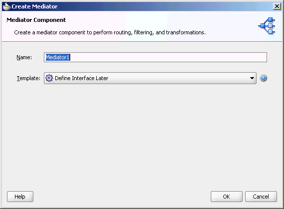
The Create Mediator page is displayed, as shown in Figure 7-33.
-
Enter a name for the Mediator component in the Name field. In this example, retain the default name
Mediator1. -
Select Define Interface Later in the Template list, and then click OK.
You have created a mediator component.
7.4.2.3 Creating an Inbound Oracle AQ Adapter
The following are the steps to create an inbound Oracle AQ Adapter service:
-
In the Component Palette, select SOA.
-
Drag and drop AQ Adapter from the Service Adapters list in the Component Palette to the Exposed Services swim lane in the composite.xml page.
The Adapter Configuration Wizard is displayed.
-
Click Next.
The Service Name page is displayed.
-
Specify a name for the service in the Service Name page. In this example, type
dequeue. -
Click Next.
The Service Connection page is displayed. A database connection is required to configure an Oracle AQ Adapter. You can either create a new connection or select an existing database connection.
-
Click the Create a new database connection icon to create a database connection.
The Create Database Connection page is displayed.
-
Create a database connection, as mentioned in Step 6 of Section 7.4.1.1.3, "Defining an Oracle AQ Adapter Service."
-
Click OK to complete the process of creating a new database connection.
The Service Connection page is displayed, providing a summary of the database connection.
-
Click Next.
The Adapter Interface page is displayed.
-
In the Adapter Interface page, select Define from operation and schema (specified later).
-
Click Next.
The Operation page is displayed.
-
Select Dequeue.
-
Accept the default operation name, and then click Next.
The Queue Name page is displayed.
-
Select a database schema from the list, or click Browse to browse for the schema. In this example, click Browse.
The Select Queue dialog is displayed.
-
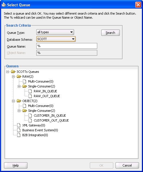
In the Select Queue dialog, perform the following steps:
-
For Queue Type, select all types.
-
For Database Schema, select Scott.
-
Retain the default values for the other fields.
-
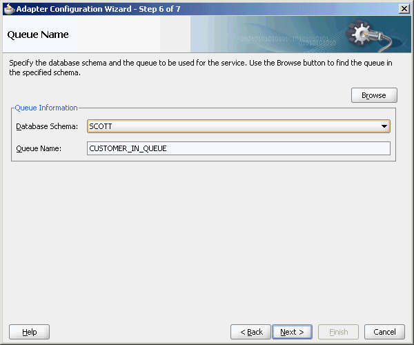
Under Queues, select CUSTOMER_IN_QUEUE.
Figure 7-34 shows the Select Queue dialog.
Figure 7-34 Selecting a Queue for the Inbound Operation
Description of "Figure 7-34 Selecting a Queue for the Inbound Operation"
-
-
Click OK.
The Queue Name dialog with all the fields populated is displayed, as shown in Figure 7-35.
-
Click Next.
The Queue Parameters page is displayed.
-
In the Queue Parameters page, leave the fields empty, and then click Next.
The Object Payload page is displayed.
-
Select a business payload: either the entire object, or just one field within the object.
In this example, select Whole Object CUSTOMER_TYPE.
-
Click Next.
The Finish screen is displayed. This page shows the path and name of the adapter file that the wizard creates.
-
Click Finish.
You have defined an inbound Oracle AQ Adapter
7.4.2.4 Creating an Outbound Oracle AQ Adapter
The following are the steps to create an outbound Oracle AQ Adapter service:
-
In the Component Palette, select SOA.
-
Drag and drop AQ Adapter from the Service Adapters list in the Component Palette to the Exposed Services swim lane in the composite.xml page.
The Adapter Configuration Wizard is displayed.
-
Click Next.
The Service Name page is displayed.
-
In the Service Name field, enter
enqueueand click Next.The Service Connection page is displayed.
-
For Connection, select MyConnection, and then click Next.
The Adapter Interface page is displayed.
-
In the Adapter Interface page, select Define from operation and schema (specified later), and then click Next.
The Operation page is displayed.
-
In the Operation page, select Enqueue, and accept the default operation name.
-
Click Next.
The Queue Name page is displayed.
-
In the Queue Name page, select a database schema from the list, or click Browse to browse for the schema. In this example, click Browse.
The Select Queue dialog is displayed.
-
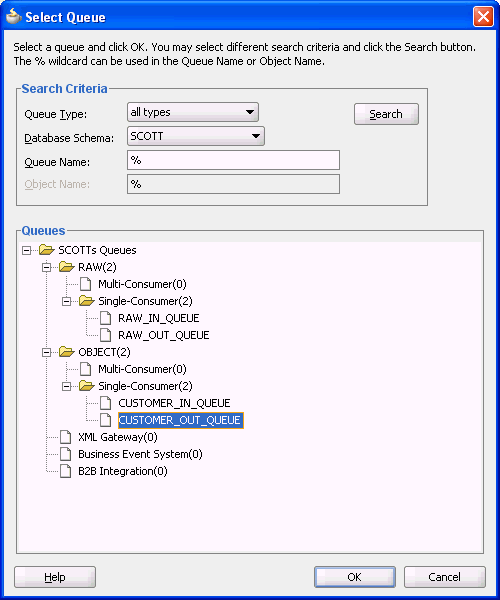
In the Select Queue dialog, perform the following steps:
-
For Queue Type, select all types.
-
For Database Schema, select Scott.
-
Retain the default values for the other fields.
-
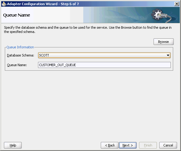
Under Queues, select CUSTOMER_OUT_QUEUE, as shown in Figure 7-36.
Figure 7-36 Selecting a Queue for the Outbound Operation
Description of "Figure 7-36 Selecting a Queue for the Outbound Operation"
-
-
Click OK.
The Queue Name page with all the fields populated is displayed, as shown in Figure 7-37.
-
Click Next.
The Queue Parameters page is displayed.
-
In the Queue Parameters page, leave the fields empty, and then click Next.
The Object Payload page is displayed.
-
Select a business payload, either the entire object, or just one field within the object. In this example, select Whole Object CUSTOMER_TYPE.
-
Click Next.
The Finish screen is displayed. This page shows the path and name of the adapter file that the wizard creates.
-
In the Finish window, click Finish.
You have defined an outbound Oracle AQ Adapter.
7.4.2.5 Wiring Services and Activities
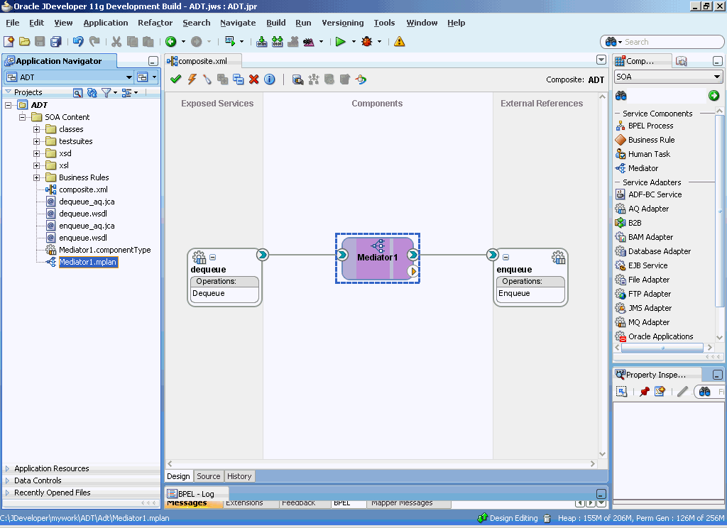
You must assemble or wire the three components that you have created: Inbound adapter service, Mediator component, and Outbound adapter reference. Perform the following steps to wire the components:
-
Drag the small triangle in the Inbound adapter in the Exposed Services area to the drop zone that appears as a green triangle in the Mediator component in the Components area.
-
Drag the small triangle in the Mediator component in the Components area to the drop zone that appears as a green triangle in the Outbound adapter in the External References area.
The JDeveloper composite.xml is displayed, as shown in Figure 7-38.
-
Click File, Save All.
7.4.2.6 Configuring Routing Service
The following are the steps to configure the routing service:
-
Double-click Mediator1.
The Mediator1.mplan window is displayed.
-
Click the Select an existing mapper file or create a new one... icon that is displayed at the end of the Transform Using field.
The Request Transformation Map dialog is displayed, as shown in Figure 7-39.
Figure 7-39 The Request Transformation Map Dialog

Description of "Figure 7-39 The Request Transformation Map Dialog"
-
Select Create New Mapper File, and then click OK.
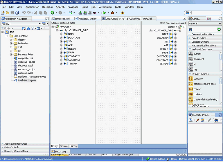
The Transformation window is displayed, as shown in Figure 7-40.
-
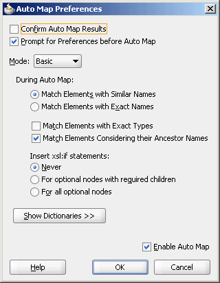
Select the source root elements on the left-hand side of the mapper and drag them over to the destination root elements on the right-hand side to set the map preferences.
The Auto Map Preferences dialog is displayed, as shown in Figure 7-41.
Figure 7-41 The Auto Map Preferences Dialog
Description of "Figure 7-41 The Auto Map Preferences Dialog"
-
Click OK.
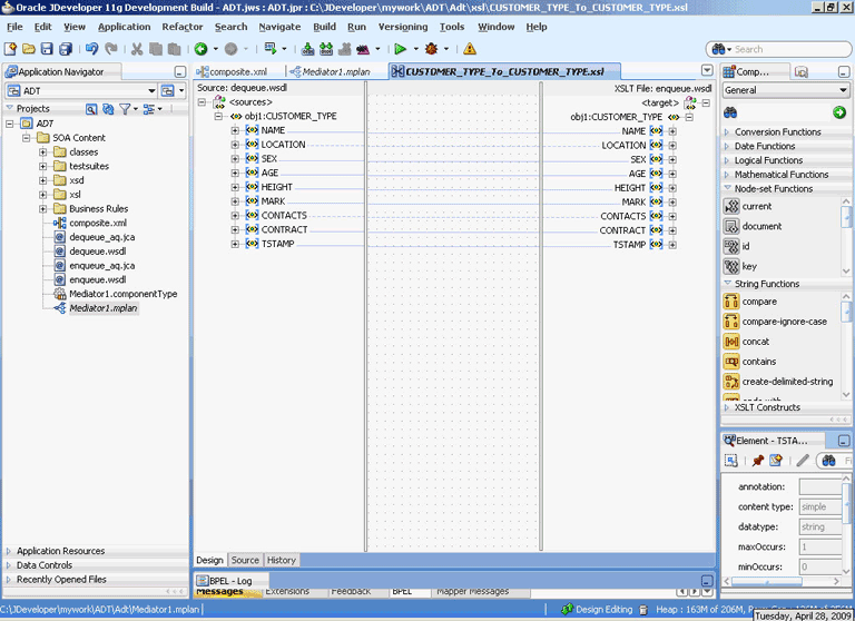
The middle pane of the application window appears as shown in Figure 7-42.
Figure 7-42 The Application Window After Setting the Map Preferences
Description of "Figure 7-42 The Application Window After Setting the Map Preferences"
-
Save and close the tab for the mapper.
-
Save and close the tab for the routing service.
7.4.2.7 Configuring the Data Sources in the Oracle WebLogic Server Administration Console
-
Navigate to
http://servername:portnumber/console. -
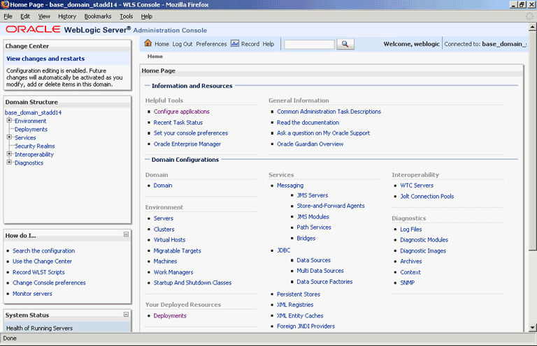
Use the required credentials to open the Home page of the Oracle WebLogic Server Administration Console.
The Home page of the Oracle WebLogic Server Administration Console is displayed, as shown in Figure 7-43.
Figure 7-43 Oracle WebLogic Server Administration Console Home Page
Description of "Figure 7-43 Oracle WebLogic Server Administration Console Home Page"
-
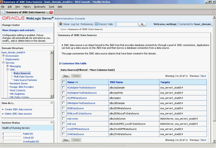
Under Domain Structure, select Services, JBDC, and then click DataSources.
The Summary of JDBC Data Sources page is displayed, as shown Figure 7-44.
Figure 7-44 The Summary of JDBC Data Sources Page
Description of "Figure 7-44 The Summary of JDBC Data Sources Page"
-
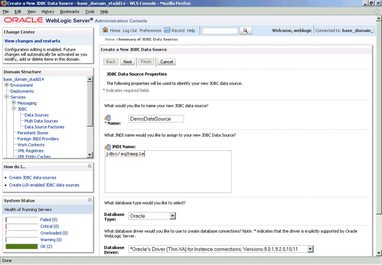
Click New. The Create a New JDBC Data Source page is displayed.
-
Enter the values for the properties to be used to identify your new JDBC data source, as shown in Figure 7-45.
Figure 7-45 The Create a New JDBC Data Source Page
Description of "Figure 7-45 The Create a New JDBC Data Source Page"
-
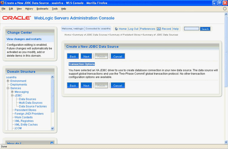
Click Next. The Create a New JDBC Data Source Transaction Options page is displayed, as shown in Figure 7-46.
Figure 7-46 The Create a New JDBC Data Source Transaction Options Page
Description of "Figure 7-46 The Create a New JDBC Data Source Transaction Options Page"
-
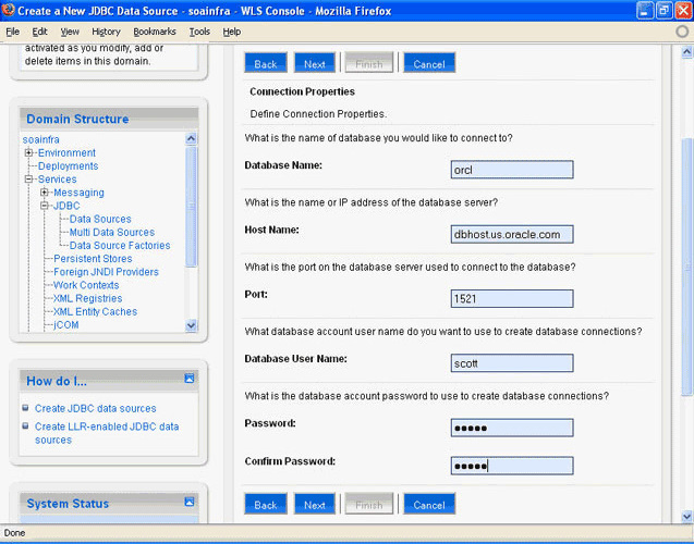
Click Next. The Create a New JDBC Data Source Connection Properties page is displayed, as shown in Figure 7-47.
Figure 7-47 The Create a New JDBC Data Source Connection Properties Page
Description of "Figure 7-47 The Create a New JDBC Data Source Connection Properties Page"
-
Enter the connection properties in the Connection Properties page.
-
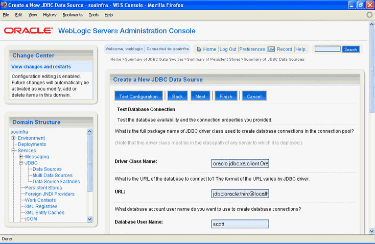
Click Next. The Create a New JDBC Data Source Test Database Connection page is displayed, as shown in Figure 7-48.
Figure 7-48 The Create a New JDBC Data Source Test Database Connection Page
Description of "Figure 7-48 The Create a New JDBC Data Source Test Database Connection Page"
-
Click Test Configuration to test the database availability and the connection properties you provided. A message stating that the connection test succeeded is displayed at the top of the Create a New JDBC Data Source Test Database Connection page.
-
Click Next. The Create a New JDBC Data Source Select Targets page is displayed, as shown in Figure 7-49.
Figure 7-49 The Create a New JDBC Data Source Select Targets Page
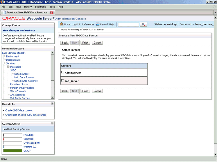
Description of "Figure 7-49 The Create a New JDBC Data Source Select Targets Page"
-
Select a target, and then click Finish.
The Summary of JDBC Data Sources page is displayed, as shown in Figure 7-50. This page summarizes the JDBC data source objects that have been created in this domain. The data source that you created appears in this list.
Figure 7-50 The Summary of JDBC Data Sources Page
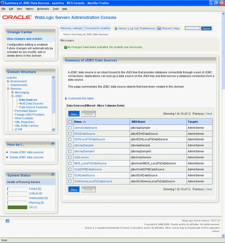
Description of "Figure 7-50 The Summary of JDBC Data Sources Page"
-
Close the Oracle WebLogic Server Administration Console.
7.4.2.8 Deploying with JDeveloper
You must deploy the application profile for the SOA project and the application you created in the preceding steps.
The following are the steps to deploy the application profile by using JDeveloper:
-
Create an application server connection by using the procedure described in Chapter 2, "Creating an Application Server Connection for Oracle JCA Adapters."
-
Deploy the application by using the procedure described in Section 2.7, "Deploying Oracle JCA Adapter Applications from JDeveloper."
7.4.2.9 Monitoring Using the Fusion Middleware Control Console
You can monitor the deployed composite by using the Fusion Middleware Control Console. Perform the following steps:
-
Navigate to
http://servername:portnumber/em. The composite you deployed is displayed in the Application Navigator. -
In the Last 5 Instances pane, there is an entry of a new instance. This new instance is the instance that was triggered when you enqueued a message.
-
Click an instance. The Flow Trace page is displayed.
-
Click the Mediator1 component instance. The Audit page is displayed.
-
Click the Flow-Debug tab to debug the instance.
7.4.3 Oracle AQ Adapter RAW Queue
This use case demonstrates how to use Oracle AQ Adapter to dequeue from and enqueue to an AQ RAW queue.
This section includes the following topics:
-
Section 7.4.3.2, "Creating an Application and an SOA Project"
-
Section 7.4.3.6, "Configuring the Data Sources in the Oracle WebLogic Server Administration Console"
-
Section 7.4.3.8, "Monitoring Using the Fusion Middleware Control Console"
7.4.3.1 Prerequisites
You must have access to a database with the SCOTT schema.
To perform this use case, you require the following SQL files from the artifacts.zip file contained in the adapters-aq-101-raw sample. These files are located in the artifacts/sql subdirectory of the artifacts.zip fle. Execute the SQL files in the order shown below:
-
setup_user.sql -
create_queues.sql -
enqueue_raw.sql -
dequeue_raw.sql -
artifacts/schemas/emp.xsd
To obtain the artifacts.zip contained in the adapters-aq-101-raw sample code, access the Oracle SOA Sample Code site.
To obtain the adapters-aq-101-raw sample code, access the Oracle SOA Sample Code site.
7.4.3.2 Creating an Application and an SOA Project
You must create an JDeveloper application to contain the SOA composite. To create an application and an SOA project, perform the following steps:
-
Open JDeveloper.
-
In the Application Navigator, click New Application.
The Create Generic Application Name your Application page is displayed.
-
Enter
Rawqueuein the Application Name field. -
In the Application Template list, select Generic Application.
-
Click Next.
The Create Generic Application Name your project page is displayed.
-
In the Project Name field, enter a descriptive name, for example,
Raw. -
In the Available list in the Project Technologies tab, double-click SOA to move it to the Selected list.
-
Click Next.
The Create Generic Application Configure SOA settings page is displayed.
-
Select Composite With BPEL from the Composite Template list, and then click Finish.
You have created a new application and an SOA project. This automatically creates an SOA composite.
The Create BPEL Process page is displayed.
-
Enter a name for the BPEL process in the Name field. For example,
BPELRawqueue. -
Select Define Service Later in the Template list, and then click OK.
The
Rawqueueapplication and theRawproject appear in the design area. -
Copy the
emp.xsdfile to theXSDfolder in your project (see Section 7.4.3.1, "Prerequisites" for the location of this file).
7.4.3.3 Creating an Inbound Adapter Service
Perform the following steps to create an inbound Oracle AQ Adapter service that dequeues the message to a queue:
-
In the Component Palette, select SOA.
-
Drag and drop AQ Adapter from the Service Adapters list in the Component Palette to the Exposed Services swim lane in the composite.xml page.
The Adapter Configuration Wizard is displayed.
-
Click Next.
The Service Name page is displayed.
-
In the Service Name field, enter
Raw-Dequeuer, and then click Next.The Service Connection page is displayed.
-
Create a database connection, as mentioned in Step 6 of Section 7.4.1.1.3, "Defining an Oracle AQ Adapter Service."
-
Click Next.
The Adapter Interface page is displayed.
-
In the Adapter Interface page, select Define from operation and schema (specified later), and then click Next.
The Operation page is displayed.
-
In the Operation page, select Dequeue, as shown in Figure 7-51.
-
Accept the default operation name, and click Next.
The Queue Name page is displayed.
Figure 7-51 The Adapter Configuration Wizard Operation Page

Description of "Figure 7-51 The Adapter Configuration Wizard Operation Page"
-
In the Queue Name page, select SCOTT as Database Schema and RAW_IN_QUEUE as Queue Name, as shown in Figure 7-52.
Figure 7-52 The Adapter Configuration Wizard Queue Name Page
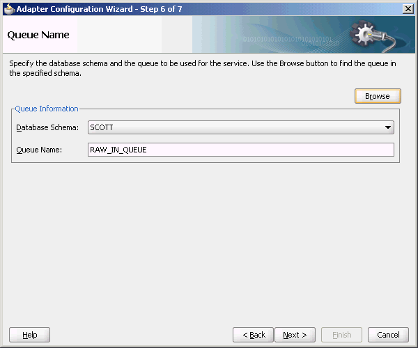
Description of "Figure 7-52 The Adapter Configuration Wizard Queue Name Page"
-
Click Next.
The Queue Parameters page is displayed.
-
Enter the Correlation ID and a Dequeue condition, and then click Next.
The Messages page is displayed.
-
Click Browse at the end of the URL field.
The Type Chooser dialog is displayed.
-
Select Project Schema Files, emp.xsd, and then AQRaw_End2End, as shown in Figure 7-53.
-
Click OK.
The
emp.xsdschema file is displayed in the URL field in the Message dialog, as shown in Figure 7-54.Figure 7-54 The Adapter Configuration Wizard Messages Page
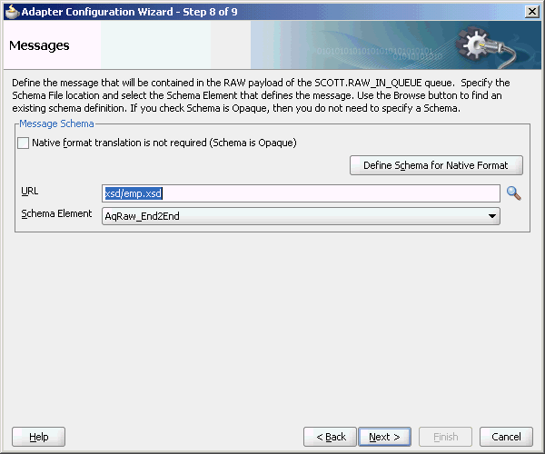
Description of "Figure 7-54 The Adapter Configuration Wizard Messages Page"
-
Click Next. The Finish page is displayed.
-
Click Finish. You have configured the Oracle AQ Adapter service, and the
composite.xmlpage is displayed, as shown in Figure 7-55.Figure 7-55 The JDeveloper Window Composite.xml Page
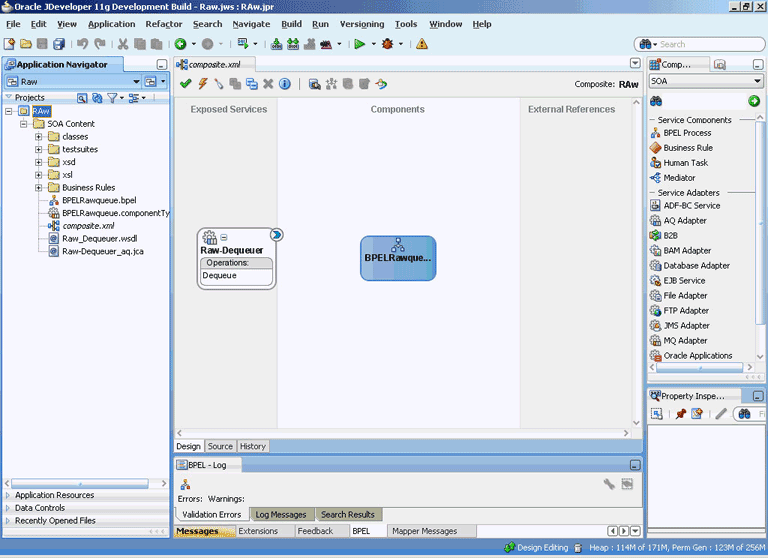
Description of "Figure 7-55 The JDeveloper Window Composite.xml Page"
7.4.3.4 Creating an Outbound Adapter Service
Perform the following steps to create an adapter service that enqueues the request messages and dequeue the corresponding response messages (report) from a queue:
-
Drag and drop AQ Adapter from the Service Adapters list in the Component Palette to the Exposed Services swim lane in the composite.xml page.
The Adapter Configuration Wizard Welcome page is displayed.
-
Click Next. The Service Name page is displayed.
-
Enter
Raw-Enqueuerin the Service Name field, and click OK.The Service Connection page is displayed.
-
Select XA Datasource, and then click Next.
The Operation page is displayed.
-
Select Enqueue.
-
Accept the default operation name, and click Next.
The Queue Name page is displayed.
-
Select SCOTT as Database Schema and RAW_OUT_QUEUE as Queue Name, as shown in Figure 7-56.
Figure 7-56 The Adapter Configuration Wizard Queue Name Page
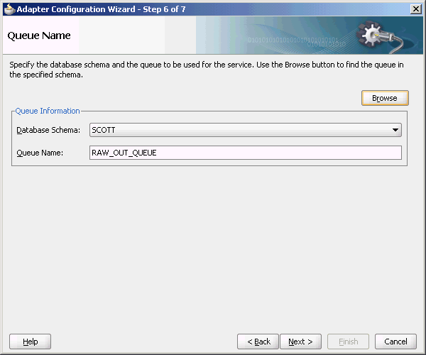
Description of "Figure 7-56 The Adapter Configuration Wizard Queue Name Page"
-
Click Next.
The Queue Parameters page is displayed.
-
Enter the Correlation ID, and then click Next.
The Messages page is displayed.
-
Click Browse for schema file at the end of the URL field.
The Type Chooser dialog is displayed.
-
Select Project Schema Files, emp.xsd, and AQRaw_End2End, as shown in Figure 7-53.
-
Click Next.
The emp.xsd schema file is displayed in the URL field in the Message dialog, as shown in Figure 7-54.
-
Click Next.
The Finish page is displayed.
-
Click Finish.
You have configured the Oracle AQ Adapter service, and the composite.xml page is displayed, as shown in Figure 7-57.
Figure 7-57 The JDeveloper Window Composite.xml Page
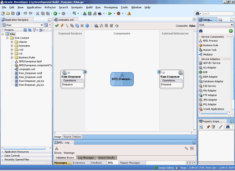
Description of "Figure 7-57 The JDeveloper Window Composite.xml Page"
7.4.3.5 Wiring Services and Activities
You must assemble or wire the three components that you have created: Inbound adapter service, BPEL process, and Outbound adapter reference. Perform the following steps to wire the components:
-
Drag the small triangle in the Raw-Dequeuer in the Exposed Services area to the drop zone that appears as a green triangle in the BPEL process in the Components area.
-
Drag the small triangle in the BPEL process in the Components area to the drop zone that appears as a green triangle in Raw-Enqueuer in the External References area.
Similarly, drag the small triangle in the BPEL process in the Components area to the drop zone in OutboundService in the External References.
The JDeveloper
composite.xmlfile is displayed, as shown in Figure 7-58.Figure 7-58 The JDeveloper- Composite.xml
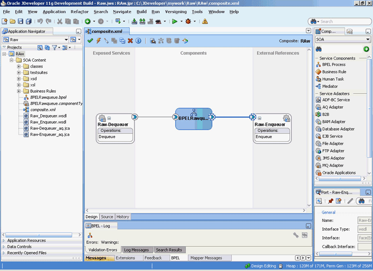
Description of "Figure 7-58 The JDeveloper- Composite.xml"
-
Click File, Save All.
-
Double-click BPELRawqueue.
The BPELRawqueue.bpel page is displayed.
-
Drag and drop the Receive, Assign, and Invoke activities in the order mentioned, from the Component Palette to the Components area.
The JDeveloper
BPELRawqueue.bpelpage is displayed, as shown in Figure 7-59. -
Double-click the Receive activity.
The Receive dialog is displayed.
-
Click the Browse Partner Links icon at the end of the Partner Link field.
The Partner Link Chooser dialog is displayed.
-
Select Raw-Dequeuer, and then click OK.
The Receive dialog is displayed with the Partner Link field populated with the value Raw-Dequeuer.
-
Click the Auto-Create Variable icon that is displayed at the end of the Variable field.
The Create Variable dialog is displayed.
-
Accept the default values, and click OK.
-
Check the Create Instance box, as shown in Figure 7-60, and click OK.
-
Double-click the Invoke activity.
The Invoke dialog is displayed.
-
Click the Browse Partner Links icon at the end of the Partner Link field.
The Partner Link Chooser dialog is displayed.
-
Select Raw-Enqueuer, and then click OK.
The Invoke dialog is displayed with the Partner Link field populated with the value Raw-Enqueuer.
-
Click the Automatically Create Input Variable icon that is displayed at the end of the Input Variable field.
-
Accept the default values, and click OK.
The Invoke dialog is displayed, as shown in Figure 7-61.
-
Click OK.
-
Double-click the Assign activity.
The Assign dialog is displayed.
-
Click the plus icon, and select Copy Operation.
The Create Copy Operation dialog is displayed.
-
Select the variables, as shown in Figure 7-62, and click OK.
Figure 7-62 The Create Copy Operation Dialog
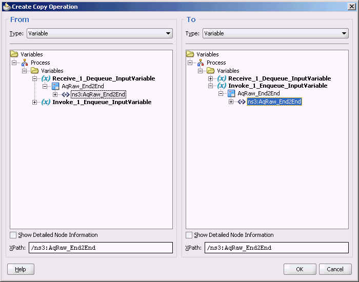
Description of "Figure 7-62 The Create Copy Operation Dialog"
-
Click OK in the Assign dialog.
The JDeveloper
BPELRawqueue.bpelpage is displayed, as shown in Figure 7-63. -
Click File, Save All.
7.4.3.6 Configuring the Data Sources in the Oracle WebLogic Server Administration Console
-
Navigate to
http://servername:portnumber/console. -
Use the required credentials to open the Home page of the Oracle WebLogic Server Administration Console.
-
In the Home page, under Domain Structure, select Services, JBDC, and then click DataSources.
The Summary of JDBC Data Sources page is displayed.
-
Click New. The Create a New JDBC Data Source page is displayed.
-
Enter the values for the properties to be used to identify your new JDBC data source.
-
Click Next. The Create a New JDBC Data Source Transaction Options page is displayed.
-
Click Next. The Create a New JDBC Data Source Connection Properties page is displayed.
-
Enter the connection properties in the Connection Properties page.
-
Click Next. The Create a New JDBC Data Source Test Database Connection page is displayed.
-
Click Test Configuration to test the database availability and the connection properties you provided. A message stating that the connection test succeeded is displayed at the top of the Create a New JDBC Data Source Test Database Connection page.
-
Click Next. The Create a New JDBC Data Source Select Targets page is displayed.
-
Select a target, and then click Finish.
The Summary of JDBC Data Sources page is displayed. This page summarizes the JDBC data source objects that have been created in this domain. The Data Source that you created is displayed in this list.
-
Close the Oracle WebLogic Server Administration Console.
7.4.3.7 Deploying with JDeveloper
You must deploy the application profile for the SOA project and the application you created in the preceding steps.
The following are the steps to deploy the application profile using JDeveloper:
-
Create an application server connection by using the procedure described in Chapter 2, "Creating an Application Server Connection for Oracle JCA Adapters."
-
Deploy the application by using the procedure described in Section 2.7, "Deploying Oracle JCA Adapter Applications from JDeveloper."
7.4.3.8 Monitoring Using the Fusion Middleware Control Console
You can monitor the deployed composite by using the Fusion Middleware Control Console. Perform the following steps:
-
Navigate to
http://servername:portnumber/em.The composite you deployed is displayed in the Application Navigator.
-
In the Last 5 Instances pane, there is an entry of a new instance.
This is the instance that triggered when you enqueued a message.
-
Click an instance.
The Flow Trace page is displayed.
-
Click the BPELRawqueue component instance.
The Audit page is displayed.
-
Click the Flow-Debug tab to debug the instance.
