3 Working with Processes and the Process Editor
This chapter provides information about creating and using business processes in Oracle BPM Studio. It provides a general introduction to business processes and describes the process editor window. It also provides procedural information for creating and using processes, and working with flow objects in processes.
This chapter includes the following sections:
3.1 Getting Started with Processes
Business processes are the core components of process-based business applications created with Oracle BPM Suite.
Projects are higher level wrappers that contain all the resources of a business application, while the processes within the project determine how the application works.
3.1.1 Introduction to Business Processes
A business process is a sequence of tasks which, after they are performed, result in a well-defined outcome.
Business processes are generally created by business analysts who determine the business requirements that must be addressed and define the corresponding process flow using Business Process Composer. They then share the business process with process developers using the process asset manager, the design-time repository provided by Oracle BPM Suite.
The flow is defined by various BPMN flow objects. BPMN (Business Process Modeling Notation) is a graphical notation for capturing business process models. It captures the visual flow and the implementation properties. Oracle BPM Suite uses BPMN 2.0 for modeling and implementing BPMN processes.
3.1.1.1 Types of Processes
Use Oracle BPM to create different types of BPMN processes, depending on what needs to be done. Table 3-1 describes the types of processes supported by Oracle BPM.
Table 3-1 Process Types
| Process Type | Description |
|---|---|
|
Synchronous Service |
Synchronous services are processes that can be invoked from other processes or services synchronously. In a synchronous service, the calling process waits until the process completes before continuing. |
|
Asynchronous Service |
Asynchronous services are processes that can be invoked from other processes or services asynchronously. In an asynchronous service, the calling process does not wait until the process completes before continuing. |
|
Manual Process |
Manual processes are processes that require user interaction. Manual processes begin and end with none start and end events. Immediately after the start event they have an initiator task that triggers the process when a participant submits a UI form. |
|
Reusable Process |
A process that can be invoked from a call activity. Reusable processes can only be invoked using the call activity. Reusable processes also begin and end with none start and end events. In Oracle BPM, a reusable process is identified as having only one none start event; in addition there is no initiator node in the process flow. If the none start event is changed to another type or if an initiator node is added to the process flow, the process is no longer considered to be reusable. For example, if a user task with the initiator pattern or a receive task implemented as a create instance is added immediately after the none start event, the process can no longer be reused or called by another process. |
3.1.2 How to Create a New Business Process
Business processes are created within an Oracle BPM project. You can add one or more processes to your project.
To create a new business process:
The new process is opened in the process editor.
New business processes are created with a start and end event connected by a default sequence flow. The type of start and end events depend on the type of process you created.
3.1.3 How to Open a Business Process
After opening an Oracle BPM project, you can open any of the processes it contains. Processes are opened in the process editor window.
To open a business process:
- Open your project.
- Expand the project node in the Applications window.
- Expand BPMN Processes.
- Double-click the process you want to open.
The process opens in the process editor window. See Introduction to the Process Editor for more information on working with processes in the process editor.
3.1.4 How to Delete a Business Process
You can delete processes from your project. However, you should ensure that there are no remaining references to the deleted process elsewhere in your project.
To delete a business process from a project:
3.1.4.1 What You Need to Know About Deleting a Business Process
When you delete a business process from a project, you must remove any references to it from other parts of your project.
For example, if the deleted process is invoked from another process through a message throw event, reconfigure the invoking process so it no longer refers to the deleted process.
Review the usages of the process you want to delete before deleting it and removing the references.
3.2 Introduction to the Process Editor
The process editor has a canvas on which you can create a model of the process. You can also work with other BPMN processes through conversations.
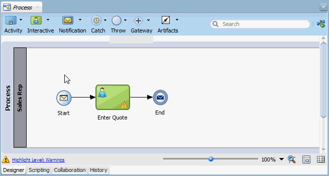
Figure 3-1 shows an example of the process editor.
There are two editor tabs at the bottom of each process editor:
-
Designer editor tab: Provides a canvas and lets you create and model business processes using Business Process Management Notation and Modeling (BPMN). By default, a process opens in Designer mode.
-
Scripting editor tab: Displays the scripts used in the process. You can select the script to display from the list on the top of the editor.
-
Collaboration editor tab: Enables you to work with other BPMN processes and services through conversations.
-
History editor tab: Displays the history of changes. You can also view a list of changes and compare different versions of the process.
The term 'process editor' refers to the Designer mode of the editor, unless explicitly specified otherwise.
When a process is opened in the process editor window, a flow object toolbar at the top of the canvas enables you to insert various BPM notations. The status bar below the canvas provides controls that enable you to show and fix errors or warnings, configure the layout, and change the zoom level. The process editor is also synchronized with a view of the process in the Thumbnail window. For more information about thumbnails, see Thumbnail View.
Flow Object Toolbar and Drop-down Menus
The flow object toolbar provides easy access to common BPM flow objects. The flow objects are available through the following drop-down menus on the toolbar:
-
Activity: Includes activities such as Call, Business Rule, and Send.
-
Interactive: Includes interactive activities such as User and Initiator.
-
Notification: Includes activities such as Mail and Voice.
-
Catch: Includes events such as Error and Message.
-
Throw: Includes events such as Throw Signal and End Signal.
-
Gateway: Includes Exclusive and Parallel.
-
Artifacts: Includes Measurement and Sequence Flow.
The drop-down menus provide the same flow objects as found in the Component Palette. For more information on BPMN flow objects, see “BPMN Flow Object Reference" in the Developing Business Processes with Oracle Business Process Composer.
Search
Enables you do run a search for a specific flow object using its name.
Go To Composite Editor
This toolbar item opens the SOA Composite Editor.
Highlight Level
This status bar item enables you to change the severity level of messages to be highlighted in the process by special overlay symbols. For information on how to use this item, see How to Change the Highlight Level for Messages in a Process.
Zoom
This status bar item enables you to change the scale of the process. For information on how to use the zoom tool, see How to Change the Zoom Level in a Process.
Layout and Show Grid
These status bar items enable you to use and configure the automatic layout utility, and turn on or turn off a grid overlay in the process. For more information, see How to Configure Layout Properties and Use a Grid in a Process.
3.3 Working with Processes
As you work with processes in the process editor, you can open more than one process, export a process as an image, change the highlight level for messages, change the zoom level, or configure layout properties.
You can open one or more processes in the editor window. Each process is identified by a process name in a document tab at the top of the editor window. Only one process can be in focus (active) at any time.
3.3.1 How to Export a Process As an Image
You can export an entire process design to a PNG file only.
To export a process:
- Open the process you want to export as an image.
- Right-click anywhere on the canvas where there is no flow object and choose Generate Process Image.
- In the Select Object File dialog box, navigate to the directory of your choice.
- Enter a file name and click OK.
3.3.2 How to Change the Highlight Level for Messages in a Process
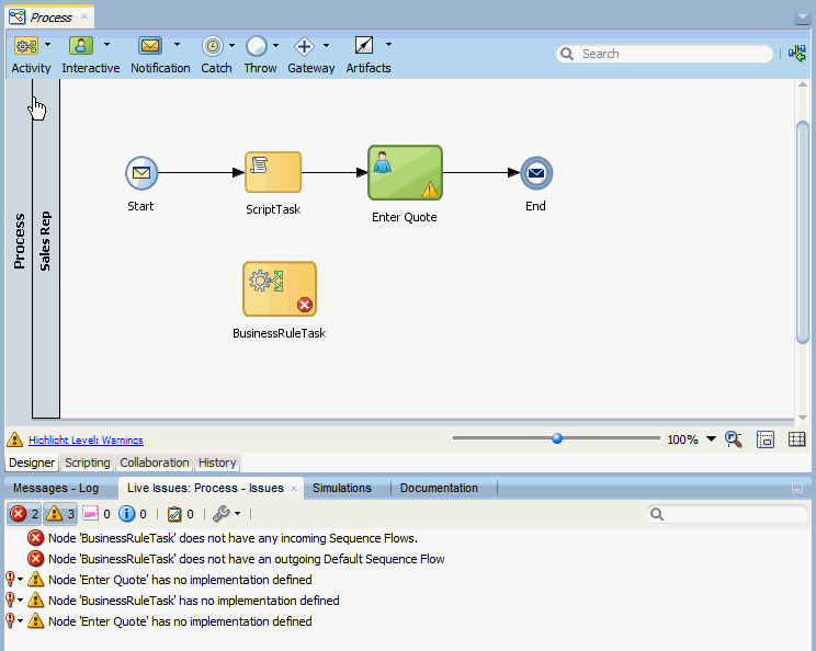
When a flow object in a process has an error or a warning message, the flow object icon in the process editor is highlighted by a red error symbol or a yellow warning symbol overlay.
You can change the severity level of messages to be highlighted in the process. The highlight levels available are:
-
None: No errors or warnings are displayed.
-
Errors: Only errors are displayed.
-
Warnings: Both warnings and errors are displayed.
Note:
The highlight level you set in the process editor affects flow objects in the active process only. Other processes already opened in other process editor tabs are not affected. However the highlight level set in the active process editor does affect all new processes that you subsequently open or create in the same project. This is because the Highlighting Level preference in the Project Preferences dialog box is updated to the same value at the time you make the process-level highlight change.
To set the severity level of messages to be highlighted for all processes in a project, see How to Edit Project Preferences.
To change the highlight level for messages to show in a process:
Note:
To display messages associated with a flow object in the process, see How to Display and Fix Errors or Warnings in Flow Objects.
3.3.3 How to Change the Zoom Level in a Process
Three status bar items are provided in the process editor to enable you to change the scale of the active process quickly.
To change the zoom level in a process:
3.3.4 How to Configure Layout Properties and Use a Grid in a Process
[This is not consistent with the highlight level behavior, where the action affects the active process only. Here, changing the layout/grid in one process immediately affects the setting in all other opened processes in the editor window, except the run once utility which affects the active process only. Dev said this inconsistent behavior will be revisited later.]
You can configure a process to use the automatic layout utility: When automatic layout is turned on, JDeveloper automatically aligns the placement of flow objects horizontally and vertically as they are added to the process. When automatic layout is off, you can use a grid of horizontal and vertical lines in the process background to help you align flow objects.
You can also activate lanes optimization in the process, which means JDeveloper would remove unnecessary lanes by moving all activities to other named lanes, where possible.
To use the automatic layout utility and optimize lanes in a process:
-
Open the process in the process editor.
-
On the status bar click Layout.
-
In the pop-up dialog, click OFF to turn on the automatic layout utility or click ON to turn it off.
-
When automatic layout is on, select Optimize lanes to prune interactive roles with non-interactive activities.
Lane optimization is available only when the automatic layout utility is turned on.
-
When automatic layout is off, click Run layout once to automatically align flow objects in the process without turning the automatic layout utility on in the process and project.
To use a grid in the process:
- Open the process in the process editor.
- On the status bar, select Show Grid to add a grid on the process design.
- To turn off the grid, deselect Show Grid.
Note:
With the exception of the Run layout once utility, when you activate or deactivate lanes optimization, automatic layout or the grid in a process, similar configuration settings in the Project Preferences dialog box are simultaneously updated to the same values. This means all processes in the project will use the same settings until you change any preference in the dialog box or in the process editor status bar.
To set the layout or grid preferences in a project, see How to Edit Project Preferences.
3.4 Working with Flow Objects in Your Process
You can use several different methods to add flow objects to the process. You can also edit the properties, copy and paste, and mark flow objects as draft. You can also use sequence flows and fix errors or warnings.
For more information on BPMN flow objects, see "BPMN Flow Object Reference" in the Developing Business Processes with Oracle Business Process Composer.
3.4.1 How to Add Flow Objects from the Component Window
You can add BPMN flow objects from the Component window.
To add flow objects from the Component window:
3.4.2 How to Add Flow Objects from the Process Editor Toolbar
The process editor toolbar contains drop-down menus for the same BPMN flow objects as found in the Component Palette. This is useful when you maximize the process editor window to full screen mode and you cannot use the Component Palette to add flow objects.
To add flow objects from the process editor toolbar:
Note:
The last object you chose from a drop-down menu becomes the default selected object for that menu. The default object is indicated by the menu icon on the toolbar. This means the next time you click that menu icon and then click the canvas, the default object is added to the process.
3.4.3 How to Add Flow Objects from a Context Menu
You can add BPMN flow objects using a context menu on the process editor canvas.
To add flow objects from a context menu:
3.4.4 How to Edit Flow Object Properties
You can use the Properties dialog box to edit the properties for each flow object within your process.
To edit the properties of a flow object:
- Open the process containing the flow object you want to edit.
- Right-click the flow object, then select Properties.
- Edit the properties as necessary, then click OK.
3.4.5 How to Display and Fix Errors or Warnings in Flow Objects
When a process or a flow object in the process has an error or a warning, the process icon in the Applications window or the flow object icon in the process editor has a red error 'x' circle symbol or a yellow warning '!' (exclamation mark) triangle symbol.
In the process editor, you can use the message area above the status bar to display error and warning messages related to a flow object or you can display a list of all the errors or warnings in the process. Then you can select a problem for fixing, if a fix suggestion is available.
To display and fix errors or warnings in flow objects:
Note:
To display all errors and warnings for all the flow objects that have problems, deselect the selected object in the process editor with the message area already expanded. If the message area is hidden, click Show without selecting any object in the process.
3.4.6 How to Mark and Unmark a Flow Object as Draft
A flow object marked as Draft means the object has a default implementation where data object values can be set. A Draft flow object is indicated in a process by a gray icon in place of its default color icon.
Flow objects marked as Draft are considered to be unimplemented. However a process that contains Draft flow objects can still be deployed, but a warning will be issued.
Only events and activities can be marked as Draft. Events and activities that already have implementations defined can also be marked as Draft. Existing data associations, however, will be removed in the implementation when you change the Draft status.
Data objects in a Draft flow object can be initialized using custom assignments in the Data Associations dialog box, but implementation arguments are not available in the dialog box. An error message appears at the top of the Data Associations dialog box when you attempt to define data associations in a Draft flow object, as shown in Figure 3-4.
For more information about data objects and data associations, see Chapter 8, "Handling Information in Your Process Design".
To mark and unmark a flow object as draft:
Note:
You can also toggle the Draft state of a flow object through the Is Draft check box in the Properties dialog box of the flow object. For information about how to use the Properties dialog box, see How to Edit Flow Object Properties.
3.4.7 How to Copy and Paste Flow Objects
You can copy and paste one or more flow objects within a process or between processes. Note that sequence flows, boundaries and measurements are copied only if the following conditions are met:
-
the transitions, boundaries and measurements are selected
-
all the elements the transitions, boundaries and measurements are attached to are also selected for copy
Note:
You cannot copy and paste objects inside an event subprocess.
To copy and paste a flow object in a process:
If necessary, use the Run layout once utility in the Layout popup to align the objects automatically. For more information about automatic layout in the process editor, see How to Configure Layout Properties and Use a Grid in a Process.
3.4.8 How to Add and Use Sequence Flows
A new business process is created with a start and end event already connected by a sequence flow. As you add flow objects to the process, inserting them anywhere along the sequence flow, JDeveloper automatically connects the new objects into the flow.
You can, however, create your own sequence flows where they are applicable and needed. For example, you may need to add a gateway with two conditional sequence flows and one default sequence flow.
For more information about controlling process flow with sequence flows and gateways, see "BPMN Flow Object Reference" in the Developing Business Processes with Oracle Business Process Composer.
You can also change the style of the arrow line used in a sequence flow and move a connected object from one sequence flow to another.
To connect two objects with a sequence flow:
-
Open the process.
-
In the Components window, expand Artifacts and then click Sequence Flow.
-
In the process editor, place the cursor over the first object where the outgoing sequence flow starts.
The cursor changes to a + plus symbol when it is over an object where an outgoing sequence flow can start. For example, you can start an outgoing flow from a gateway object but not from a start event that already has an outgoing flow.
-
Click to anchor the start of the sequence flow, then drag the cursor to the second object where the sequence flow should end.
As you drag the cursor, a line with an arrow at the end is drawn on the canvas. When the cursor is over an object where an incoming sequence flow can be placed, you should see a + plus symbol.
-
Click to anchor the end of the sequence flow.
By default the two objects are connected by an orthogonal style sequence flow.
To change the style of a sequence flow:
-
Open the process.
-
Right-click the sequence flow line that you wish to modify.
-
From the context menu, choose Style and then choose Straight, Curved or Orthogonal.
The existing style of the selected line is grayed out in the context submenu.
To move a connected object from one sequence flow to another:
3.5 Working with Draft Processes
A draft process is a process that has one or more flow objects which do not have their implementation defined. With draft projects, you can test the parts of the process that have been completed before all flow objects have been implemented.
You create draft processes by marking one or more flow objects within the process as draft.
3.5.1 Introduction to Draft Processes
When you configure a flow object to be a draft, you cannot configure data associations for the flow object. If mark a flow object as draft that you have previously assigned data associations for, the data associations will be lost.
You can define the implementation details of a draft flow object. However, it is not required. A draft flow object with no implementation defined will not generate errors when the project is validated.
3.6 Documenting Your Process
With the documentation editor, you can add process or use case documentation for the process and the flow objects.
The documentation editor contains a toolbar and editor pane where you enter the documentation.
3.6.1 Introduction to the Documentation Editor
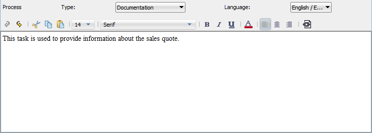
Figure 3-5 shows the documentation editor.
The toolbar allows you to select the type of documentation and the language, if you have defined additional languages for the product.
For more information on the documentation editor toolbar see the online Help.
3.6.2 How to Add Documentation to Your Process
Use the Documentation editor to add one of these types of documentation to your process.
-
Documentation: This is the documentation the process participants see using the Process Workspace application.
-
Use case documentation: This is the documentation that process analysts and process developers see when updating a business process.
To add documentation to a flow element in a process
- Open the process where you want to add documentation.
- From the Window menu select Documentation.
- Select the flow object within your process that you want to document.
- From the drop-down list, select the type of documentation you want to add.
- Enter your documentation.
- From the File menu select Save to save your changes.
3.6.3 Generating Process Reports for Your Project
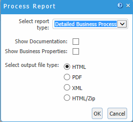
You can generate reports that list each process in your project and show detailed information about each process.
-
Detailed Business Process
-
Business Requirements
-
Issues and Comments
-
Data Objects
-
Process vs Data
-
Data vs Process
-
Human Tasks vs Process
-
Service vs Process
-
User Tasks
-
Process image
-
RACI (responsible, accountable, consulted, and informed)
To generate a process report:
For more information about these reports, see Documenting Your Process.


