16 Working with Pipelines in Oracle JDeveloper
This chapter describes how to create and configure pipelines, or message flows, using Oracle JDeveloper. Sections include adding and configuring pipeline pairs, conditional branches, stages, operational branches, route nodes, and error handlers.
For more detailed information on message flows, see Modeling Message Flow in Oracle Service Bus.
This chapter includes the following sections:
16.1 Adding a Pipeline Component in JDeveloper
Add a pipeline to define the message flow and any data transformation or validation for the project. You can also define errors and reporting in a pipeline. When you create a new pipeline, you have the option to generate a proxy service from the pipeline configuration.
16.2 Viewing and Editing Pipelines in JDeveloper
The message flow corresponding to a proxy service is handled by a pipeline. This section describes how to view and pipelines using the Pipeline Editor.
16.3 Adding Shared Variables to Pipelines in JDeveloper
If two pipelines in a single call chain declare the same shared variable, then they read and modify the same variable. In other words, if pipeline P1 declares a shared variable var, and pipeline P2 also declares a shared variable var, then any changes to var in P1 are visible in P2, and vice versa. A shared variable must be of the String, Boolean, or XML data type.
When a proxy service receives and processes a message, all invoked pipelines that use a shared variable, read and write the same value for the variable. A subsequent message received by the proxy creates a new instance of the shared variable in the invoked pipelines.
Shared variables work across local proxy invocations and split-join component invocations. For example, say pipelines P1 and P2 declare a shared variable. Now, if P1 invokes a local proxy service or split-join component, which in turn invokes P2, then P1 and P2 continue to share the shared variable.
The following restrictions apply to using shared variables:
-
System variables (such as
$body, $attachments, $operation, $inbound, $outbound) cannot be shared. -
Variables cannot be shared across non-local proxy invocations. For example, say a pipeline invokes an HTTP proxy service, the shared variable is not propagated across this call.
-
Variables cannot be shared between pipeline and split-join resources.
-
Variables with Java and binary content types are not supported. For example, an XML-typed variable that has
<ctx:java-content/>in its XML structure, is not supported as a shared variable.
16.3.1 How to Add a Shared Variable to a Pipeline in JDeveloper
Use the Pipeline Editor to add a shared variable to the message flow for the pipeline.
To add a shared variable to a pipeline
- In the Pipeline Editor, right-click the start node.
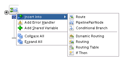
- Select Add Shared Variable from the context menu that appears.
- Enter a name for the shared variable in the Enter Shared Variable Name field.
- Click OK to add the shared variable to the pipeline.
16.4 Adding Pipeline Pair Nodes to Pipelines in JDeveloper
Pipelines can include zero or more pipeline pair nodes: request and response pipelines for the proxy service (or for the operations on the service), and error handler pipelines that can be defined for stages, pipelines, and proxy services. Pipelines can include one or more stages, which in turn include actions.
16.4.1 How to Add a Pipeline Pair Node to a Pipeline in JDeveloper
Use the Pipeline Editor to add a pipeline pair to the message flow for the pipeline.
To add a pipeline pair to a pipeline:
-
In the Pipeline Editor, right-click the start node icon.
-
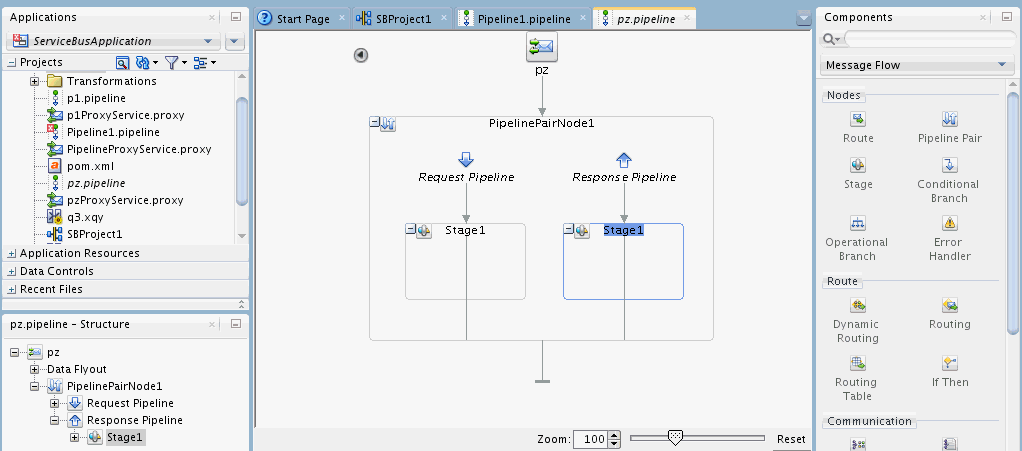
Select Insert Into > PipelinePairNode from the context menu that appears. The pipeline pair node is inserted.
Note:
You can alternatively choose to drag a Pipeline Pair component from the Components window to the appropriate location in the Pipeline Editor. The Pipeline Pair component can be found under the Nodes section of the Message Flow category.
-
To change the default name and add a description for the pipeline pair node, do the following:
-
Click the Pipeline Pair Node to select it. The Properties window displays the properties for the selected component.
Note:
If the Properties window is not visible, select Properties from the Window main menu.
-
In the Properties window, change the name and description, as desired.
-
Click Save in the Oracle JDeveloper toolbar.
-
-
To add stages to the pipeline, see Adding Stages to Pipelines in JDeveloper.
-
To add actions to stages in the pipeline. See Adding and Editing Actions in Pipelines in JDeveloper.
-
On the Pipeline Editor, continue to construct the pipeline, as described in Viewing and Editing Pipelines in JDeveloper.
-
Click Save in the Oracle JDeveloper toolbar.
16.5 Adding Conditional Branches to Pipelines in JDeveloper
A branch node allows processing to proceed along exactly one of several possible paths. Branching is driven by an XPath-based switch table. Each branch in the table specifies a condition (for example, <500) that is evaluated in order down the pipeline against a single XPath expression (for example, ./ns: PurchaseOrder/ns:totalCost on $body). Whichever condition is satisfied first determines which branch is followed. If no branch condition is satisfied, then the default branch is followed. A branch node may have several descendants in the pipeline: one for each branch, including the default branch.
If the proxy service is not based on a WSDL file and receives multiple document types as input, you can consider using a conditional branch node.
Conditional branching is driven by a lookup table with each branch tagged with a simple, but unique, string value. A variable in the message context is designated as the lookup variable for that node, and at runtime, its value is used to determine which branch to follow. If no branch matches the value of the lookup variable, the default branch is followed. You should design the proxy service in such a way that the value of the lookup variable is set before reaching the branch node.
16.5.1 How to Add a Conditional Branch to a Pipeline in JDeveloper
Use the Pipeline Editor to add a conditional branch to the message flow for the pipeline.
To add a conditional branch to a pipeline:
-
In the Pipeline Editor, right-click the start node icon) or a Branch Node icon.
-
Select Insert Into > Conditional Branch from the context menu that appears.The conditional branch node is added, and any existing nodes after the inserted branch node are moved to the default branch of the new conditional branch node.
Note:
You can alternatively choose to drag a Conditional Branch component from the Components window to the appropriate location in the Pipeline Editor. The Conditional Branch component can be found under the Nodes section of the Message Flow category.
-
To change the properties for the conditional branch node, do the following:
-
Click the Conditional Branch node to select it. The Properties window displays the properties for the selected component.
Note:
If the Properties window is not visible, select Properties from the Window main menu.
-
Under the General section, change the name and description, as desired.
-
Under the Condition section, specify an XPath expression to use as the condition. You can invoke the XPath Expression Builder by clicking the fx icon.
-
Click Save in the Oracle JDeveloper toolbar.
-
-
To change the properties for a branch, do the following:
-
Click the branch node to select it. The Properties window displays the properties for the selected component.
Note:
If the Properties window is not visible, select Properties from the Window main menu.
-
Under Name, specify a name for the branch.
-
Under Value, specify an operator and an XPath expression to use as the value. You can invoke the XPath Expression Builder by clicking the fx icon.
-
Click Save in the Oracle JDeveloper toolbar.
-
-
Optionally:
-
Click the Add New Branch icon to add a new branch node.
-
Right-click a branch, and select Delete to delete the branch.
-
-
Click Save in the Oracle JDeveloper toolbar.
-
On the Pipeline Editor, continue to construct the pipeline, as described in Viewing and Editing Pipelines in JDeveloper.
-
Click Save in the Oracle JDeveloper toolbar.
16.6 Adding Operational Branches to Pipelines in JDeveloper
When pipelines define Web Services Description Language (WSDL)-based proxy services, operation-specific processing is required. Instead of configuring a branching node based on operations manually, Service Bus provides a minimal configuration branching node that automatically branches based on operations. In other words, when you create an operational branch node in a pipeline, you can quickly build your branching logic based on the operations defined in the WSDL file because the Oracle Service Bus Console presents those operations in the branch node configuration page.
A branch node allows processing to proceed along exactly one of several possible paths. Branching is driven by an XPath-based switch table. Each branch in the table specifies a condition (for example, <500) that is evaluated in order down the pipeline against a single XPath expression (for example, ./ns: PurchaseOrder/ns:totalCost on $body). Whichever condition is satisfied first determines which branch is followed. If no branch condition is satisfied, then the default branch is followed. A branch node may have several descendants in the pipeline: one for each branch, including the default branch.
16.6.1 How to Add an Operational Branch to a Pipeline in JDeveloper
Use the Pipeline Editor to add an operational branch to the message flow for the pipeline.
To add an operational branch to a pipeline:
-
In the Pipeline Editor, right-click the start node or a Branch Node icon.
-
Select Insert Into > Operational Branch from the context menu that appears. The operational branch node is added, and any existing nodes after the inserted branch node are moved to the default branch of the new operational branch node.
Note:
You can alternatively choose to drag an Operational Branch component from the Components window to the appropriate location in the Pipeline Editor. The Operational Branch component can be found under the Nodes section of the Message Flow category.
-
To change the properties for the operational branch node, do the following:
-
Click the operational branch node to select it. The Properties window displays the properties for the selected component.
Note:
If the Properties window is not visible, select Properties from the Window main menu.
-
Change the name and description, as desired.
-
Click Save in the Oracle JDeveloper toolbar.
-
-
To change the properties for a branch, do the following:
-
Click the branch node to select it. The Properties window displays the properties for the selected component.
Note:
If the Properties window is not visible, select Properties from the Window main menu.
-
Select the Operation represented by the branch.
-
Click Save in the Oracle JDeveloper toolbar.
-
-
Optionally:
-
Click the Add New Branch icon to add a new branch node.
-
Right-click a branch, and select Delete to delete the branch.
-
-
On the Pipeline Editor, continue to construct the pipeline, as described in Viewing and Editing Pipelines in JDeveloper.
-
Click Save in the Oracle JDeveloper toolbar.
16.7 Adding REST Branches to Pipelines in JDeveloper
When pipelines define native, untyped (no WADL at design time), REST-based proxy services, client request-specific processing is required. Instead of configuring a branching node based on these requests manually, Service Bus provides a minimal configuration branching node that automatically branches based on media type consumed, relative URI, HTTP Verb, or a combination of these criteria. When you create a REST branch node in a pipeline, you can quickly build your branching logic based on these criteria.
-
Consumes Media Types: a list of media types sent by a client that are allowed for this branch, such as
application/json. -
Path: a single URI pattern (relative URI path) allowed for this branch. For example,
/dogs/{id}is a valid path. -
Verb: a single HTTP Verb (GET, PUT, POST, or DELETE) allowed for this branch.
Note:
If the REST branch label contains a parameterized path expression, such as /name/{PlaceName}/zip/{ZipCode}, as part of the execution of REST branch, message context variables PlaceName and ZipCode are automatically defined with the values of the actual path segments at runtime, for example, Pittsburgh and 15217. The values of these parameters are extracted from inbound HTTP relative path metadata.
The scope of the variables is all of the actions nested in the corresponding branch
REST Branches can be used only in pipelines for native, untyped REST services; other service types are not supported.
16.8 Adding Stages to Pipelines in JDeveloper
Request pipelines, response pipelines, and error handlers can contain stages, where you configure actions to manipulate messages passing through the pipeline.
16.8.1 How to Add a Stage to a Pipeline in JDeveloper
Use the Pipeline Editor to add a stage to the message flow for the pipeline.
To add a stage to a pipeline:
-
In the Pipeline Editor, right-click a Request Pipeline icon or Response Pipeline icon in a pipeline pair node.
-
Select Insert Into > Stage from the context menu that appears. A stage node is added.
Note:
You can alternatively choose to drag a Stage component from the Components window to the appropriate location in the Pipeline Editor. The Stage component can be found under the Nodes section of the Message Flow category.
-
To change the default name and add a description for the stage, do the following:
-
Click the stage node to select it. The Properties window displays the properties for the selected component.
Note:
If the Properties window is not visible, select Properties from the Window main menu.
-
Edit the Name and Description fields for the selected stage node.
-
Click Save in the Oracle JDeveloper toolbar.
-
-
To add actions to the stage, right-click the Stage icon, then click Insert Into > ActionName from the context menu that appears. See Adding and Editing Actions in Pipelines in JDeveloper.
-
To add error handling to the stage, right-click the Stage icon, then click Add Stage Error Handler from the context menu that appears. See Adding Error Handlers in JDeveloper.
-
Continue to construct the pipeline, as described in Viewing and Editing Pipelines in JDeveloper.
-
Click Save in the Oracle JDeveloper toolbar.
16.9 Adding Route Nodes to Pipelines in JDeveloper
A route node performs request/response communication with another service. It represents the boundary between request and response processing for the proxy service. When the route node dispatches a request message, the request processing is considered complete. When the route node receives a response message, the response processing begins. The route node supports conditional routing as well as request and response transformations.
Because a route node represents the boundary between request and response processing, it cannot have any descendants in the pipeline.
16.10 Cutting, Copying, and Pasting Stages and Route Nodes in JDeveloper
You can cut, copy, and paste stages and route nodes in the Pipeline Editor.
-
To cut a stage or a route node, right-click its icon and select Cut or Copy.
-
To paste a stage that you cut or copied from a different pipeline pair within the message flow of the pipeline or from the message flow of a different pipeline, do one of the following:
-
Right-click the target Request Pipeline or Response Pipeline icon, then click Paste.
-
Right-click an existing Stage icon in a pipeline, then click Paste.
-
-
To paste a route node that you cut or copied from the message flow of another pipeline, click the target Branch Node icon, then click Paste Route.
16.11 Configuring the Resequencer in JDeveloper
The resequencer in Service Bus rearranges a stream of related but out-of-sequence messages into a sequential order. When incoming messages arrive, they may be in a random order. The resequencer orders the messages based on sequential or chronological information, and then sends the messages to the target services in an orderly manner. The sequencing is performed based on the sequencing strategy selected.
You can configure the resequencer inside a pipeline component. Pipelines with the following service types are supported:
-
WSDL: Resequencing is available for operations with only request type.
-
Message Type: The request message type should be XML, and the response message type should be None.
Note:
The resequencer does not support Any XML and Any SOAP service types. For WSDL-based services, the WSDL file must be one-way; that is, it cannot contain output elements. For information about using generated WSDL files with resequencing pipelines, see How to Generate a WSDL File from a Service in JDeveloper.
16.11.1 How to Configure Resequencing in a Pipeline in JDeveloper
This section describes how to configure the resequencer in a pipeline using JDeveloper.
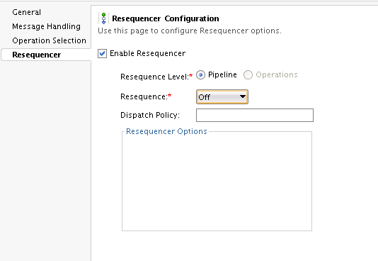
To enable resequencing in a pipeline:
16.11.2 Selecting the Resequence Level in JDeveloper
You can define resequencing either at the pipeline level or the operation level. The Resequence Level can have the following values:
-
Pipeline: A common configuration specified at the component level is used to resequence all messages. If a component has multiple operations, then messages for each operation are sequenced separately using the common component configuration.
Component-level resequencing is allowed only when all the operations of the pipeline component support request one-way messages. If only a subset of operations support request one-way messages, then you can individually specify operation-level resequencing for these operations.
-
Operations: For a WSDL-based pipeline, resequencing can be configured at the operation level. Each operation can have a different resequencer configuration. Only operations supporting request one-way messages can be resequenced. Non-WSDL pipelines cannot have resequencer configured at the operation level.
16.11.3 How to Configure the Resequencing Mode in JDeveloper
This section provides instructions on how to configure various resequencing modes. See "Resequencing Order" in Developing SOA Applications with Oracle SOA Suite to learn about the various resequencing modes. By default, the group ID has a character limit of 1000; the ID has a character limit of 100.
16.11.3.1 Configuring a Standard Resequencer
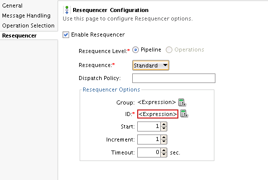
To configure a standard resequencer:
Table 16-1 Standard Resequencing Options
| Field Name | Description | Default Value | Mandatory |
|---|---|---|---|
|
Group |
An XQuery expression that points to the field in the incoming message on which grouping is done. If you do not enter a value, then all messages are put in one default group. Click the Expression Builder icon on the right to invoke the XQuery Expression Builder. |
N/A |
N |
|
ID |
An XQuery expression that points to the field in the incoming message on which resequencing is done. Click the Expression Builder icon on the right to invoke the XQuery Expression Builder. |
N/A |
Y |
|
Start |
The starting number of the ID sequence. |
1 |
N |
|
Increment |
The increment of the ID sequence. |
1 |
N |
|
Timeout |
The time period in seconds to wait for an expected message. The resequencer locks the group as timed-out if a time out occurs. The default value of 0 means that the timeout never happens for a group by default. |
0 |
N |


