13 Working with Pipelines in Oracle Service Bus Console
This chapter describes how to create and configure pipelines, or message flows, using the Oracle Service Bus Console. Sections include adding and configuring pipeline pairs, conditional branches, stages, operational branches, and route nodes.
For more detailed information on pipelines and their components, see Modeling Message Flow in Oracle Service Bus.
13.1 Introduction to the Oracle Service Bus Console Pipeline Designer
The pipeline designer provides a graphical representation of the message flow as you create and configure actions.
13.1.1 Edit Message Flow Page on the Console
Use the Edit Message Flow page to construct a message flow for a pipeline.
The left navigation pane of the Edit Message Flow page shows a tree view of the nodes and objects in the pipeline. When the details of an object are defined on a separate page, you can click the name of the object to display the associated page.
The right pane provides a field upon which to construct the pipeline. When a message flow has not yet been defined, the pane includes a single Pipeline icon that signifies the starting node for the pipeline. Click the icon to add pipeline pair nodes, route nodes, conditional branches, operational branches, and error handling for the service.
When you add objects to the page, icons are displayed on the page to represent the objects. The relationships among the objects are shown with lines and bounding boxes. Click an icon on the Edit Message Flow page to display a menu of the actions you can perform on that object. The options available on the menu may differ, depending on context. See Table 13-1 for a complete list of icons and options.
Table 13-1 Edit Message Flow Page Icons and Options
| Icon | Description | Menu Options |
|---|---|---|
|
Pipeline |
The starting node for the pipeline. |
|
|
Pipeline Pair Node |
A pipeline pair node consists of a request pipeline and a response pipeline. |
|
|
Response Pipeline |
See pipeline pair node above. |
|
|
Request Pipeline |
See pipeline pair node above. |
|
|
Pipeline with Error Handler |
A pipeline with an error handler defined for it. |
|
|
Route Node |
Route node actions define the handling of messages as they flow through the route node. |
|
|
Route Node with Error Handler |
A route node with an error handler defined for it. |
|
|
Stage Node |
A stage node is a container of actions. |
|
|
Stage Node with Error Handler |
A stage node with an error handler defined for it. |
|
|
Conditional Branch Node |
A conditional branch node allows processing to proceed down exactly one of several possible paths. |
|
|
Operational Branch Node |
An operational branch node determines what branch to follow based on specified operations. |
|
|
REST Branch Node |
A REST branch determines what branch to follow based on media type consumed, relative URI, or HTTP Verb. |
|
|
Branch Node |
A branch node is one of the alternative nodes defined by a conditional branch node, an operational branch node, or a REST branch node. |
|
|
Error Handler |
An error handler provides the logic for resending errors in the pipeline. |
|
13.1.2 Edit Stage Configuration Page on the Console
Use the Edit Stage Configuration page to add actions to pipeline stages, error handler stages, and route nodes in a pipeline.
-
When nothing has yet been defined on the Edit Stage Configuration page, the only object displayed is the Add an Action icon. Click that icon to get started.
-
When a stage or a route node has already been configured, the actions and objects defined for that stage or route node appear on the page. Edit the existing actions, as appropriate, or click any of the icons representing actions to add more actions to the stage.
See Adding and Editing Pipeline Actions in the Console for instructions on working with all the kinds of actions you can add to a stage.
13.2 Viewing and Editing Pipelines in the Console
The pipeline designer opens in a new browser window when you launch it from the n the Oracle Service Bus Console.
13.2.1 How to View and Edit Pipelines in the Console
Perform the following steps to access the pipeline designer from the Oracle Service Bus Console.
To view and edit pipelines in the console:
13.2.2 How to Add Shared Variables to Pipelines in the Console
If two pipelines in a single call chain declare the same shared variable, then they read and modify the same variable in the scope of the invocation call chain. In other words, if pipeline P1 declares a shared variable var, and pipeline P1 invokes pipeline P2, which also declares a shared variable var, then any changes to var in P1 are visible in P2, and vice versa. A shared variable must be of the String, Boolean, or XML data type.
When a pipeline receives and processes a message, all invoked pipelines that use a shared variable, read and write the same value for the variable. A subsequent message received by the proxy creates a new instance of the shared variable in the invoked pipelines.
Shared variables work across local proxy invocations and split-join component invocations. For example, say pipelines P1 and P2 declare a shared variable. Now, if P1 invokes a local proxy service or split-join component, which in turn invokes P2, then P1 and P2 continue to share the shared variable.
The following restrictions apply to using shared variables:
-
System variables (such as
$body, $attachments, $operation, $inbound, $outbound) cannot be shared. -
Variables cannot be shared across non-local proxy invocations. For example, say a pipeline invokes an HTTP proxy service, the shared variable is not propagated across this call.
-
Variables cannot be shared between pipeline and split-join resources.
-
Variables with Java and binary content types are not supported. For example, an XML-typed variable that has
<ctx:java-content/>in its XML structure, is not supported as a shared variable.
Before you begin
These instructions assume you are already editing a pipeline in the Edit Message Flow page, as explained in Viewing and Editing Pipelines in the Console.
To add a shared variable to a pipeline:
- Click Expand Shared Variables section to expand the Shared Variables section at the top left hand corner of the Edit Message Flow page.
- Enter a name for the shared variable in the Variable field.
- Click Add to add the shared variable to the pipeline.
13.2.3 How to Add Pipeline Pairs to Pipelines
A pipeline can include zero or more pipeline pair nodes: request and response pipelines for the pipeline (or for the operations on the service), and error handler pipelines that can be defined for stages, pipelines, and the service. Pipelines can include one or more stages, which in turn include actions.
Before you begin
These instructions assume you are already editing a pipeline in the Edit Message Flow page, as explained in Viewing and Editing Pipelines in the Console.
To add a pipeline pair to a pipeline:
-
Click the Pipeline icon, then click Add Pipeline Pair.
-
To change the default name and add a description for the pipeline pair node, do the following:
-
Click the Pipeline Pair Node icon, then click Edit Name and Comments.
-
Change the name and description, as desired.
-
Click Save.
Note:
When you rename a pipeline or a route node, the number of messages displayed on the Dashboard page in the Monitoring module may not correlate with those of other components due to the pipeline counters being reset to zero. This is because Service Bus treats the rename as a delete and recreate action. The numbers should correlate again after a time period equal to the service's monitoring interval has elapsed.
-
-
To add stages to the pipeline, see How to Add Stages to Pipelines in the Console.
-
To add actions to stages in the pipeline. See Adding and Editing Pipeline Actions in the Console.
-
Click Save to commit the updates in the current session.
-
To end the session and deploy the configuration to the runtime, click Activate in the top right corner of the Oracle Service Bus Console window.
13.2.4 How to Add Conditional Branches to Pipelines in the Console
A branch node allows processing to proceed along exactly one of several possible paths. Branching is driven by an XPath-based switch table. Each branch in the table specifies a condition (for example, <500) that is evaluated in order down the pipeline against a single XPath expression (for example, ./ns: PurchaseOrder/ns:totalCost on $body). Whichever condition is satisfied first determines which branch is followed. If no branch condition is satisfied, then the default branch is followed. A branch node may have several descendants in the pipeline: one for each branch, including the default branch.
If the proxy service is not based on a WSDL file and receives multiple document types as input, consider using a conditional branch node.
Conditional branching is driven by a lookup table with each branch tagged with a simple, but unique, string value. A variable in the message context is designated as the lookup variable for that node, and at runtime, its value is used to determine which branch to follow. If no branch matches the value of the lookup variable, the default branch is followed. You should design the pipeline in such a way that the value of the lookup variable is set before reaching the branch node.
Before you begin
These instructions assume you are already editing a pipeline in the Edit Message Flow page, as explained in Viewing and Editing Pipelines in the Console.
To add a conditional branch to a pipeline:
-
Click a Pipeline Pair Node icon or a Branch Node icon, then click Create Conditional Branch. The conditional branch node is added, and any existing nodes after the inserted branch node are moved to the default branch of the new conditional branch node.
-
To change the default name and add a description for the branch node, do the following:
-
Click the Conditional Branch icon, then click Edit Name and Comments.
-
Change the name and description, as desired.
-
Click Save.
-
-
To add branch definitions, click the Conditional Branch icon, then click Edit Branch. The Edit Branch Node page is displayed.
-
Do the following:
-
In the Selected Path field, click Edit to add an XPath expression for specifying the path. See Creating and Editing Inline XQuery and XPath Expressions.
-
In the Variable field, enter a context variable.
-
From the Operator field, select a comparison operator.
-
In the Value field, enter a value for the branch.
-
In the Label field, enter a label for the branch.
-
-
Optionally, under Options:
-
Click Add a New Branch to add a new branch definition to this branch node.
-
Click Delete this Branch to delete a branch definition.
-
Click Move Branch Up or click Move Branch Down to change the positions of branch definitions. This option displays only when more than one branch definition exists.
-
-
Click Save to commit the updates in the current session.
-
On the Edit Message Flow page, continue to construct the pipeline, as described in Viewing and Editing Pipelines in the Console.
-
Click Save to commit the updates in the current session.
-
To end the session and deploy the configuration to the runtime, click Activate in the top left corner of the Oracle Service Bus Console window.
13.2.5 How to Add Operational Branches to Pipelines in the Console
When pipelines define Web Services Description Language (WSDL)-based proxy services, operation-specific processing is required. Instead of configuring a branching node based on operations manually, Service Bus provides a minimal configuration branching node that automatically branches based on operations. In other words, when you create an operational branch node in a pipeline, you can quickly build your branching logic based on the operations defined in the WSDL file because the Oracle Service Bus Console presents those operations in the branch node configuration page.
A branch node allows processing to proceed along exactly one of several possible paths. Branching is driven by an XPath-based switch table. Each branch in the table specifies a condition (for example, <500) that is evaluated in order down the pipeline against a single XPath expression (for example, ./ns: PurchaseOrder/ns:totalCost on $body). Whichever condition is satisfied first determines which branch is followed. If no branch condition is satisfied, then the default branch is followed. A branch node may have several descendants in the pipeline: one for each branch, including the default branch.
Before you begin
These instructions assume you are already editing a pipeline in the Edit Message Flow page, as explained in Viewing and Editing Pipelines in the Console.
To add an operation branch to a pipeline:
-
Click a Pipeline Pair Node icon or a Branch Node icon, then click Create Operational Branch. The operational branch node is added, and any existing nodes after the inserted branch node are moved to the default branch of the new operational branch node.
-
To change the default name and add a description for the branch node, do the following:
-
Click the Operational Branch icon, then click Edit Name and Comments.
-
Change the name and description, as desired.
-
Click Save.
-
-
To add branch definitions, click the Operational Branch icon, then click Edit Branch. The Edit Branch Node page is displayed.
-
In the Operation Branch Definitions panel, select a service operation.
-
Optionally, under Options:
-
Click Add a New Branch to add a new branch definition to this branch node.
-
Click Delete this Branch to delete a branch definition.
-
Click Move Branch Up or click Move Branch Down to change the positions of branch definitions. This option displays only when more than one branch definition exists.
-
-
Click Save.
-
On the Edit Message Flow page, continue to construct the pipeline, as described in Viewing and Editing Pipelines in the Console.
-
Click Save to commit the updates in the current session.
-
To end the session and deploy the configuration to the runtime, click Activate in the top left corner of the Oracle Service Bus Console window.
13.2.6 How to Add REST Branches to Pipelines in the Console
These instructions assume you are already editing a pipeline in the Edit Message Flow page, as explained in Viewing and Editing Pipelines in the Console.
13.2.7 How to Add Stages to Pipelines in the Console
Before you begin
These instructions assume you are already editing a pipeline in the Edit Message Flow page, as explained in Viewing and Editing Pipelines in the Console.
To add a stage to a pipeline:
-
If necessary, click the plus sign to the left of the Pipeline Pair Node icon to expand it. A pipeline pair contains a Request Pipeline and a Response Pipeline.
-
Click the pipeline to which you want to add the stage, then click Add Stage.
-
To change the default name and add a description for the stage, do the following:
-
Click the Stage icon, then click Edit Name and Comments.
-
Change the name and description, as desired.
-
Click Save.
-
-
To add actions to the stage, click the Stage icon, then click Edit Stage. See Adding and Editing Pipeline Actions in the Console.
-
To add error handling to the stage, click the Stage icon, then click Add Stage Error Handler. See Adding Error Handlers in the Console. The Edit Message Flow page is displayed.
-
Continue to construct the pipeline, as described in Viewing and Editing Pipelines in the Console.
-
Click Save to commit the updates in the current session.
-
To end the session and deploy the configuration to the runtime, click Activate in the top right corner of the Oracle Service Bus Console window.
13.2.8 How to Add Route Nodes to Pipelines in the Console
Before you begin
These instructions assume you are already editing a pipeline in the Edit Message Flow page, as explained in Viewing and Editing Pipelines in the Console.
To add a route node to a pipeline:
13.3 Cutting, Copying, and Pasting Stages and Route Nodes
You can cut, copy, and paste stages and route nodes.
-
To cut a stage or a route node, click its icon and select Cut or Copy.
-
To paste a stage that you cut or copied from a different pipeline pair within the message flow of this pipeline or from the message flow of a different pipeline, do one of the following:
-
Click the Request Pipeline or Response Pipeline icon, then click Paste Stage.
-
Click a Stage icon in a pipeline, then click Paste.
-
-
To paste a route node that you cut or copied from another pipeline, click the Pipeline Pair Node icon for the pipeline pair, then click Paste Route.
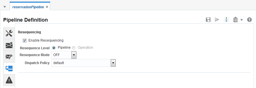
13.4 Configuring the Resequencer in the Console
The resequencer in Service Bus rearranges a stream of related but out-of-sequence messages into a sequential order.
When incoming messages arrive, they can be in a random order. The resequencer orders the messages based on sequential or chronological information, and then sends the messages to the target services in an orderly manner. The sequencing is performed based on the sequencing strategy selected.
You can configure the resequencer inside a pipeline component. Pipelines with the following service types are supported:
-
WSDL: Resequencing is available for operations with only request type.
-
Message Type: The request message type must be XML, and the response message type must be None.
Note:
The resequencer does not support Any XML and Any SOAP service types. For WSDL-based services, the WSDL file must be one-way; that is, it cannot contain output elements. For information about using generated WSDL files with resequencing pipelines, see How to Export a WSDL File in the Console.
13.4.1 How to Configure Resequencing in a Pipeline in the Console
This section describes how to configure the resequencer in a pipeline using Oracle Service Bus Console.
To enable resequencing in a pipeline component:
13.4.2 How to Select the Resequence Level in the Console
You can define resequencing either at the pipeline level or the operation level. The Resequence Level can have the following values:
-
Pipeline: A common configuration specified at the component level is used to resequence all messages. If a component has multiple operations, then messages for each operation are sequenced separately using the common component configuration.
Component-level resequencing is allowed only when all the operations of the pipeline component support request one-way messages. If only a subset of operations support request one-way messages, then you can individually specify operation-level resequencing for these operations.
-
Operation: For a WSDL-based pipeline, resequencing can be configured at the operation level. Each operation can have a different resequencer configuration. Only operations supporting request one-way messages can be resequenced. Non-WSDL pipelines cannot have resequencer configured at the operation level.
13.4.3 How to Configure the Resequencing Mode in the Console
This section provides instructions on how to configure various resequencing modes. See "Resequencing Order" in Developing SOA Applications with Oracle SOA Suite to learn about the various resequencing modes. By default, the group ID has a character limit of 1000; the ID has a character limit of 100.
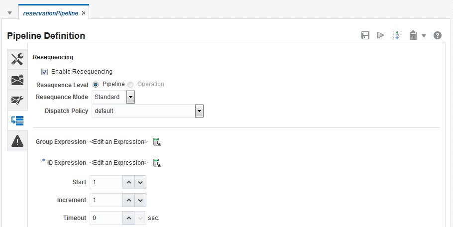
13.4.3.1 Configuring a Standard Resequencer
To configure a standard resequencer:
Table 13-2 Standard Resequencing Options
| Field Name | Description | Default Value | Mandatory |
|---|---|---|---|
|
Group Expression |
An XQuery expression that points to the field in the incoming message on which grouping is done. If you do not enter a value, then all messages are put in one default group. Click the Expression Builder icon on the right to invoke the XQuery/XSLT Expression Editor. |
N/A |
N |
|
ID Expression |
An XQuery expression that points to the field in the incoming message on which resequencing is done. Click the Expression Builder icon on the right to invoke the XQuery/XSLT Expression Editor. |
N/A |
Y |
|
Start |
The starting number of the ID sequence. |
1 |
N |
|
Increment |
The increment of the ID sequence. |
1 |
N |
|
Timeout |
The time period in seconds to wait for an expected message. The resequencer locks the group as timed-out if a time out occurs. The default value of 0 means that the timeout never happens for a group by default. |
0 |
N |
Note:
In the standard resequencer use cases in which the time interval between the right message sequences vary significantly, configuring the right timeout value may not be always feasible. Configuring a lower resequencer time out value may result in that group getting timed out and the resequencer not processing subsequent messages. You can set the value to "0" in such situations. Configuring these system properties could also improve the overall performance of the resequencer in such cases.
-Dweblogic.threadpool.MinPoolSize=100 -Dresequencer.containerIdRefresh.time=120
13.5 Creating Variable Structure Mappings
These sections describe how to create several types of variable structure mappings.
13.5.1 Sample WSDL Document
This sample WSDL document is used in most of the examples in this section. You need to save this WSDL document as a resource in your configuration. For more information, see Creating the Resources You Need for the Examples.
Example - Sample WSDL Document
<definitions
    name="samplewsdl"
    targetNamespace="http://example.org"
    xmlns="http://schemas.xmlsoap.org/wsdl/"
    xmlns:s0="http://www.oracle.com"
    xmlns:s1="http://example.org"
    xmlns:soap="http://schemas.xmlsoap.org/wsdl/soap/">
<types>
  <xs:schema
    attributeFormDefault="unqualified"
    elementFormDefault="qualified"
    targetNamespace="http://www.oracle.com"
    xmlns:xs="http://www.w3.org/2001/XMLSchema">
    <xs:element name="PO" type="s0:POType"/>
    <xs:complexType name="POType">
      <xs:all>
        <xs:element name="id" type="xs:string"/>
        <xs:element name="name" type="xs:string"/>
      </xs:all>
    </xs:complexType>
    <xs:element name="Invoice" type="s0:InvoiceType"/>
    <xs:complexType name="InvoiceType">
      <xs:all>
        <xs:element name="id" type="xs:string"/>
        <xs:element name="name" type="xs:string"/>
      </xs:all>
    </xs:complexType>
</xs:schema>
</types>
<message name="POTypeMsg">
    <part name="PO" type="s0:POType"/>
</message>
<message name="InvoiceTypeMsg">
    <part name="InvReturn" type="s0:InvoiceType"/>
</message>

<portType name="POPortType">
    <operation name="GetInvoiceType">
      <input message="s1:POTypeMsg"/>
      <output message="s1:InvoiceTypeMsg"/>
    </operation>
</portType>
<binding name="POBinding" type="s1:POPortType">
<soap:binding style="rpc" transport="http://schemas.xmlsoap.org/soap/http"/>
    <operation name="GetInvoiceType">
      <soap:operation soapAction="http://example.com/GetInvoiceType"/>
      <input>
        <soap:body use="literal"/>
      </input>
      <output>
        <soap:body use="literal"/>
    </output>
  </operation>
</binding>
</definitions>
13.5.2 Creating the Resources You Need for the Examples
To make use of the examples that follow, save the sample WSDL document as a resource in your configuration and create the sample business service and proxy service that use the sample WSDL document.
The instructions that follow tell how to accomplish the tasks in the Oracle Service Bus Console:
13.5.2.1 Save the WSDL File as a Resource
Perform the following steps:
- If you have not already done so, click Create to create a new session or click Edit to enter an existing session.
- From the top right of the Oracle Service Bus Console window, click the Designer tab. The Project Navigator appears.
- Expand the All Projects node by clicking the Expand (arrow) icon before it.
- Right-click the project name to which you wish to add the WSDL file. From the context menu, click Create, and then click Resource.
- From the Resource Gallery, click Interfaces, and then click WSDL. The Create WSDL dialog appears.
- In the Resource Name field, enter
SampleWSDL. This is a required field. - In the Description field, enter a description for the WSDL resource. This is optional.
- Click Choose File and select the WSDL sample file.
- Click Create to create the WSDL resource.
13.5.2.2 Create a Proxy Service and Pipeline
Perform the following steps to create a proxy service and pipeline that use the sample WSDL document:
13.5.2.3 Build a Message Flow for the Sample Pipeline
Perform the following steps:
- In the Project Navigator, click the pipeline
PipelinewithSampleWSDLto open it. - Click the Open Message Flow icon, in the top right corner, to start editing the message flow for the pipeline. The Edit Message Flow page appears.
- In the Edit Message Flow page, click the
PipelinewithSampleWSDLicon, then click Add Pipeline Pair. PipelinePairNode1 is displayed, which includes request and response pipelines. - Click the Request Pipeline icon, then click Add Stage. The Stage Stage1 is displayed.
- Click Save. The basic message flow is created for the
PipelinewithSampleWSDLpipeline.
13.5.3 Example 1: Selecting a Predefined Variable Structure
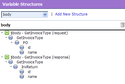
In this example, you select a predefined variable structure using the proxy service ProxyWithSampleWSDL, which has a service type WSDL Web Service that uses the binding POBinding from SampleWSDL.
The pipeline message flow needs to know the structure of the message in order to manipulate it. To achieve this, Service Bus automatically provides a predefined structure that maps the body variable to the SOAP body structure as defined by the WSDL file of the proxy service for all the messages in the interface. This predefined structure mapping is labeled body.
Note:
This predefined structure is also supported for messaging services with a typed interface.
To select a predefined variable structure:
In the Variable Structures panel on the XQuery Expression Editor page, select body from the list of built-in structures.
The variable structure body is displayed in Figure 13-3.
13.5.4 Example 2: Mapping a Variable to a Type
Suppose the proxy service ProxyWithSampleWSDL invokes a service callout to the business service BusinessWithSampleWSDL, which also has a service type WSDL Web Service that uses the binding POBinding from SampleWSDL. The operation GetInvoiceType is invoked.
In this example, the pipeline needs to know the structure of the response parameter in order to manipulate it. To achieve this, you can create a new variable structure that maps the response parameter variable to the type InvoiceType.
To map a variable to a type:
-
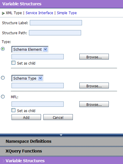
In the Variable Structures panel, click Add New Structure. Additional fields are displayed in Figure 13-4.
Figure 13-4 Variable Structures—Add a New Structure
Description of "Figure 13-4 Variable Structures—Add a New Structure" -
Select the XML Type.
-
In the Structure Label field, enter
InvoiceTypeas the display name for the variable structure you want to create. This display name enables you to give a meaningful name to the structure so you can recognize it at design time but it has no impact at runtime. -
In the Structure Path field, enter
$InvoiceTypeas the path of the variable at runtime. -
To select the type InvoiceType, do the following:
-
Under the Type field, select the appropriate radio button, then select WSDL Type from the list.
-
Click Browse. The WSDL Browser is displayed.
-
In the WSDL Browser, select SampleWSDL, then select InvoiceType under Types in the Select WSDL Definitions pane.
-
Click Submit. InvoiceType is displayed under your selection WSDL Type.
-
-
Click Add. The new variable structure InvoiceType is included under XML Type in the list of variable structures.
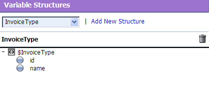
The variable structure InvoiceType is displayed in Figure 13-5.
Figure 13-5 Variable Structures—InvoiceType
Description of "Figure 13-5 Variable Structures—InvoiceType"
13.5.5 Example 3: Mapping a Variable to an Element
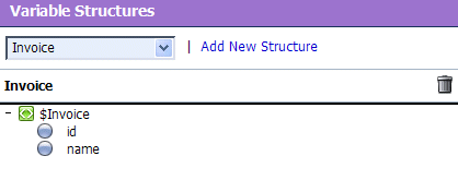
Suppose a temporary variable has the element Invoice described in the SampleWSDL WSDL file. In this example, the ProxyWithSampleWSDL pipeline needs to access this variable. To achieve this, you can create a new variable structure that maps the variable to the element Invoice.
To map a variable to an element:
-
In the Variable Structures panel, click Add New Structure.
-
Make sure you select the XML Type.
-
In the Structure Label field, enter
Invoiceas the meaningful display name for the variable structure you want to create. -
In the Structure Path field, enter
$Invoiceas the path of the variable structure at runtime. -
To select the element Invoice, do the following:
-
For the Type field, make sure you select the appropriate radio button.Then select WSDL Element.
-
Click Browse.
-
In the WSDL Browser, select
SampleWSDL, then select Invoice under Elements in the Select WSDL Definitions pane. -
Click Submit. Invoice is displayed under your selection WSDL Element.
-
-
Click Add. The new variable structure Invoice is included under XML Type in the list of variable structures.
The variable structure Invoice is displayed in Figure 13-6.
13.5.6 Example 4: Mapping a Variable to a Child Element
The ProxyWithSampleWSDL proxy service routes to the document style Any SOAP business service that returns the Purchase Order in the SOAP body. In this example, the ProxyWithSampleWSDL pipeline must then manipulate the response. To achieve this, you can create a new structure that maps the body variable to the PO element, and specify the PO element as a child element of the variable. You need to specify it as a child element because the body variable contains the SOAP Body element and the PO element is a child of the Body element.
To map a variable to a child element:
-
In the Variable Structures panel, click Add New Structure.
-
Make sure you select the XML Type.
-
In the Structure Label field, enter
body toPOas the meaningful display name for the variable structure you want to create. -
In the Structure Path field, enter
$bodyas the path of the variable structure at runtime. -
To select the PO element:
-
Under the Type field, make sure you select the appropriate radio button, and then select WSDL Element.
-
Click Browse.
-
In the WSDL Browser, select
SampleWSDL, then select PO under Elements in the Select WSDL Definitions pane. -
Click Submit.
-
-
Select the Set as child check box to set the
POelement as a child of the body toPOvariable structure. -
Click Add. The new variable structure body to PO is included under XML Type in the list of variable structures.
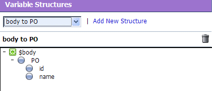
The variable structure body to PO is displayed in Figure 13-7.
Figure 13-7 Variable Structures—body to PO
Description of "Figure 13-7 Variable Structures—body to PO"
13.5.7 Example 5: Mapping a Variable to a Business Service
The ProxyWithSampleWSDL proxy service routes the message to the BusinessWithSampleWSDL business service, which also has a service type WSDL Web Service that uses the binding POBinding from SampleWSDL. In this example, the pipeline must then manipulate the response. To achieve this, you can define a new structure that maps the body variable to the BusinessWithSampleWSDL business service. This results in a map of the body variable to the SOAP body for all the messages in the WSDL interface of the service.
Note:
This mapping is also supported for messaging services with a typed interface.
To map a variable to a business service:
-
In the Variable Structures panel, click Add New Structure.
-
Select Service Interface.
-
In the Structure Label field, enter
BusinessServiceas the meaningful display name for the variable structure. -
In the Structure Path field,
$bodyis already set as the default. This is the path of the variable structure at runtime. -
To select the business service, do the following:
-
Under the Service field, click Browse. The Service Browser is displayed.
-
In the Service Browser, select the
BusinessWithSampleWSDLbusiness service, then click Submit. The business service is displayed under the Service field. -
In the Operation field, select All.
-
-
Click Add. The new variable structure
BusinessServiceis included under Service Interface in the list of variable structures.The variable structure
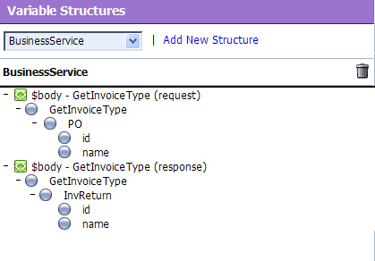
BusinessServiceis displayed in Figure 13-8.
Figure 13-8 Variable Structures—Business Service
Description of "Figure 13-8 Variable Structures—Business Service"
13.5.8 Example 6: Mapping a Child Element to Another Child Element
Modify the SampleWSDL so that the ProxyWithSampleWSDL proxy service receives a single attachment. The attachment is a Purchase Order. In this example, the pipeline must then manipulate the Purchase Order. To achieve this, you can define a new structure that maps the body element in $attachments to the PO element, which is specified as a child element. The body element is specified as a variable path of the form:
$attachments/ctx:attachment/ctx:body
You can select and copy the body element from the predefined attachments structure, paste this element as the variable path to be mapped in the new mapping definition.
To map a child element to another child element:
-
In the Variable Structures panel, select attachments from the list of built-in structures.
The variable structure attachments is displayed in Figure 13-9.
Figure 13-9 Variable Structures—attachments
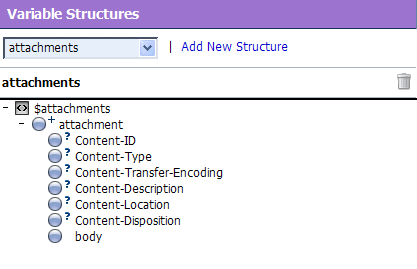
Description of "Figure 13-9 Variable Structures—attachments" -
Select the
bodychild element in the attachments structure. The variable path of the body element is displayed in the Property Inspector on the right side of the page:$attachments/ctx:attachment/ctx:body
-
Copy the variable path of the
bodyelement. -
In the Variable Structures panel, click Add New Structure.
-
Select the XML Type.
-
In the Structure Label field, enter
POattachmentas the meaningful display name for this variable structure. -
In the Structure Path field, paste the variable path of the body element:
$attachments/ctx:attachment/ctx:body
This is the path of the variable structure at runtime.
-
To select the
POelement:-
Under the Type field, make sure the appropriate radio button is selected, then select WSDL Element.
-
Click Browse.
-
In the WSDL Browser, select
SampleWSDL, then select PO under Elements in the Select WSDL Definitions pane. -
Click Submit.
-
-
Select the Set as child check box to set the PO element as a child of the body element.
-
Click Add. The new variable structure PO attachment is included under XML Type in the list of variable structures.
-
If there are multiple attachments, add an index to the reference when you use fields from this structured variable in your XQueries. For example, if you drag the PO field to the XQuery field, but as PO will be the second attachment, change the inserted value from
$attachments/ctx:attachment/ctx:body/oracle:PO/oracle:id
to
$attachments/ctx:attachment[2]/ctx:body/oracle:PO/oracle:id
