Message Designer
This chapter covers the following topics:
- Message Designer Overview
- Message Designer Wizards
- Using the Data Definition Creation Wizard
- Using the Map Creation Wizard
- Transaction Map Window
- Map Action Editor
- How to Extend DTDs
- How to Map a Pass-Through Message
- How to Map to an API
- Loading and Deleting Message Maps and DTDs
- Downloading a Map
- Loading and Deleting an XSLT Style Sheet
- How to Implement Attachments in XML Messages
Message Designer Overview
The Message Designer is a wizard-guided, repository-based tool used to create XML message maps. Map creation consists of defining the data source and data target, defining hierarchy and data maps between the source and target data, and defining actions for data transformation and process control.
The Message Designer is independent of XML standards. It complies with version 1.0 of the W3C XML specifications.
Note: Information regarding the W3C XML Standards can be found at http://www.w3.org/XML/Activity.
The Message Designer can support map creation for any business document as long as the document conforms to a Document Type Definition (DTD).
The Message Designer can be used to:
-
Modify the Oracle prebuilt message maps
-
Create new message maps
If you are using the Message Designer to create new message maps, you must complete a map analysis before attempting to use the Message Designer. Refer to Map Analysis Guidelines for the details. The thoroughness of your map analysis will impact the success of your map creation.
Load completed message maps and associated DTDs into the XML Gateway repository. The XML Gateway Execution Engine and the XML Parser use the maps to create outbound messages and to consume inbound XML messages.
Message Designer Menus
The Message Designer has the following menus: File, View, and Help. Some of the menu functions can also be accessed by toolbar icons.
See: Message Designer Toolbar.
File Menu
Use the Message Designer to create new data definitions and transaction maps or to modify existing data definitions and transaction maps.
The Message Designer supports the following file types:
-
XGD for source or target data definitions
-
XGM for transaction maps
The .XGD and .XGM files are XML files that can be opened and read using a browser or any XML editor. The XGD and XGM files are used to describe the structure and content of a message. The XML message produced or consumed using the transaction map (XGM) contains the actual business data.
The File menu options are listed in the following table:
| Menu Option | Description |
|---|---|
| New | Create a new data definition file or a new transaction map file. |
| Open | Open an existing file. Files can be either data definition files with a XGD extension, or transaction map files with a XGM extension. |
| Close | Close the open transaction map or data definition file. |
| Save | Save an open file. Save the data definition files as XGD files. Save the transaction map files as XGM files. |
| Properties | Provides access to key property values entered using the Data Definition Creation Wizard or Map Creation Wizard. Use this menu option to change any of the original key values presented. See File > Properties Menu Option for more details regarding this menu option. |
| Exit | Exit Message Designer. |
View Menu
Use the View Menu to view the source or target definitions in tree format only, table format only, or both tree and table formats.
The View menu options are listed in the following table:
| Menu Option | Description |
|---|---|
| Tree | View source or target definition in tree format only. |
| Table | View source or target definition in table format only. |
| View Both | View source or target definition in both tree and table formats. This is the default viewing option. |
Help Menu
The Help menu options are listed in the following table:
| Menu Option | Description |
|---|---|
| Help Topics | Displays Message Designer help. |
| About | Displays the Message Designer version. |
Message Designer Toolbar
The Message Designer toolbar uses the following icons to duplicate the noted menu options:
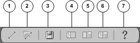
-
Create New Map icon. Invokes the Map Creation Wizard.
-
Open Map icon. Opens an existing map.
-
Save Map Icon. Saves the data definition as a XGD file. Saves the transaction map as a XGM file.
-
View Tree icon. Displays the tree format only.
-
View Table icon. Displays the table format only.
-
View Both Tree and Table icon. Displays both the tree and table formats.
-
Help icon. Invokes Message Designer Help.
Message Designer Buttons

The Add Sibling Button adds a new element at the same hierarchy level as the selected item on the map.
For additional information on this function, see the following:
For Source Data Definitions see (Source Definition Tab) Add Sibling.
For Target Data Definitions see (Target Definition Tab) Add Sibling.

The Add Child button adds a new element at a lower hierarchy level than the selected item on the map.
For additional information on this function, see the following:
For Source Data Definitions see (Source Definition Tab) Add Child.
For Target Data Definitions see (Target Definition Tab) Add Child.

The Delete button deletes any element that has not been mapped. Be careful not to delete required data elements. Deleting required elements will cause a parser violation.
If an item has child elements associated with it, a warning is displayed before the delete occurs.
Important: If you are deleting any DTD extensions, be sure to remove the DTD extensions from the corresponding extension file created for the application or user. The extra information will not cause a parser violation, but it is a good practice to ensure the extension files match the message maps. Refer to How to Extend DTDs for the details.
File > Properties Menu
The File > Properties menu option provides access to key property values entered using the Data Definition Creation Wizard or the Map Creation Wizard. Use the Properties window to change any of the key property values presented.
The Property Tabs and fields associated with each Tab vary depending on where the File > Properties menu option is invoked. The options available from each window are:
-
Main Message Designer - General Tab, Database Tab
-
Data Definition Window - General Tab, Database Tab, Data Tab
-
Transaction Map Window- General Tab, Database Tab, Map Tab, Source Tab, Target Tab
General Tab
The General Tab allows you to update the Output Directory. This is the default directory used to store the data definition and message map files created using the Message Designer.
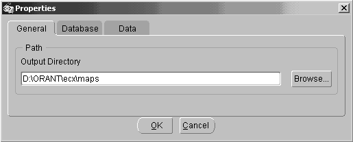
| Variable | Description |
|---|---|
| Output Directory | Use the Browse button to select a default directory or enter a valid directory name. |
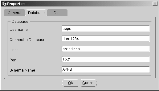
Database Tab
Use the Database Tab to provide the default database connection information. The default values will be provided to the Data Definition and Map Creation Wizards as well as to the Procedure Call action.
The database connection fields prompted for are:
-
Username
-
Connect to Database
-
Host
-
Port
-
Schema Name
Data Tab
The Data Tab allows you to update data values originally entered using the Data Definition Creation Wizard. The fields on the tab vary depending on the type of data definition.
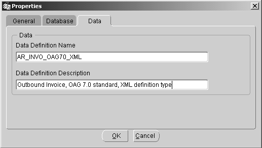
The fields in the following table display for all data definitions:
| Field | Description |
|---|---|
| Data Definition Name | Update the name entered. Observe the naming conventions recommended in the Data Definition and Map Creation Wizards. See Select/Create a Source/Target Data Definition Name and Type for the naming convention details. |
| Data Definition Description | Update the description. |
Important: If the data definition changes affect any existing maps, the maps must be changed and reloaded. If the DTD reference is changed, the new DTD must be reloaded. Refer to How to Load/Delete Message Maps and DTDs.
The fields in the following table display when the data definition type is XML:
| Field | Description |
|---|---|
| Root Element | Update the Root Element entered. The root element entered must match the root element of the DTD entered below. |
| Runtime DTD Location | Update the Runtime DTD Location with the new subdirectory name. Observe the naming conventions recommended in the Data Definition and Map Creation Wizards. See Identify the Runtime Location of a DTD for naming convention details. |
| DTD File Name | Use the Browse button to select a DTD or enter a valid DTD file name. This will replace the file name originally entered. The root element defined in the DTD must match the root element value entered above. |
Important: Changes to any of these property values require the message map to be reloaded. Changing the DTD associated with the message map requires the DTD to be reloaded. Refer to How to Load/Delete Message Maps and DTDs for details.
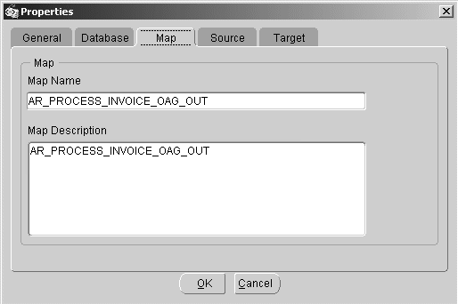
Map Tab
This tab displays only if you are viewing a map transaction file (.XGM).
| Field | Description |
|---|---|
| Map Name | Update the name entered. Observe the naming conventions recommended in the Map Creation Wizard. See Specify a Map Name for details. |
| Map Description | Update the description. |
Important: If the map name change affects any existing Trading Partner definitions, update the Trading Partner definition with the new map name.
Important: The map containing the new name must be reloaded into the XML Gateway repository. Refer to How to Load/Delete Message Maps and DTDs for the details.
Source Tab
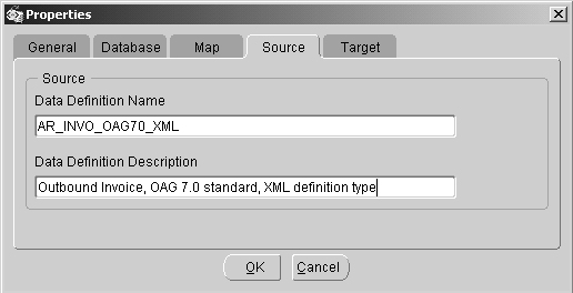
The fields in the following table display for all data definitions:
| Field | Description |
|---|---|
| Data Definition Name | Update the name entered. Observe the naming conventions recommended in the Data Definition and Map Creation Wizards. See Specify Source/Target Data Definition Name and Type for naming convention details. |
| Data Definition Description | Update the description. |
Important: If the data definition changes affect any existing maps, the maps must be changed and reloaded. If the DTD reference is changed, the new DTD must be reloaded. Refer to How to Load/Delete Message Maps and DTDs.
The fields in the following table display when the data definition type is XML:
| Field | Description |
|---|---|
| Root Element | Update the Root Element entered. The root element entered must match the root element of the DTD entered below. |
| Runtime DTD Location | Update the Runtime DTD Location with the new subdirectory name. Observe the naming conventions recommended in the Data Definition and Map Creation Wizards. See Identify the Runtime Location of a DTD for naming convention details. |
| DTD File Name | Use the Browse button to select a DTD or enter a valid DTD file name. This will replace the file name originally entered. The root element defined in the DTD must match the root element value entered above. |
Important: Changes to any of these property values require the message map to be reloaded. Changing the DTD associated with the message map requires the DTD to be reloaded. Refer to How to Load/Delete Message Maps and DTDs for details.
Target Tab
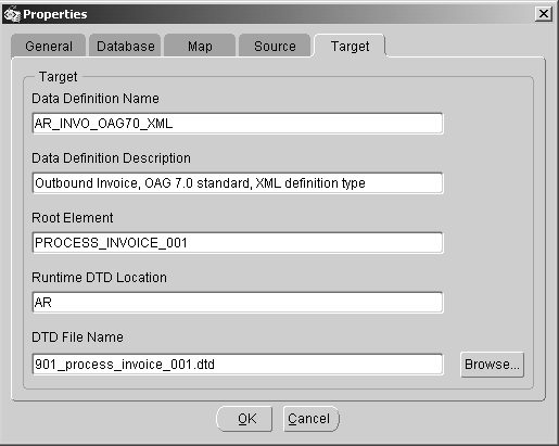
The fields in the following table display for all data definitions:
| Field | Description |
|---|---|
| Data Definition Name | Update the name entered. Observe the naming conventions recommended in the Data Definition and Map Creation Wizards. See Specify Source/Target Data Definition Name and Type for naming convention details. |
| Data Definition Description | Update the description. |
Important: If the data definition changes affect any existing maps, the maps must be changed and reloaded. If the DTD reference is changed, the new DTD must be reloaded. Refer to How to Load/Delete Message Maps and DTDs.
The fields in the following table display when the data definition type is XML:
| Field | Description |
|---|---|
| Root Element | Update the Root Element entered. The root element entered must match the root element of the DTD entered below. |
| Runtime DTD Location | Update the Runtime DTD Location with the new subdirectory name. Observe the naming conventions recommended in the Data Definition and Map Creation Wizards. See Identify the Runtime Location of a DTD for naming convention details. |
| DTD File Name | Use the Browse button to select a DTD or enter a valid DTD file name. This will replace the file name originally entered. The root element defined in the DTD must match the root element value entered above. |
Important: Changes to any of these property values require the message map to be reloaded. Changing the DTD associated with the message map requires the DTD to be reloaded. Refer to How to Load/Delete Message Maps and DTDs for details.
Message Designer Wizards
The Message Designer contains two wizards to guide you through the map creation process. The two wizards are:
-
Data Definition Creation Wizard
-
Map Creation Wizard
The Data Definition Creation Wizard is used to define the data definitions.
A data definition is a collection of data used to describe a business object such as a customer profile or an invoice document. A data definition may be based on database views, database tables, application open interface tables, an application API, an XML Document Type Definition (DTD), or a production XML message.
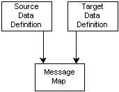
A message map consists of a source data definition and a target data definition graphically represented as follows:
The data definitions created using the Data Definition Creation Wizard are used to create a preliminary message map. The Data Definition Creation Wizard is ideal for creating a master definition to use as the basis for creating trading partner-specific message maps.
Three combinations of source and target data definitions are supported by the Message Designer as described in the following table:
| Source | Target | Purpose |
|---|---|---|
| Database | XML | Outbound XML message |
| XML | Database | Inbound XML message |
| XML | XML | Transform one version of a DTD to the next version of the same DTD. Transform from DTD in one standard to DTD of another standard as long as the DTDs are for the same business function. Pass-through XML message (Refer to How to Map a Pass-Through Message) Mapping to an Application API (Refer to How to Map to an API) |
Database-based data definitions represent a description of the Oracle data model required to support the XML message.
XML-based data definitions are based on an XML Document Type Definition (DTD) or a production XML message. XML to XML transformations from one DTD to another DTD where the DTDs are for different business purposes is done in two steps:
-
Database to XML
-
XML to database
The Map Creation Wizard is used to define the following:
-
Source Definition
-
Target Definition
-
Preliminary Message Map
The source and target data definitions may be new or based on definitions previously created using the Data Definition Wizard. The source and target data definitions form the basis of a preliminary message map.
The Message Designer is used to define the following to complete the message map:
-
Level Mapping
-
Element Mapping
-
Actions
Level mapping is the process of relating the source data structure to the target data structure. Element mapping is the process of relating a source data element to a target data element. Actions are data transformation or process control functions that can be applied at the data element, document, or root level.
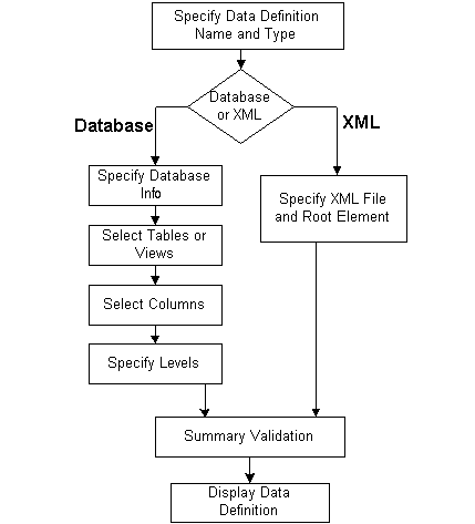
Data Definition Creation Wizard Process Flow
Creating a Data Definition consists of two general steps:
Step 1: Name the data definition and select the type
Step 2: Identify data definition details
The tasks required to complete Step 2 vary depending on your selections in Step 1.
The illustration below displays the flow of the screens presented to you in the Data Definition Creation Wizard. After you specify the data definition name and type (Step 1), you are prompted to provide the details based on whether you chose a type of database or XML.
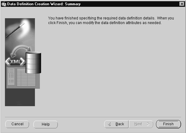
When you have completed Step 2, you are presented with a summary screen where you can either finish or return to previous steps to make edits. Clicking Finish will close the Wizard and open the Message Designer Data Definition window.
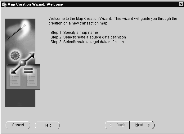
Map Creation Wizard Process Flow
There are three general steps to creating a map. Each step consists of a variable number of tasks depending on the selections you make in the Wizard:
Step 1: Specify a Map Name
Step 2: Select/Create a Source Data Definition
Step 3: Select/Create a Target Data Definition
The illustration below displays the flow of the screens presented to you in the Map Creation Wizard. After you specify a map name (Step 1), you are prompted to select or create a source data definition (Step 2). If you choose to create the data definition, you are guided through the data definition creation steps (identical to the Data Definition Creation Wizard steps).
After you create your source data definition, or if you chose to select an existing data definition, you are prompted to select or create a target data definition (Step 3). The target data definition steps are identical to the source data definition steps.
When you have completed Step 3, you are taken to a summary screen where you can either finish or return to previous steps to make edits.
Using the Data Definition Creation Wizard
The Data Definition Creation Wizard guides you through the data definition creation process. The data definition is saved as a .xgd file and can be selected as a target or a source when you create a map.
Important: It is not necessary to create your data definitions before you begin the map creation process. The Map Creation Wizard gives you the option of choosing an existing data definition or creating a new one. If you choose to create a new one, you will be guided through the data definition creation steps as part of your map creation process. See Map Creation Wizard.
Launch the Data Definition Creation Wizard by selecting
(M) File > New > Data Definition
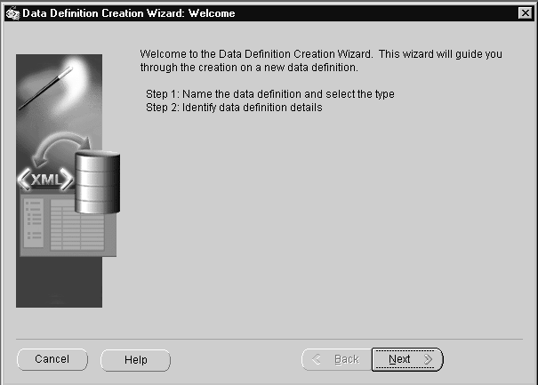
The first window welcomes you to the wizard.
The following buttons are available for all Wizard steps:
-
Cancel
Exit the Wizard and cancel all completed Wizard steps.
-
Back
Return to the previous Wizard step.
-
Next
Advance to the next Wizard step. The Next button is enabled only after the required information for the current Wizard step has been entered.
Data Definition Creation Wizard Steps
Follow the instructions presented for the Map Creation Wizard to complete each of the Data Definition Creation Wizard steps:
Specify Data Definition Name and Type
See Specify Source/Target Data Definition Name and Type.
If you selected Database...
Complete the following steps:
Specify Database Information
See Specify Source/Target Definition Database Information.
Select Tables or Views
See Select Source/Target Tables or Views
Select Columns
See Select Source/Target Columns
Specify Source/Target Levels
See Specify Source/Target Levels.
If you selected XML...
If you selected XML as the data definition type, you will be prompted for the XML information.
See Specify Source/Target XML File and Root Element.
Data Definition Creation Wizard: Summary
Click Finish to complete the Wizard steps. If you wish to change any selections you have made in defining your data definition, you can used the Back button to return to the appropriate Wizard window.
Message Designer Data Definition Window
The data definition you just created is displayed in the Data Definition tab. You can extend the definition using the Data Definition window to perform the following:
-
Provide default values
-
Create additional nodes and elements using the Add Sibling button
-
Add fields using the Add Child button
-
Enable code conversion
-
Define conditional node mapping rules for additional nodes or element (if source is DTD)
Once the data definition is complete, use the File > Save (Data Definition) menu option or the Toolbar equivalent. Use the File > Properties menu to change the default directory if necessary.
Using the Map Creation Wizard
The Map Creation Wizard guides you through the map creation process. A series of windows are presented to create a map based on the source and target definitions.
Launch the Map Creation Wizard by selecting
(M) File > New > Transaction Map
or by clicking the Create New Map icon on the toolbar. The first window welcomes you to the wizard.
The following buttons are available for all Wizard steps:
-
Cancel
Exit the Wizard and cancel all completed Wizard steps.
-
Back
Return to the previous Wizard step.
-
Next
Advance to the next Wizard step. The Next button is disabled until you supply all required data for a step.
Click Next to continue. The Wizard will display the Specify a Map Name window.
Specify a Map Name
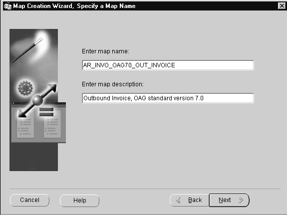
Specify a unique map name. This is the name assigned to the message map you are creating. It is also the name to be used when associating a message map to a Trading Partner.
Enter Map Name
Enter a unique map name. This name is stored as the map code in the map definition file.
In addition to being unique, the name should describe the intended use of the map for easy identification. The recommended naming convention is as follows:
-
Product mnemonic or user ID
-
Transaction subtype as entered in the Define Transactions form
-
XML standard and version used (for example, OAG, Rosettanet, iFX)
-
Inbound or outbound message
Examples of map names using the recommended naming convention are:
-
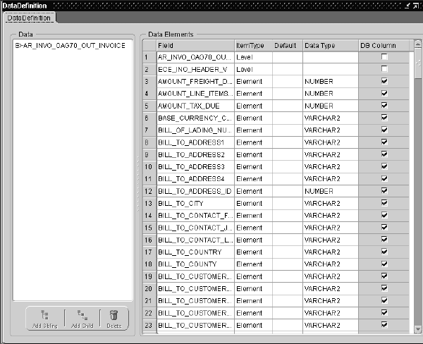
AR_INVO_OAG70_OUT_INVOICE
This map name is used for an Oracle Receivables outbound invoice message that uses the OAG standard, version 7.0 DTD.
-
USER_ACK_OAG70_IN
This name represents a user-developed map for an inbound acknowledgment message that uses the OAG standard, version 7.0 DTD.
Note: You can use the File > Properties menu option to change the Map Name and Map Description as necessary.
Enter Map Description
Enter a description for the map.
Note: You can use the File > Properties menu option to change the Map Name and Map Description as necessary.
Click Next to continue. The Wizard will display the Select/Create a Source Data Definition window.
Select/Create a Source/Target Data Definition
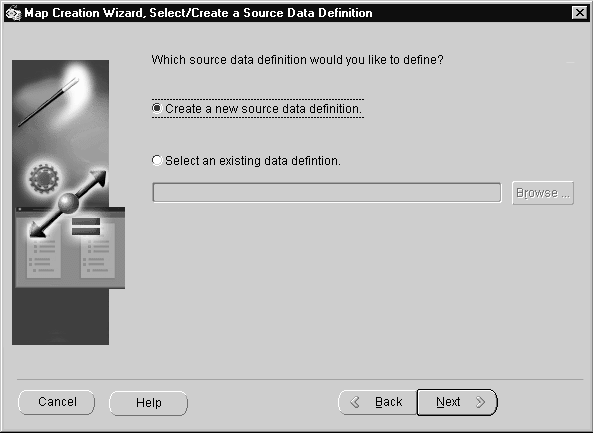
Select an existing data definition file or create a new data definition file.
Create a new source/target data definition
Select this option to create a new data definition. The Wizard will guide you through creating your new .XGD file.
Select an existing data definition
Existing definition files are stored on the file system as <filename>.XGD. Use the Browse button to view the available data definition files.
Click Next to continue
-
If you are defining your Source data definition and you selected...
-
Create a new source data definition, proceed to Specify Source/Target Data Definition Name and Type.
-
Select an existing Source data definition, repeat this step for your Target Data Definition.
-
-
If you are defining your Target data definition and you selected...
-
Create a new target data definition, proceed to Specify Source/Target Data Definition Name and Type.
-
Select an existing Target data definition, proceed to Map Creation Wizard Summary.
-
Specify Source/Target Data Definition Name and Type
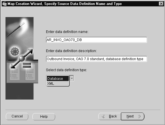
For a new data definition, enter a data definition name, description, and type.
Enter Data Definition Name
Enter a name that describes the contents of the data definition to allow easy identification.
This name is displayed in the Transaction Map window as the root node, if you select database as the data definition type. If you select XML as the data definition type, the DTD root element is displayed in the Transaction Map window as the root node instead of the data definition name entered here.
The recommended naming convention is as follows:
-
Product mnemonic or User ID
-
Transaction subtype as entered in the Define Transactions form
-
XML standard and version used (for example, OAG, Rosettanet, iFX)
-
Database or XML data definition type
Examples of data definition names using the recommended naming convention are:
-
AR_INVO_OAG70_DB
This name describes an Oracle Receivables-developed outbound invoice message that uses the OAG standard, version 7.0 DTD. This data definition is for the Database data definition type intended for use as the source data definition for an outbound message.
-
USER_ACK_OAG70_XML
This name describes a user-developed inbound acknowledgement message that uses the OAG standard, version 7.0 DTD. This data definition is for the XML data definition type intended for use as the source data definition for an inbound message.
Use the File > Properties menu option to change the Data Definition Name as necessary.
Enter Data Definition Description
Enter a description for the data definition.
Use the File > Properties menu option to change the Data Definition Description as necessary.
Select Data Definition Type
Select a data definition type from the following list of values:
-
Database
-
XML
Click Next to continue
The wizard steps to follow will vary based on the data definition type selected.
-
If you selected Database, proceed to Specify Source/Target Definition Database Information.
-
If you selected XML, proceed to Specify Source/Target XML File and Root Element.
Specify Source/Target Definition Database Information
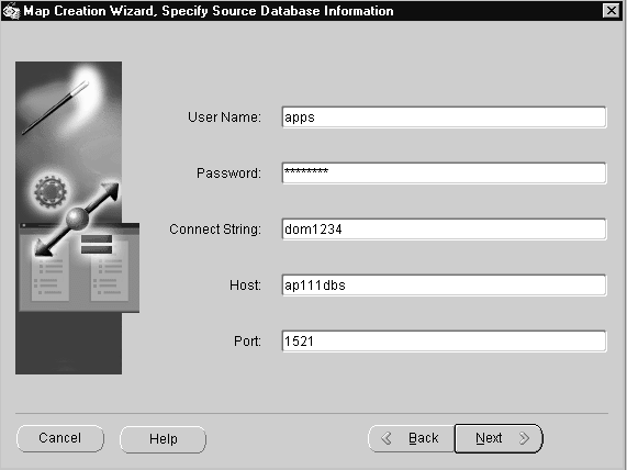
The default database access information is displayed from the Database tab of the File > Properties menu. Enter the password and make changes to the database access information if necessary.
Note: Changes made on this screen are not copied back to the Properties file. Entries on this screen are used for the current session only.
This step does not apply if the source/target is a DTD because database access is not required.
User Name
Enter the user name for the database schema to be accessed.
Password
Enter the password for your User Name.
Connect String
Enter the connect string for the database.
Host
Enter the host name for the database.
Port
The default value of "1521" is displayed. Enter another valid port value (if necessary) for the database to be accessed.
Click Next to continue. The Wizard will display the Select Source/Target Tables or Views window.
Select Source/Target Tables or Views
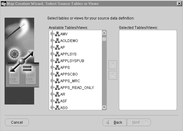
If you selected a Data Definition Type of Database, you will be prompted for the database schema, database views, and tables required by the message.
All application database views are defined in the APPS schema. The associated database tables are defined in the application-specific database schema. Access to application-specific database tables must be granted by defining a synonym in the APPS schema.
For applications with database views or tables shared across multiple hierarchical levels of the data model representing the business document, a database view or table alias is required for the second and each subsequent use of the view or table. This is necessary because this wizard step deletes a database view or table from the Available Tables/Views list once it has been selected.
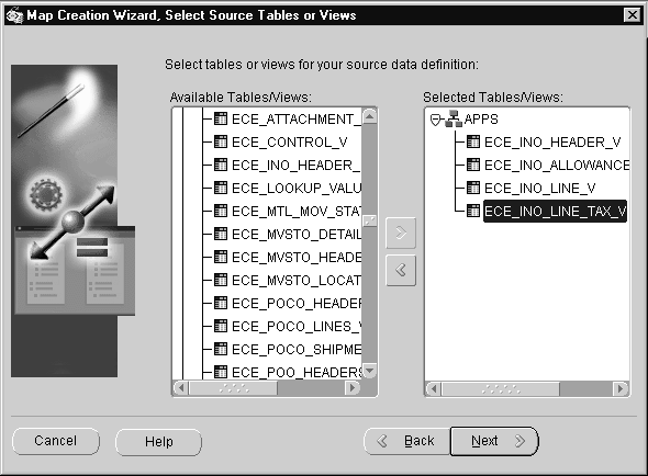
This step does not apply if the source/target is a DTD, because database information is not necessary.
Available Tables/Views
Expand the APPS database schema tree to view all the available database tables and views.
Selected Tables/Views
Select the desired database views and tables from the left window, click on the right shuttle to move the selected database view or table from Available Tables/Views to Selected Tables/Views. Continue this process until you have selected all the required database views and tables for each schema selected.
Once you have selected all the database views and tables required by the message, select any special XML Gateway database views you may have defined to support the specific requirements of the XML standard you are using.
For example, select the ECX_OAG_CONTROLAREA_TP_V (formerly ECX_OAG_CONTROLAREA_V) database view to map to the OAG CNTROLAREA data type.
Note: The ECX_OAG_CONTROLAREA_TP_V view is an upgraded version of the ECX_OAG_CONTROLAREA_V view. Oracle XML Gateway supports both versions of the database view.
The upgraded view includes new fields for USERNAME, SOURCE_TP_LOCATION_CODE, PARTY_ID, PARTY_SITE_ID, and PARTY_TYPE as well as changes to the following existing fields:
REFERENCE_ID is based on the system name, event name, and event key defined by the application business event. REFERENCE_ID was previously defaulted to "1" with recommendations to use the ECX_REFERENCE_ID sequence to get a unique number. The use of this field varies by message map.
You must add the ECX_EVENT_MESSAGE item attribute to your Workflow item type to have access to the event details.
CONFIRMATION is based on the setting defined for the Trading Partner and business document entered using the Define Trading Partners window. CONFIRMATION was previously defaulted to "0".
COMPONENT is based on the internal transaction type entered on the Define Transactions window for the business document. COMPONENT was previously based on the external transaction type.
TASK is based on the internal transaction subtype entered on the Define Transactions window for the business document. TASK was previously based on the external subtype.
TRANSACTION_SUBTYPE is based on the internal transaction subtype entered on the Define Transactions window. TRANSACTION_SUBTYPE was previously defaulted to the TRANSACTION_TYPE if no value was found in the database.
To deselect a selected database view or table, select the desired database view/table from the right window, click on the left shuttle button to move the selection from the Selected Tables/Views back to Available Tables/Views.
Click Next to continue. The Wizard will display the Select Source/Target Columns window.
Select Source/Target Columns
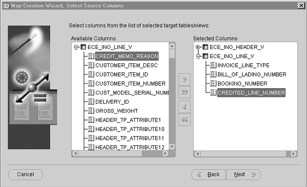
This window prompts you for the columns required from each of the database views or tables selected in the previous step.
This step does not apply if the source/target is a DTD because database information is not necessary.
Available Columns
Expand each of the database views and tables to view all the available database view and table columns.
Selected Columns
Select the desired database view or table column from the left window, click on the right shuttle button to move the selected database view or table column from Available Columns to Selected Columns. To move all the columns from a view or table, select the table or view and click the double right shuttle button to move all its columns from Available Columns to Selected Columns. Continue this process until all the required database view and table columns are selected.
You cannot proceed to the next wizard step until you have selected at least one column from each of the selected database views and tables. If necessary, return to the previous wizard step to deselect a database view or table and then resume the column selection process.
To deselect a selected database view or table column, highlight the desired column from the right window and click the left shuttle button to move the highlighted column from Selected Columns back to Available Columns. To deselect all the columns from a table or view, highlight the table or view name under Selected Columns and click the double left shuttle button to move all the columns back to the Available Columns area.
Click Next to continue. The Wizard will display the Specify Source/Target Levels window.
Specify Source/Target Levels
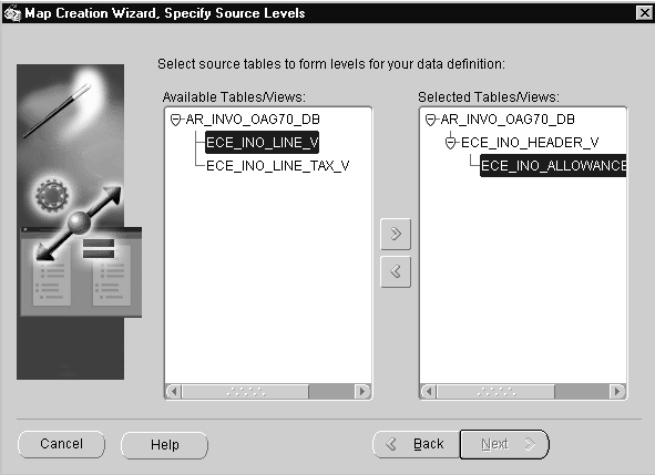
If you selected a Data Definition Type of Database, you will be prompted to identify the hierarchy of the source or target data definition. This step is necessary only if your source/target data definition contains more than one level.
A level represents a collection of data that repeats. For example, Purchase Order lines represent a level within a Purchase Order because there are multiple PO lines to a single PO.
The purpose of this step is to identify the parent and child relationships of each database view. The source hierarchy will be used to relate to the target hierarchy as part of the map creation process.
This step does not apply if the source/target is a DTD because database information is not necessary.
Available Tables/Views
The available database views and tables are displayed for your selection.
Selected Tables/Views
This window allows you to define the parent and child relationships of the selected database views and tables along with the special database views necessary to relate the database data model to the DTD data model.
Start by identifying the parent node. For OAG, the parent node is the ECX_OAG_CONTROLAREA_TP_V view (formerly ECX_OAG_CONTROLAREA_V). Related to the parent node are sibling or child nodes.
Note: The ECX_OAG_CONTROLAREA_TP_V view is an upgraded version of the ECX_OAG_CONTROLAREA_V view. Oracle XML Gateway supports both versions of the database view. For more information see the Note.
Sibling and child relationships are defined by first identifying the parent node in the Selected Tables/Views window (right). The database view or table you move from the the Available window to the Selected window will always be added as the last child of the parent node selected.
Therefore, to specify a sibling relationship to a specific node, select its parent node in the Selected Tables/Views column (right window). Next select the database view or table in the Available Tables/Views (left window) that you want to define as its sibling. Click on the right shuttle. The selected database view or table will be displayed as the last child of the parent node selected, or as a sibling to the desired node.
To specify a child relationship to a specific node, select the node in the Selected Tables/Views column (right window). Next select the database view or table in Available Tables/Views (left window) that you want to define as its child, and click on the right shuttle. The selected database view or table will be displayed as the last child of the selected parent node.
Continue this process until all available database views and tables have been moved to Selected Tables/Views.
This completes the data definition process.
Click Next to continue
If you have just finished your Source Data Definition, return to Select/Create a Source/Target Data Definition to define your Target Data Definition.
If you have just finished your Target Data Definition, proceed to Map Creation Wizard Summary.
Specify Source/Target XML File and Root Element
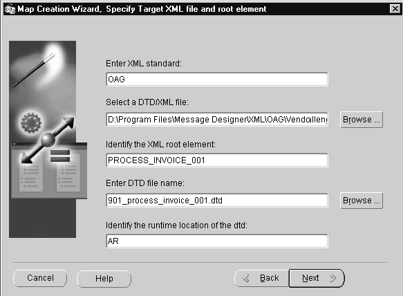
If you selected XML as the data definition type, you will be prompted for the XML information. You can use a DTD or a production XML message as the data definition.
XML Standard
Enter the XML standard used.
"OAG" (Open Application Group XML Standard) is the default.
Select a DTD/XML File
Select the DTD from the list of available DTDs presented when you click on the Browse button, or enter a specific DTD including the file path. The selected DTD and its file path are displayed.
To base the data definition on a production XML message, enter the file path and file name of the XML message.
The DTD or production XML message is used to create the definition tree for the Message Designer.
This step assumes that the required DTD and the associated external reference DTD files are available on the file system and are accessible by the Message Designer. For example, the OAG definition files are
-
oagis_domains.dtd
-
oagis_resources.dtd
-
oagis_fields.dtd
-
oagis_segments.dtd
Identify the XML Root Element
Enter the XML root element. Open the DTD or production XML message using a browser or XML editor to determine the root element name if you do not know it.
Note: Because the representation of root element varies by XML standard, this step is required to inform the Execution Engine where to begin reading the DTD.
Use the File > Properties menu option to change the Root Element as necessary.
Enter DTD File Name
If you entered a DTD above, the DTD file name will display automatically.
If you entered a production XML message above, click the Browse button to select the corresponding DTD from the list of available DTDs, or enter a specific DTD if available.
The DTD file name entered is used to validate a message to ensure that it is well-formed and valid before placing an outbound message on the outbound queue or processing a message dequeued from the inbound queue.
In addition, the primary DTD and its associated definition files must be loaded into the XML Gateway repository for access by the XML Gateway Execution Engine.
Note: Refer to How to Load/Delete Message Maps and DTDs for more details.
Use the File > Properties menu option to change the DTD File Name as necessary.
Identify the Runtime Location of a DTD
Enter the subdirectory name using the following naming convention:
<application code>/xml/<standard><standards version>
Examples:
ar/xml/oag62
ap/xml/oag70
Note: Do not use a period (.) when referencing a standards version.
The combination of the runtime DTD location and the DTD file name provides a unique identifier for the DTD required.
Use the File > Properties menu option to change the Runtime Location of a DTD as necessary.
Click Next to continue
If you have just finished your Source Data Definition, return to Select/Create a Source/Target Data Definition to define your Target Data Definition.
If you have just finished your Target Data Definition, proceed to Map Creation Wizard Summary.
Map Creation Wizard Summary
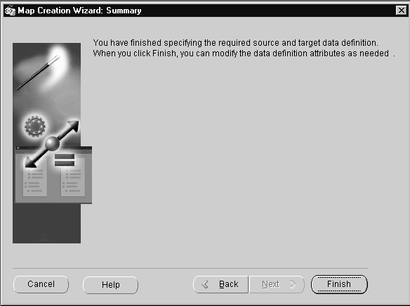
Click Finish to exit the Map Creation Wizard. If you wish to change any selections you have made in defining your map, use the Back button to return to the appropriate Wizard window.
Before proceeding to the level and element mapping process, the XML Gateway, in conjunction with the XML Parser, performs the following validations:
-
When the DOCTYPE tag is present in an XML message, verify that the DTD referenced is accurate.
-
Verify that the XML root element matches the DTD identified. When a production XML message is identified, verify that the root element and DTD identified match the production XML message.
-
Verify that external DTDs referenced by the primary DTD are available.
-
Check for circular DTD references. Process the first occurrence, truncate the remainder and warn user to manually add the necessary repeating occurrences.
Transaction Map Window
Upon exiting the Map Creation Wizard, the source and target definitions are presented in the Transaction Map window.
The Transaction Map window will also be presented if you select an existing map with a version number compatible with the version number of Message Designer.
The version number of the map (.xgm file) is stored in the <ECX_MAJOR_VERSION> and <ECX_MINOR_VERSION> tags. The Message Designer version number is available in the Help > About menu. Maps are compatible with Message Designer if the major version is the same and the minor version is the same or lower.
The Transaction Map window is divided into four tabs as follows:
-
Source Definition
-
Target Definition
-
Level Mapping
-
Element Mapping (this tab appears only after a Level has been mapped)
Source Definition
The source definition selected or created using the Map Creation Wizard is displayed in the Source Definition tab. You can extend the source definition to perform the following:
-
Provide default values
-
Enable code conversion
-
Create duplicate nodes or elements using the Add Sibling button
-
Add fields using the Add Child button
-
Define conditional node mapping rules for duplicate nodes or elements (if the source is a DTD)
Once the source data definition is complete, it can be saved for reuse in other message maps. Use the File > Save (Data Definition) menu option or the Toolbar equivalent. Use the File > Properties menu to change the default directory or data definition property values if necessary.
If you do not wish to save the source data definition as an entity independent of the message map, then continue with the mapping process and save the transaction map at the end of the Element Mapping process.
Source Definition Considerations
-
Refer to How to Map a Pass-Through Message, for guidelines related to developing a pass-through transaction.
A discontinuous node is a non-level node that follows a level and is a sibling of that level. It can be represented graphically as follows:
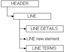
In this example, the levels LINE DETAILS and LINE TERMS are children of the level LINE, and are siblings of each other. Inserted between LINE DETAILS and LINE TERMS is a new element of the LINE node. The new element is a continuation of the LINE node that creates a break between LINE DETAILS and LINE TERMS.
The ideal placement of the new element is as the last element of the LINE node before the LINE DETAILS node. However, some standards bodies do not have the flexibility to restructure an existing DTD, or may not wish to for backwards compatibility reasons. Regardless of the reason, the condition exists, and XML Gateway supports it.
For data definitions based on the Oracle data model, use the Add Child or Add Sibling button in the Message Designer, Transaction Map window to define a discontinuous node. Any new node introduced on the source and distributed across multiple target levels (expanded) or consolidated into a single target level (collapsed) will be grouped with the parent node and mapped according to the target definition. The rules against level cross-over still apply.
For data definitions based on a DTD, use the Transaction Map window, Item Type column to explicitly identify the data levels. This exercise may create a discontinuous node, which is not a problem unless you define the invalid scenario described below. The only user extensions supported for OAG DTDs are in the USERAREA. If you modify the DTD (using the Add Child or Add Sibling buttons) outside of the USERAREA, a parsing error will be triggered.
Message Designer will allow you to define a discontinuous node anywhere in the source or target definition. You will not know until runtime if the definition is valid or not. Therefore you should avoid introducing a discontinuous node for a node which also contains a child node.
The following graphic illustrates an invalid definition:
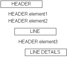
In the example above, HEADER.element3 is a continuation of the HEADER node. HEADER.element3 is also defined as a child of the LINE node. HEADER.element3 has a child node called LINE DETAILS. This is an invalid definition.
-
Refer to How to Implement the OAG Confirmation Business Object Document, for details on how to implement the optional confirmation message.
-
Refer to How to Implement Attachments in XML Messages for details on how to include attachments with your XML documents.
Source Definition Tab
Field
Field identifies the name of the element, document, or root. The names are based on the database column names or DTD element names.
The field name may be changed if necessary, however, consider what this change implies. Because the field is based on the database column name or a DTD element name, corresponding changes may be necessary in the Oracle E-Business Suite or the DTD. The only changes allowed to a DTD are to the USERAREA. Refer to How to Extend DTDs for details.
The first row is reserved for the Data Definition name (if the source is based on database views or tables) or root element name (if the source is a DTD).
Additional field names are displayed when sibling or child elements are added using the Add Sibling or Add Child buttons.
Item Type
Item type identifies the field as either a Level or an Element. Level represents the parent in a parent-child relationship. Element represents the child in a parent-child relationship.
The Item Type of the first row is defaulted to "Level". You cannot change this value.
If the source is based on database views or tables, the Item Type for the database view or table is defaulted to "Level". The Item Type for each database view or table column is defaulted to "Element".
If the source is based on a DTD or a production XML message, the default Item Type is "Element". DTDs do not support levels, therefore any levels must be explicitly defined by setting the Item Type to "Level".
Any node that represents a collection of data that repeats (for example, Purchase Order lines or shipment lines) represents a level. The Item Type for the node must be set to Level.
For the OAG standard, change the Item Type of the following to Level to support Level Mapping:
-
Root
-
CNTROLAREA
-
DATAAREA
Make the same change for all other DTD data types identified as data levels during the map analysis process.
The Item Type for a new sibling or child element is defaulted to "Element". Change the Item Type setting when appropriate.
Default
Enter a default value for the field as appropriate. This value is used in the outbound message or an inbound message if the incoming value is null.
If the default value is based on a condition, set the default using the Assign Variable Value action. See Assignments: Assign Variable Value .
If Item Type is "Level", this column is disabled.
Category
Enable the field for code conversion by entering a valid code category. Validation of code category is performed at runtime because the database used to define the map may not be the database where the transaction is executed. Refer to Seeded Code Categories for a list of seeded code categories.
Universal or standards-specific code conversion values are defined using the Define Code Conversion Values form. Trading Partner-specific code conversion values are defined using the Trading Partner Code Conversion form.
The execution engine will search for code conversion values in the following sequence:
-
Trading Partner
-
Standard-specific
-
Universal list
Use the Get Predefined Variable Value action to determine the status of the code conversion process for the source column enabled for code conversion.
See Get Predefined Variable Value for details regarding the code conversion return status and possible actions to take if the code conversion cross-reference value is not found.
Code conversion is applied before any Actions are applied. Consider the code conversion return status when you define Actions for the source column enabled for code conversion. Actions are applied to the code-converted value only when the code conversion process is successful.
If Item Type is Level, this column is disabled.
Data Type
Each field is defined with a data type. The data types supported by the XML Gateway Execution Engine are VARCHAR2, DATE, NUMBER, CHAR, and CLOB.
The CLOB data type is used to support large objects up to 4 GB in size. The CLOB is displayed between CDATA tags to escape parsing.
If the source is based on database views or tables, the data types are defaulted to the data types defined for the view or table columns.
If the source is based on a DTD or a production XML message, the data type is defaulted to VARCHAR2.
Important: It is not necessary to change the DTD element's data type until XML schemas are supported by the XML standards bodies which will make data types more meaningful.
The Data Type for a new sibling or child element is defaulted to VARCHAR2. Change the data type if necessary.
If the Item Type is Level, the Data Type column is disabled.
DB Column
The DB Column is available only when the source is based on database views or tables.
A check mark indicates the column is defined in the Oracle E-Business Suite data model. This setting informs the XML Gateway Execution Engine whether to validate the element against the Oracle E-Business Suite data model or not.
If Item Type is Level, the DB Column is disabled.
Node Type
Node Type is available only when the source is a DTD. The default is the DTD setting.
The valid values are Element or Attribute. Elements contain the business data. Attributes contain qualifiers for the business data to indicate its intended meaning.
The Node Type for a new sibling or child element is defaulted to Element. Change the Node Type setting where appropriate.
If Item Type is Level, this column is disabled.
Add Sibling (button)
The Add Sibling button allows you to add new fields required to complete the map. This feature is also used to create duplicate DTD nodes such as PARTNER.
When the source is based on a DTD or production XML message, and you are adding a sibling between two attributes, set the Node Type for the new field to "Attribute". The default Node Type of "Element" will cause a parser violation.
Important: You cannot add a sibling to the root node.
Refer to How to Extend DTDs for details on how to extend a DTD. Included are the naming conventions that must be followed for the XML Parser to recognize the DTD extensions.
Add Child (button)
The Add Child button adds child elements to an existing sibling or child. In addition, Add Child can be used to define an attribute for the root element if the source or target is a DTD.
This function may be used if the source is database views or tables or a DTD.
If Node Type is "Attribute", the Add Child button is disabled. You cannot define an attribute for an attribute.
Note: Refer to How to Extend DTDs for details on how to extend a DTD. Included are the naming conventions that must be followed for the XML Parser to recognize the DTD extensions.
Delete (button)
The Delete button allows you to delete any sibling or child element that has not been mapped.
If a sibling or child has child elements associated with it, a warning is displayed before the delete occurs.
Important: If you are deleting any DTD extensions, be sure to remove the DTD extensions from the corresponding extension file created for the application or user. The extra information will not cause a parser violation, but it is a good practice to ensure the extension files match the message maps. Refer to How to Extend DTDs for the details.
Conditional Node Mapping Window
Condition.../Delete Condition
If the source definition is based on a DTD with duplicate nodes or elements of the same name, use Conditional Node Mapping to ensure that the source-to-target mappings are performed correctly. This is required because the sequence of duplicate nodes and elements is not fixed.
Examples of duplicate nodes that occur frequently in a DTD are DATETIME, AMOUNT, OPERAMT, and QUANTITY. Using a purchase order as an example, the first DATETIME occurrence is for the Order Date and the second occurrence is for the Promise Date.
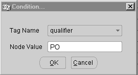
Conditional node mapping allows you to define the relationship of the source node to the target node based on the value of key elements. The key elements are identified by the Tag Name and Node Value combination. For the purchase order example above, the Tag Name is "qualifier" and the Node Value is "PO" for the first DATETIME occurrence representing the order date. The Tag Name for the second DATETIME occurrence is also "qualifier" with a Node Value of "PROMDELV" for promise date.
To define the key values, select the source DTD node and click the right mouse button to invoke the Conditional Node Mapping window. You will be prompted for the following:
| Variable | Description |
|---|---|
| Tag Name | Select Tag Name from the list of values. Using the above example, this is the "qualifier" attribute associated with the DATETIME segment that uniquely identifies the node and its intended meaning. |
| Node Value | Enter the node value. Using the above example, this is either "PO" or "PROMDELV". |
Repeat this process for each of the duplicate nodes and elements. Message Designer supports one condition per node or element.
To delete the Conditional Node Mapping instruction for a node, select the node and click the right mouse button to invoke the Delete Condition function.
Conditional node mapping is applicable to source data definitions that are based on a DTD or a production XML message. It does not apply when the source data definitions are based on database views or tables.
Transaction Map - Target Definition
The target definition selected or created using the Map Creation Wizard is displayed in the Target Definition Tab. The target definition can be extended to perform the following:
-
Provide default values
-
Create duplicate nodes and elements using the Add Sibling button
-
Add fields using the Add Child button
-
Delete unused and unmapped DTD elements to prevent parser violations
Once the target data definition is complete, it can be saved for reuse in other message maps. Use the File > Save (Data Definition) menu option or the toolbar equivalent. Use the File > Properties menu option to change the default directory or data definition property values if necessary.
If you do not wish to save the target data definition as an entity independent of the message map, then continue with the mapping process and save the transaction map at the end of the Element Mapping process.
Target Definition Considerations
-
Refer to How to Map a Pass-Through Message, for guidelines related to developing a pass-through transaction.
-
Refer to How to Map to an API for guidelines for mapping an inbound message to an Application API (as opposed to mapping to Application Open Interface tables).
-
For DTD elements defined using "|" as the occurrence indicator, make sure you select one element from the choice list and delete the unused elements. The parser will validate that only one element is used.
-
Delete optional DTD data types and elements that are not used and therefore not mapped. If not deleted, these elements will appear as empty tags in the resulting message.
-
If you decide not to delete DTD data types and elements that are not used and not mapped, default the data type or element attribute to "OTHER". The parser requires the attribute even though the data type or element is optional.
-
Refer to How to Implement Attachments in XML Messages for details on how to include attachments with your XML documents.
A discontinuous node is a non-level node that follows a level and is a sibling of that level. It can be represented graphically as follows:
In this example, the levels LINE DETAILS and LINE TERMS are children of the level LINE, and are siblings of each other. Inserted between LINE DETAILS and LINE TERMS is a new element of the LINE node. The new element is a continuation of the LINE node that creates a break between LINE DETAILS and LINE TERMS.
The ideal placement of the new element is as the last element of the LINE node before the LINE DETAILS node. However, some standards bodies do not have the flexibility to restructure an existing DTD, or may not wish to for backwards compatibility reasons. Regardless of the reason, the condition exists, and XML Gateway supports it.
For data definitions based on the Oracle data model, use the Add Child or Add Sibling button in the Message Designer, Transaction Map window to define a discontinuous node. Any new node introduced on the source and distributed across multiple target levels (expanded) or consolidated into a single target level (collapsed) will be grouped with the parent node and mapped according to the target definition. The rules against level cross-over still apply.
For data definitions based on a DTD, use the Transaction Map window, Item Type column to explicitly identify the data levels. This exercise may create a discontinuous node, which is not a problem unless you define the invalid scenario described below. The only user extensions supported for OAG DTDs are in the USERAREA. If you modify the DTD (using the Add Child or Add Sibling buttons) outside of the USERAREA, a parsing error will be triggered.
Message Designer will allow you to define a discontinuous node anywhere in the source or target definition. You will not know until runtime if the definition is valid or not. Therefore you should avoid introducing a discontinuous node for a node which also contains a child node.
The following graphic illustrates an invalid definition:
In the example above, HEADER.element3 is a continuation of the HEADER node. HEADER.element3 is also defined as a child of the LINE node. HEADER.element3 has a child node called LINE DETAILS. This is an invalid definition.
Target Definition Tab
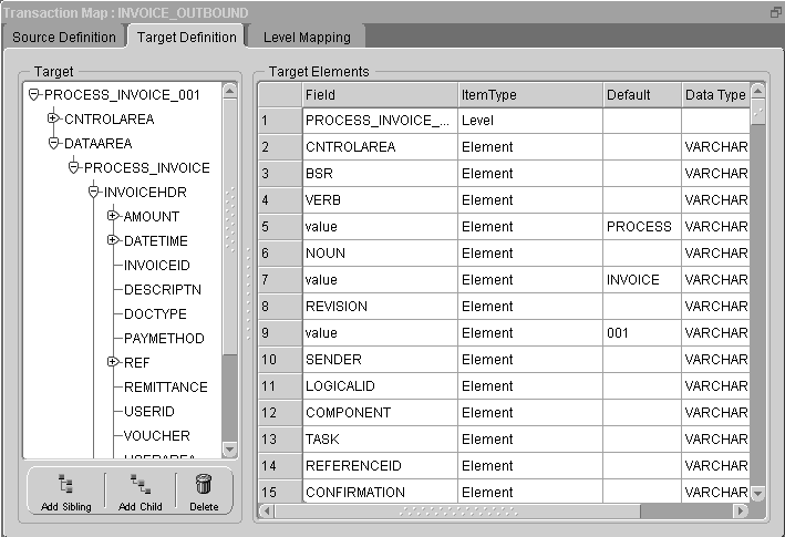
Field
Field identifies the name of the element, document, or root. The names are based on the Application Open Interface table column names or DTD element names.
The field name can be changed if necessary, however, consider what this change implies. Because the field is based on the database column name or a DTD element name, corresponding changes may be necessary in Oracle E-Business Suite or the DTD. The only changes allowed to a DTD are to the USERAREA. Refer to How to Extend DTDs for details.
The first row is reserved for the Data Definition name (if target is based on Application Open Interface) or DTD root element name (if target is a DTD).
Additional field names are displayed when sibling or child elements are added using the Add Sibling or Add Child buttons.
Item Type
Item type identifies the field as either a Level or an Element. Level represents the parent in a parent-child relationship. Element represents the child in a parent-child relationship.
The Item Type of the first row is defaulted to Level. The default value cannot be changed.
If the target is based on Application Open Interface tables, the Item Type for the tables is defaulted to "Level". The Item Type for the columns is defaulted to "Element".
If the target is based on a DTD or a production XML message, the default Item Type is "Element". DTDs do not support levels and therefore the levels must be explicitly defined by setting the Item Type to "Level".
Any node that represents a collection of data that repeats (for example, PO lines or shipment lines) represents a level. The Item Type for the node must be set to "Level".
For the OAG standard, change the Item Type of the following to "Level" to support Level Mapping:
-
Root
-
CNTROLAREA
-
DATAAREA
Make the same change for all other DTD data types identified as data levels during the map analysis process.
The Item Type for a new sibling or child element is defaulted to "Element". Change the Item Type setting where appropriate.
Default
Enter a default value for the field as appropriate. This value is used in the outbound message. The default value will be used in an inbound message if the incoming value is null.
If the target is a DTD, use the Default column to set the DTD attribute values. The values will be displayed with the corresponding attribute tags when the message is created.
If the default value is based on a condition, set the default using the Assign Variable Value action. See Assignments: Assign Variable Value.
If Item Type is Level, this column is disabled.
Data Type
Each field is defined with a data type. The data types supported by the XML Gateway Execution Engine are VARCHAR2, DATE, NUMBER, CHAR, and CLOB.
The CLOB data type is used to support large objects up to 4 GB in size. The CLOB is displayed between CDATA tags to escape parsing.
If the target is based on Application Open Interface tables, the data type is defaulted to the data type defined for the database column.
If the target is based on a DTD or a production XML message, the data type is defaulted to VARCHAR2.
Important: It is not necessary to change the DTD element's data type until XML schemas are supported by the XML standards bodies which will make data types more meaningful.
The Data Type for a new sibling or child element is defaulted to VARCHAR2. Change the data type if necessary.
If Item Type is Level, the Data Type column is disabled.
DB Column
DB Column is available only when the target is based on Application Open Interface tables.
A check mark indicates the column is defined in the Oracle E-Business Suite data model. This setting informs the XML Gateway Execution Engine whether to validate the element against the Oracle E-Business Suite data model or not.
If the Item Type is Level, the DB Column is disabled.
Node Type
Node Type is available only when the target is a DTD. The default is the DTD setting.
The valid values are Element or Attribute. Elements contain the business data. Attributes contain qualifiers for the business data to indicate the intended meaning of the data.
The Node Type for a new sibling or child element is defaulted to "Element". Change the Node Type setting if appropriate.
If Item Type is Level, the Node Type column is disabled.
Add Sibling (button)
The Add Sibling button allows you to add new fields required to complete the map. This feature is also used to create duplicate DTD nodes such as PARTNER.
The same can be done if the target is Application Open Interface tables.
When the target is based on a DTD or production XML message, and you are adding a sibling between two attributes, set the Node Type for the new field to "Attribute". The default Node Type of "Element" will cause a parser violation.
Important: You cannot add a sibling to the root node.
Refer to How to Extend DTDs for details on how to extend a DTD. Included are the naming conventions that must be followed for the XML Parser to recognize the DTD extensions.
Add Child (button)
The Add Child button adds child elements to an existing sibling or child. In addition, Add Child can be used to define an attribute for the root element if the source or target is a DTD.
This function can be used if the target is Application Open Interface tables or a DTD.
If Node Type is "Attribute", the Add Child button is disabled. You cannot define an attribute for an attribute.
Note: Refer to How to Extend DTDs for details on how to extend a DTD. Included are the naming conventions that must be followed for the XML Parser to recognize the DTD extensions.
Delete (button)
The Delete button deletes any sibling or child element that has not been mapped.
If a sibling or child has child elements associated with it, a warning is displayed before the delete occurs.
Important: If you are deleting any DTD extensions, be sure to remove the DTD extensions from the corresponding extension file created for the application or user. The extra information will not cause a parser violation, but it is a good practice to ensure the extension files match the message maps. Refer to How to Extend DTDs for the details.
Transaction Map - Level Mapping Tab
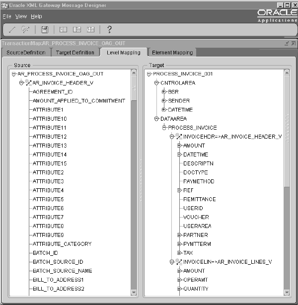
In the Level Mapping tab, the source definition is presented in the left window and the target definition in the right window. Use the Level Mapping tab to relate the source hierarchy to the target hierarchy. All entities defined as a level are displayed in bold.
Select the source level and drag it to the desired target level. The source level name and the mapped icon will appear to the right of the target level name indicating the level is mapped.
If this does not occur as described, you have not set the DTD entity Item Type to "Level". Return to the Source or Target Definition tab and set the Item Type accordingly, then resume with Level Mapping.
To unmap a mapped level, simply select the mapped level on the target window and drag it back to the source level.
Level Mapping Guidelines for OAG DTDs
-
For the outbound messages using the OAG standard, map the ECX_OAG_CONTROLAREA_TP_V view (formerly ECX_OAG_CONTROLAREA_V) to the DTD CNTROLAREA data type. This step is not required for inbound messages because the content of the DTD CNTROLAREA is not stored in the Oracle E-Business Suite.
Note: The ECX_OAG_CONTROLAREA_TP_V view is an upgraded version of the ECX_OAG_CONTROLAREA_V view. Oracle XML Gateway supports both versions of the database view. For a detailed description of the differences, see the Note, presented earlier in this chapter.
-
If you anticipate multiple documents in a message, map the database header view to the OAG document header data type. If you anticipate a single document in a message, map the database header view to the OAG DATAAREA data type.
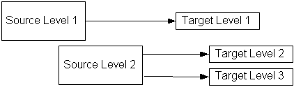
Level Mapping Guidelines to Collapse Levels
Multiple source levels can be mapped to the same target level. This is commonly referred to as collapsing levels. For example, if your source is 3 levels and your target is 2 levels you can collapse the levels as shown in the following figure:
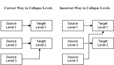
In the correct example above, there are three source levels and two target levels. Source Level 1 is mapped to Target Level 1. Source Levels 2 and 3 are mapped to Target Level 2. The result of collapsing levels is that the data in Source Levels 2 and 3 are consolidated and mapped to Target Level 2. If there are two rows in Source Level 2 and three rows in Source Level 3, a total of six rows will be created in Target Level 2.
In the example showing the incorrect collapsing of levels, Source Level 3 is mapped over Target Level 2 to Target Level 1.
Another option shown below is to relate Source Levels 1 and 2 to Target Level 1 and relate Source Level 3 to Target Level 2. (Do not map Source Levels 1 and 3 to Target Level 1, crossing over Target Level 2.)
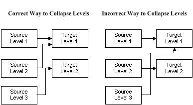
Whichever option you choose, consider what it means to promote lower level detail data to a higher level. The lower level data may need to be aggregated to be meaningful at the higher level.
Level Mapping Guidelines to Expand Levels
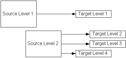
One source level can be mapped to multiple target levels. This is commonly referred to as expanding levels. For example, if your source is two levels and your target is three levels you can expand the levels as shown in the following figure:
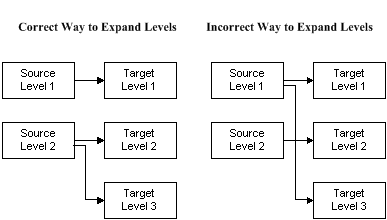
In the correct example above, Source Level 1 is mapped to Target Level 1 and Source Level 2 is mapped to Target Levels 2 and 3. The result of expanding levels is that the data in Source Level 2 is distributed and mapped to Target Levels 2 and 3. If there are two rows in Source Level 2, two rows will be created in Target Level 2 and Target Level 3.
In the example showing the incorrect expansion of levels, Source Level 1 is mapped to Target Level 1 and Target Level 3, crossing over Target Level 2.
Another option, shown below, is to distribute Source Level 1 to Target Levels 1 and 2 and map Source Level 2 to Target Level 3. (Do not map Source Level 1 to Target Levels 1 and 3, crossing over Target Level 2.)
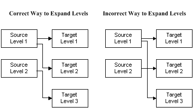
Whichever option you choose, consider what it means to demote data from a higher level to a lower level of detail. The higher level data may need to be deaggregated to be meaningful at the lower level.
Level Expansion for Discontinuous Nodes
Level expansion is supported if the target expanded levels are all siblings of each other or if they are all children of the previous node.
Valid Level Expansion
In the example above, Target Level 2 and Target Level 3 are siblings to each other and children of Target Level 1.
Invalid Level Expansion
In the example of invalid level expansion above, Target Level 2 and Target Level 3 are siblings to each other and children of Target Level 1. Target Level 4 is a sibling of Target Level 1, with no relationship to Target Levels 2 and 3.
See Discontinuous Nodes for more information on discontinuous nodes.
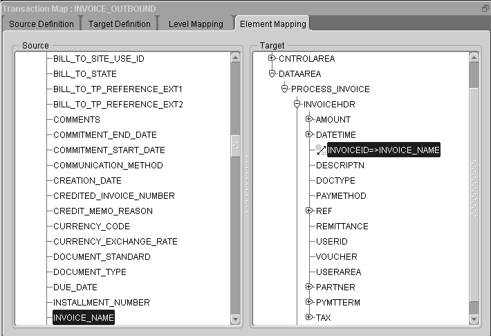
Transaction Map - Element Mapping
If the Element Mapping tab is not available, it is an indication that you have not completed at least one level mapping in the Level Mapping process.
Once the Level Mapping process is complete, the source definition is presented on the left window and the target definition is presented on the right window. The source and target hierarchies defined in the Level Mapping tab are displayed in bold font. Use the Element Mapping tab to create the message map.
Select the source element and drag it to the target element. Pay special attention to any predefined node conditions (such as Conditional Node Mapping) to ensure that duplicate nodes are mapped to the correct target entities. The source element name and mapped icon will appear next to the target element name indicating the element is mapped.
To unmap a mapped element, select the mapped element on the target window and drag it back to the source element.
Element Mapping Guidelines
-
Do not map a lower level element to a higher level element. The lower level element values are not available until the header level elements are completely processed.
-
A higher level element can be mapped to a lower level element. However, you may need to manipulate the higher level element value to make it meaningful in the context of a detail level element.
For example, if the the header level element is invoice total and the line level element is invoice line total, the header invoice total must be distributed across the invoice lines based on the line quantity for it to be meaningful in the context of invoice lines.
-
One source element can be mapped to multiple target elements.
-
Review the source elements containing Conditional Node Mapping instructions. Map the source element to the target element associated with the condition.
For the outbound messages (where the source is the database and the target is a DTD) using the OAG standard, map the ECX_OAG_CONTROLAREA_TP_V view (formerly ECX_OAG_CONTROLAREA_V) columns to the DTD CNTROLAREA data type elements. This step is not required for inbound messages (where the source is a DTD and the target is the database) because the content of the DTD CNTROLAREA is not stored in the Oracle E-Business Suite.
Note: The ECX_OAG_CONTROLAREA_TP_V view is an upgraded version of the ECX_OAG_CONTROLAREA_V view. Oracle XML Gateway supports both versions of the database view. For a detailed description of the differences, see the Note presented earlier in this chapter.
The view column names are similar to the DTD CNTROLAREA data type element names, so this is one-to-one mapping. Add the following required Actions to complete the map:
-
Use the Convert to OAG DATETIME action to convert the Oracle date to the CNTROLAREA DATETIME element.
-
Use the Append Where Clause action to bind the transaction type and transaction subtype to the ECX_OAG_CONTROLAREA_V view. Or if you are using the ECX_OAG_CONTROLAREA_TP_V view, use the Append Where Clause to bind the transaction type, transaction subtype, party ID, party site ID, and party type to the view.
Note: The ECX_OAG_CONTROLAREA_TP_V view is an upgraded version of the ECX_OAG_CONTROLAREA_V view. Oracle XML Gateway supports both versions of the database view. For a detailed description of the differences, see the Note, presented earlier in this chapter.
Use the Define Transactions form to define the transaction and transaction subtype that represent the Oracle name for the message. Associated with the internal name for the message are the external type and subtype that represent the message name in the XML standard of choice.
For OAG, the external subtype corresponds to the BSR VERB and the external type corresponds to the BSR NOUN. The names entered on the Define Transactions form are stored in the database and accessed by the ECX_OAG_CONTROLAREA_TP_V view. The values are displayed in the Message Designer as default values for the BSR VERB and BSR NOUN elements.
-
Refer to the Define Transactions Form for the details and observe the recommended naming conventions.
Element Mapping Icons
Message Designer uses an icon group to help you determine the status of a map at a glance. The components of the icon group are as follows:
![]()
Mapped Element icon.
![]()
Action Defined icon.
![]()
Code Conversion Enabled icon.
The components will be displayed as on or off (grayed out) within the group icon to indicate if the element is mapped, has an action defined, and/or is enabled for code conversion.
Element Mapping and Actions
As part of the element mapping process, Actions for data transformation and process control can be defined.
The following three sections are available for your reference. First time users should read all three sections. Experienced users should use the Map Action Editor section and reference the action type of interest.
At the completion of the element mapping process, use the File > Save (Transaction Map) menu option or the Save icon to save the map onto the file system. The name of the map (.xgm) file should be the same as the map name for easy reference. Follow the map naming conventions as follows:
-
Product mnemonic or user ID
-
Transaction subtype as entered in the Define Transactions form
-
XML standard and version used (such as OAG, Rosettanet, iFX)
-
Outbound or inbound message
Given a map name of:
AR_INVO_OAG70_OUT
the map file name is:
AR_INVO_OAG70_OUT.xgm
Use the File > Properties menu option to change the default directory or map name if necessary.
The transaction map and the associated DTDs are now ready to load into the XML Gateway repository. The message maps will be used by the XML Gateway Execution Engine to create or to consume XML messages.
Refer to How to Load/Delete Message Maps and DTDs for details on loading a message map created by the Message Designer and its associated DTDs into the XML Gateway repository.
Transaction Map - Actions
As part of the element mapping process, Actions for data transformation or process control can be defined.
Actions are similar to prebuilt functions in that they may be called to perform a specific activity.
Oracle XML Gateway supports actions for data transformation involving math functions, string manipulation, and data conversion between Oracle's data format and OAG's data format.
Oracle XML Gateway supports a set of predefined actions for process control. This includes user-defined procedure and function calls to extend the integration with the Oracle E-Business Suite. Other common process control actions allow you to inquire on the status of a transaction and to manage the process flow based on the status. For serious errors, the transaction can be aborted with error messages returned to the sender via an Oracle Workflow process.
The actions supported by Oracle XML Gateway are listed in Appendix C.
Source or Target Action
Most Actions are defined on the target side of the Element Map with the exception of the Append Where Clause action type, which is defined on the source side of the Element Map if the source is based on database views or tables.
See Map Action Editor - Append Where Clause for a detailed description of this action and how to define it.
Action Levels
An Action may be defined for any of the following entities:
-
Element
An element is the smallest unit of a message. An action defined at the element level is applied to that element only.
-
Document
A document is a collection of elements representing a business document. An action defined at the document level is applied to the document.
-
Root
A root represents a collection of documents. An action defined at the root level is applied to all documents contained by the root.
Some actions are designed to be applied to the element only, while others are intended for the document only.
XML Gateway Execution Engine Processing Sequence
The processing sequence of a three-level document by the XML Gateway Execution Engine is described in the following table.
Refer to Pre Process, In Process, and Post Process Tabs, for a description of process stages.
| Level | Stage |
|---|---|
| Root | Preprocess |
| Root | In-Process |
| Header | Preprocess |
| Header | In-Process |
| Header | Postprocess |
| Line | Preprocess |
| Line | In-Process |
| Line | Postprocess |
| Line Detail | Preprocess |
| Line Detail | In-Process |
| Line Detail | Postprocess |
| Root | Postprocess |
Given the processing sequence described above, header data is processed before line data and line data is processed before detail data. Any upper level data element that has a dependency on lower level data elements (for example, sum of invoice lines) must be processed using an API call at the upper level. Once the upper level data is processed, it cannot be updated, although it can always be accessed.
Map Action Editor
How to Invoke the Map Action Editor
In the Element Mapping tab, select the entity (element, document, root) and click the right mouse button to invoke the Map Action Editor pop-up window. The prompts presented by the Map Action Editor will vary based on the Action type selected.
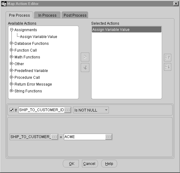
Overview
The Map Action Editor has the following common components:
-
Pre Process, In Process, Post Process Tabs
-
Available Actions
-
Selected Actions
-
Optional Conditional Expression
-
Result Variable
-
Action Operands - Element Window
Pre Process, In Process and Post Process Tabs
An Action can be applied at any of the following stages of message creation or consumption:
-
Pre Process
A preprocess action is executed before the message is created or consumed.
The Create Global Variable action is an example of a preprocess action. The variable must be defined before you can use it.
-
In Process
An in-process action is executed during message creation or consumption.
The Math and String Functions are examples of in-process actions used to perform a computation or to manipulate a value.
-
Post Process
A postprocess action is executed after the message is created or consumed.
The Insert into Database Table action is an example of a postprocess action. The row cannot be inserted into the database until all the data for the row has been processed.
Select the appropriate Map Action Editor Window Tab for the map entity (element, document, root) selected.
Available Actions
The available action categories for the selected process stage and selected map entity are displayed. Expand each category to view all the available action types.
The following table summarizes all action types sorted by Action Level and Action Stage. A "Y" indicates the action type is available for the Action Level and Action Stage combination. An "N" indicates the action type is not available for the Action Level and Action Stage combination.
| Action Category & Description | Element In Process | Document Pre Process | Document In Process | Document Post Process | Root Pre Process | Root In & Post Process |
|---|---|---|---|---|---|---|
| Assignment: Assign variable value | Y | Y | Y | Y | N | Y |
| Assignment: Create global variable | N | N | N | N | Y | N |
| Database Function: Assign next sequence value | Y | Y | Y | Y | N | Y |
| Database Function: Append where clause | N | DB Source | N | N | N | N |
| Database Function: Insert into database table | N | N | N | Y | N | N |
| Derivations | Y | N | N | N | N | N |
| Function Call | Y | Y | Y | Y | N | Y |
| Math Functions | Y | Y | Y | Y | N | Y |
| OAG Standard Conversions | Y | N | N | N | N | N |
| Other: Exit Program | Y | Y | Y | Y | N | Y |
| Predefined Variable | Y | Y | Y | Y | N | Y |
| Procedure Call | Y | Y | Y | Y | N | Y |
| Return Error Message | Y | Y | Y | Y | N | Y |
| String Functions | Y | Y | Y | Y | N | Y |
| XSLT Transformation | N | N | N | N | N | Y(Post) |
Selected Actions
To move an action type from Available Actions to Selected Actions, select the desired action type and click the shuttle button.
To deselect a selected action type, select the desired action type and click the shuttle button to move the selected action type from Selected Actions back to Available Actions.
Up and Down Arrows for the Selected Actions Window
A given entity (element, document, root) may have one or more Actions defined for it. The XML Gateway Execution Engine processes the Actions in the sequence defined, from the beginning of the list proceeding downward to the last action type on the list. Use the up and down arrows within the Selected Actions Window to change the sequence of the Actions defined for a given entity. Use the left shuttle button to deselect a Selected Action if necessary.
Optional Condition Expression: If <Operand 1><Operator><Operand 2>
Each Action may be defined as a conditional action (except the Append Where Clause and Create Global Variable). The condition is expressed as two operands. An operand may be a variable (source, target, or global variable) whose value is determined at runtime, or a literal value.
For each condition operand, click on the (...) icon to the right of the operand field to invoke the Element window. The Element window allows you to select a variable or provide a literal value.
Refer to Action Operands - Element Window for details regarding the Element window.
The operators supported by Oracle XML Gateway are listed in the following table:
| Operator | Description |
|---|---|
| = | Equal |
| != | Not Equal |
| > | Greater Than |
| < | Less Than |
| >= | Greater Than or Equal To |
| <= | Less Than or Equal To |
| Is NULL | Null |
| Is NOT NULL | Not Null |
Enter the two operands and select the operator if a condition expression is required.
Compound conditions can be defined by comparing two operands and storing the result in a variable (source, target, or global). You then compare the value in the variable with the next condition operand.
Result Variable
Some Actions have result variables defined and some do not. Those that do not have a result variable defined will use one of the action operands as the result variable.
The result variable is the left-most field of the action operand. The only exception occurs in the Convert To actions where the result variable is the right-most field. Per user interface standards, the result variable field is greyed, but is enabled for data entry.
For element-level Actions, the selected source or target variable is displayed as the default result variable. You can change the variable name as necessary.
For document-level or root-level actions, the result variable is blank. Click on the (...) icon to invoke the Element window. Select the source, target, or global variable as the result variable. The value of the result variable is determined at runtime.
The result variable cannot be a literal value.
Refer to Action Operands - Element Window for details regarding the Element window.
Action Operands - Element Window
An Action may or may not have operands associated with it.
For Actions that do have operands associated with them, the number of operands varies by action type. Click on the (...) icon to the right of the operand field to invoke the Element window.
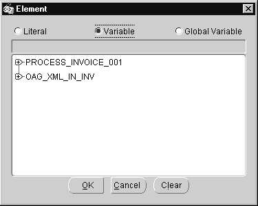
The Element window allows you to select a variable or provide a literal value. The Element window is presented in four parts as follows:
-
Radio button for Literal, Variable, or Global Variable
-
Operands displayed in gray indicate literal values are not allowed
-
Field for literal value (available only when Literal radio button is selected)
-
Window display for source and target variables
The default radio button setting is Variable. You can change the default by selecting a Literal (if available for the action type selected), or Global Variable (if defined).
The Literal radio button is enabled only if a literal value is applicable for the action type selected and the Element Window was not invoked from a Result Variable. Enter the literal value and click OK.
When the Variable radio button is enabled, you are presented with the source and target variables. Select the source or target variable name and click OK. The value for the selected variable is determined at runtime.
The Global Variable radio button is enabled only if global variables are defined for the message map. Select the Global Variable from the list of values and click OK. The value for the selected global variable is determined at runtime.
Map Action Editor - Assignments: Assign Variable Value
The Assign Variable Value action assigns a value to the result variable identified. The value may be based on another variable (source, target, or global variable) or a literal value.
If you are assigning a literal value as a default value to be applied universally (without a condition expression), you have the option to set the default value in the Transaction Map form using the Source or Target Definition tab.
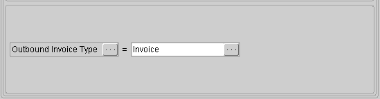
See Map Action Editor - Overview for details on the common components of the window.
Result Variable
Select the source, target, or global variable to store the assigned value.
Action Operands
Select the variable (source, target, or global variable) or enter the literal value to assign to the result variable.
Map Action Editor - Assignments: Create Global Variable
The Create Global Variable action allows you to define a variable available to both the source and target. A default value may be assigned to the variable or the variable may get its value from the Assign Variable Value action.
Once a global variable is defined, it is included in the Element window Global Variable Name list of values.
Note: The following are reserved names for global variables:
-
TRANSACTION_TYPE
-
TRANSACTION_SUBTYPE
-
DOCUMENT_ID
-
TP_SITE_ID (also known as PARTY_SITE_ID)
-
TP_ID (also known as PARTY_ID)
-
TP_TYPE (also known as PARTY_TYPE)
-
PARAMETER1, PARAMETER2, PARAMETER3, PARAMETER4, and PARAMETER5
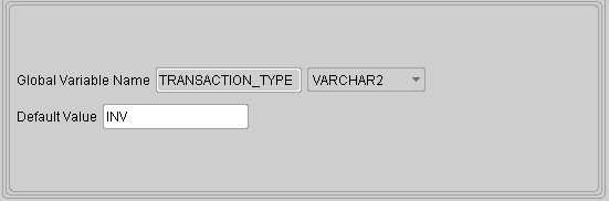
See Map Action Editor - Overview for details on the common components of the window.
The Optional Conditional Expression is not available for the Create Global Variable action because the action is a preprocess action and therefore data is not available yet.
Global Variable Name
Enter a global variable name and select the data type for the variable. The valid data types supported by the XML Gateway Execution Engine are VARCHAR2, NUMBER, DATE, and CHAR.
Important: Define a unique and meaningful name that does not contain a reserved word and is not a predefined variable. Once the variable name is defined and stored for the map, it cannot be changed.
However, if necessary, you can delete the Create Global Variable action containing the incorrect variable name and then add a new action containing the correct name.
Note: The CLOB data type defined to support large objects (up to 4GB) is supported by the XML Gateway execution engine, but not by the Create Global Variable action.
Default Value
Enter a default value if applicable.
Map Action Editor - Database Functions: Assign Next Sequence Value
Oracle E-Business Suite defines database sequences to maintain counters for document numbers such as PO or invoice number. When inserting documents into the Oracle E-Business Suite Application Open Interface tables, the next available document number is required.
The Assign Next Sequence Value action retrieves the next available sequence number from the database sequence identified and assigns it to the result variable.
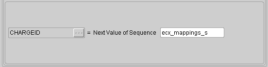
See Map Action Editor - Overview for details on the common components of the window.
Result Variable
Select the source, target, or global variable to store the next value of the sequence identified.
Next Value of Sequence
Identify the database sequence name. The function will assign the next value from the sequence to the result variable.
Map Action Editor - Database Functions: Append Where Clause
The Append Where Clause action is used for outbound messages only. It is used to pass the document selection criteria to the database views used in the transaction map.
The Append Where Clause action is defined in the source at the document level as a preprocess activity. The bind variables and bind values are set up in advance of the document being processed. The actual bind to the database views occurs as an in-process activity when the data becomes available. The default where clause of "where 1=1" is appended at runtime to dynamically construct the where clause based on the selection criteria provided.
Each Append Where Clause action accepts one set of a bind variable and a bind value. To pass multiple selection criteria, you must define multiple Append Where Clause actions.
The document selection criteria are identified in the event and event subscription.
If you are using the ECX_OAG_CONTROLAREA_V view in your map, you will need to bind to the TRANSACTION_TYPE and TRANSACTION_SUBTYPE columns for this view to execute properly.
If you are using the ECX_OAG_CONTROLAREA_TP_V view in your map, you will need to bind to the TRANSACTION_TYPE, TRANSACTION_SUBTYPE, PARTY_ID, PARTY_SITE_ID, and PARTY_TYPE columns for this view to execute properly.
Note: You must add the ECX_EVENT_MESSAGE item attribute to your Workflow item type to have access to the event details stored in the REFERENCE ID column of the ECX_OAG_CONTROLAREA_TP_V view.
The following table shows an example:
| Where Clause | Bind Variable | Bind Value |
|---|---|---|
| and ECX_OAG_CONTROLAREA_TP_V.TRANSACTION_TYPE=:TTYPE | TYPE | TRANSACTION_TYPE |
| and ECX_OAG_CONTROLAREA_TP_V.TRANSACTION_SUBTYPE=:SUBTYPE | SUBTYPE | TRANSACTION_SUBTYPE |
| and ECX_OAG_CONTROLAREA_TP_V.PARTY_ID=:PARTY_ID | PARTY_ID | TP_ID |
| and ECX_OAG_CONTROLAREA_TP_V.PARTY_SITE_ID=:PARTY_SITE_ID | PARTY_SITE_ID | TP_SITE_ID |
| and ECX_OAG_CONTROLAREA_TP_PARTY_TYPE=:PARTY_TYPE | PARTY_TYPE | TP_TYPE |
| and <APPS_HEADER_V>.<document id> =:DOCID | DOCID | document_id |
Note: For this method, use the Create Global Variable action to define variables to store the bind value. The global variables must be defined with the exact spelling of the parameters. In this example, the global variables are TRANSACTION_TYPE, TRANSACTION_SUBTYPE, TP_ID, TP_SITE_ID, TP_TYPE, and DOCUMENT_ID.
The following are reserved names for global variables:
-
TRANSACTION_TYPE
-
TRANSACTION_SUBTYPE
-
DOCUMENT_ID
-
TP_SITE_ID (also known as PARTY_SITE_ID)
-
TP_ID (also known as PARTY_ID)
-
TP_TYPE (also known as PARTY_TYPE)
-
PARAMETER1, PARAMETER2, PARAMETER3, PARAMETER4, and PARAMETER5
Other source variables not related to the event triggering process can be used as bind values to ensure that the correct document is selected from the Oracle E-Business Suite database.
If you know the key values, you can define them in your where clause. With this method, you do not have to use the Bind Variable and Bind Value. The following table shows an example:
| Where Clause | Bind Variable | Bind Value |
|---|---|---|
| and ECX_OAG_CONTROLAREA_TP_V.TRANSACTION_ TYPE ='POO' | N/A | N/A |
| and ECX_OAG_CONTROLAREA_TP_V.TRANSACTION_ SUBTYPE ='POOB' | N/A | N/A |
| and ECX_PO_HEADER_V.PO_NUMBER ='A754739' | N/A | N/A |
Note: Literal strings must be bound by single quotes.
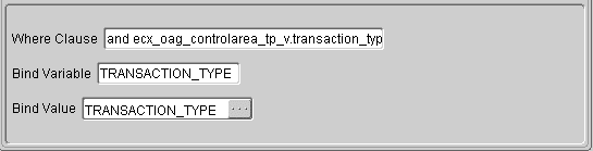
See Map Action Editor - Overview for details on the common components of the window.
The Optional Conditional Expression is not available for the Append Where Clause action because it is a preprocess action and therefore the data is not available yet.
Where Clause
Identify the where clause to bind the database views used for the outbound message. This where clause will be appended to the default where clause of "where 1=1".
If you have multiple selection criteria based on the same database view, define an Append Where Clause action for each of the criteria. Define all fields for the first Append Where Clause action (Where Clause, Bind Variable, and Bind Value). For the subsequent Append Where Clause actions, define only the Bind Variable and Bind Value (leaving the Where Clause blank).
Bind Variable
Identify the bind variable to be used by the where clause.
Bind Value
Identify the bind value to be assigned to the bind variable used by the where clause.
The bind value is a global variable whose value is determined at run time, or a literal value.
Map Action Editor - Database Functions: Insert into Database Table
The Insert into Database Table action is a postprocess action used for inbound messages to insert the data into Application Open Interface tables identified in the message map. This action is available only if the target is database.
This action must be executed once for each target level identified in the Transaction Map - Level Mapping tab. If the target has three levels (header, line, and line detail), then it must be executed three times.
You can identify a condition for the Insert into Database Table action. The action does not require any operands.
The inserts are performed by the XML Gateway Execution Engine but are not committed to the database until the entire document is processed. This eliminates the possibility of inserting a partial document into the database.
Note: An alternate way to insert data is to use the Procedure Call action to execute an Application API. See How to Map to an API for details.
See Map Action Editor - Overview for details on the common components of the window.
Map Action Editor - Derivations: Derive Address ID from Location Code
The Derive Address ID from Location Code action is used for inbound messages only. It uses the source location code and associated address type to derive the address and organization ID meaningful to the target Oracle E-Business Suite module.
The IDs are meaningful in the context of Oracle E-Business Suite only. The sender is not expected to know a valid address or organization ID.
If the parent table ID for the customer or supplier site is also required by the Application Open Interface, use the Derive Parent ID from Location Code action to derive it.
Location code is commonly used to refer to the address site represented by the physical address. Using location codes eliminates the need to include the physical address in an XML message. For OAG messages, the location code is commonly found in the PARTNRID element of the PARTNER data type.
The Derive Address ID from Location Code action will access all trading partner locations across all organizations to derive the address ID. If the source location code is found in multiple organizations, the action will produce an error because it cannot uniquely identify an address ID.
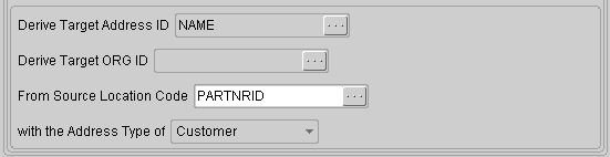
See Map Action Editor - Overview for details on the common components of the window.
Derive Target Address ID
Identify the target variable to store the address ID derived from the source location code. The value for the target variable is determined at runtime.
The target variable cannot be a global variable unless you are using it as a temporary variable to populate multiple application columns with the same value. The target variable cannot be a literal value.
Derive Target ORG ID
Identify the target variable to store the organization ID derived from the source location code. The value for the target variable is determined at runtime.
The target variable cannot be a global variable unless you are using it as a temporary variable to populate multiple application columns with the same value. The target variable cannot be a literal value.
From Source Location Code
Identify the source variable containing the location code. The source variable can be a global variable, whose value is determined at runtime, or a literal value.
With the Address Type of
Select the address type from the list of values. The valid address types are as follows:
-
Customer
-
Supplier
-
Internal Location
-
Bank Branch
This address type is used by the XML Gateway Execution Engine to determine the appropriate Oracle address data model to access to derive the address ID.
Map Action Editor - Derivations: Derive Parent ID from Location Code
The Derive Parent ID from Location Code action is used for inbound messages only. It derives the Parent ID associated with the site level source location code.
For example, given a SOLD-TO site in the XML message, this action will derive the parent customer associated with it.
Keep in mind that IDs are meaningful in the context of Oracle E-Business Suite only. The sender is not expected to know a valid parent ID.
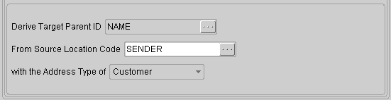
See Map Action Editor - Overview for details on the common components of the window.
Derive Target Parent ID
Identify the target variable to store the parent ID derived from the site level source location code. The value for the target variable is determined at runtime.
The target variable cannot be a global variable unless you are using it as a temporary variable to populate multiple application columns with the same value. The target variable cannot be a literal value.
From Source Location Code
Identify the source variable containing the location code. The source variable can be a global variable, whose value is determined at runtime, or a literal value.
With the Address Type of
Select the address type from the list of values. The valid address types are as follows:
-
Customer
-
Supplier
-
Internal Location
-
Bank Branch
This address type is used by the XML Gateway Execution Engine to determine the appropriate Oracle address data model to access to derive the address ID.
Map Action Editor - Function Call: Execute Function Call
The Execute Function action calls a system function (for example, FND_GLOBAL.USER_ID) or any application function to perform an activity and return the result to the result variable.
Function calls with parameters are not supported by the Execute Function Call action.
See XML Gateway APIs for a list of special purpose functions.
Note: Procedure calls are not supported by the Execute Function Call action. See Map Action Editor - Procedure Call: Execute Procedure for details on how to enable a procedure.
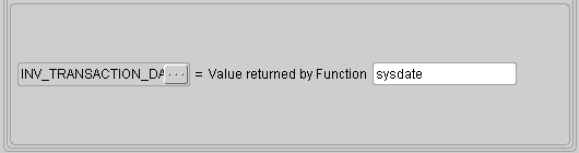
See Map Action Editor - Overview for details on the common components of the window.
Result Variable
Select the source, target, or global variable to store the function return value.
Value Returned by Function
Identify the name of the Function. The value returned by the function will be assigned to the result variable.
Map Action Editor - Math Functions
Oracle XML Gateway supports the four basic math functions: addition, subtraction, multiplication, and division.
Each math function supports two operands. The Add, Subtract, Divide, and Multiply functions will each display the appropriate operators.
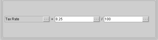
If the mathematical expression requires more than two operands, compute the expression two operands at a time, store the result in a temporary variable (source, target, or global), and then join the values in the temporary variables.
Note: Use the Function Call or Procedure Call action to utilize database level functions for complex mathematical computations.
See Map Action Editor - Overview for details on the common components of the window.
Result Variable
Select the source, target, or global variable to store the result of the mathematical computation.
Action Operands
Identify the two operands and the math function desired.
Each operand may be a variable (source, target, or global variables if defined) whose value is determined at runtime, or a numeric literal value.
OAG Conversions
The availability of the OAG Conversion actions depends on the source and target. The following table summarizes when the actions are enabled:
| Source | Target | OAG Actions |
|---|---|---|
| xml/dtd (OAG) | xml/dtd (OAG) | Both From and To actions are enabled. |
| xml/dtd (OAG) | database | Only From actions are enabled. |
| database | xml/dtd (OAG) | Only To actions are enabled. |
| xml/dtd (OAG) | xml/dtd (cXML) | Only From actions are enabled. |
| xml/dtd (cXML) | xml/dtd (OAG) | Only To actions are enabled. |
| xml/dtd (cXML) | database | None of the OAG actions are enabled. |
| database | xml/dtd (cXML) | None of the OAG actions are enabled. |
Map Action Editor - Convert to OAG DATETIME
The Convert To OAG DATETIME action converts the Oracle E-Business Suite representation for date to the OAG representation for date. This action is disabled if the target is database.
The OAG representation for date is as follows:
DATETIME (qualifier, type, index, YEAR, MONTH, DAY, HOUR, MINUTE, SECOND, SUBSECOND, TIMEZONE)
The Convert to OAG DATETIME action converts the single column Oracle E-Business Suite date to the OAG DATETIME segment as follows:
-
The DATETIME attributes for qualifier, type, and index must be set as default values in the Target Definition tab of the Transaction Map window.
-
The DATETIME elements for YEAR, MONTH, DAY, HOUR, MINUTE, SECOND, and SUBSECOND are derived based on the Oracle E-Business Suite date value.
-
The DATETIME element for TIMEZONE is determined as follows: The date and time data retrieved from the database, along with the value specified in the ECX: Server Time Zone profile option, are used to determine the Greenwich Mean Time (GMT) deviation. The deviation is used in the XML message generated by XML Gateway. No conversion is performed.
See XML Gateway Valid Time Zone Values for more information.
Note: The source and target elements are implicitly mapped via the Action. Additional element mapping will overwrite the original Action instructions.
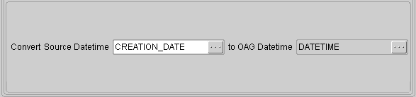
See Map Action Editor - Overview for details on the common components of the window.
Convert Source Datetime
Identify the source date/time element to be converted into the OAG DATETIME format. The source can be a literal value defined using a numeric format (such as 20020808 for 08-Aug-2002). Literal dates entered using a character format (such as 08-Aug-2002) are not valid.
Target and variables do not apply although they are available in the Element window.
The converted value will be assigned to the target DATETIME element selected when the action was invoked.
Map Action Editor - Convert to OAG OPERAMT
The Convert To OAG OPERAMT action converts the Oracle E-Business Suite representation for operating amount to the OAG representation for operating amount.
The OAG representation for operating amount is as follows:
OPERAMT (qualifier, type, VALUE, NUMOFDEC, SIGN, CURRENCY, UOMVALUE, UOMNUMDEC, UOM)
The Convert to OAG OPERAMT action converts the single column Oracle E-Business Suite operating amount to the OAG OPERAMT segment as follows:
-
The OPERAMT attributes for qualifier and type must be set as default values in the Target Definition tab of the Transaction Map window.
-
The OPERAMT elements for VALUE, NUMOFDEC, SIGN, UOMVALUE, and UOMNUMDEC are derived based on the Oracle E-Business Suite operating amount value.
-
The OPERAMT elements for CURRENCY and UOM are prompted for. If the appropriate Oracle E-Business Suite application columns are available, the values from the columns can be mapped to the CURRENCY and UOM elements.
Note: The source and target elements are implicitly mapped via the Action. Additional element mapping will overwrite the original Action instructions.
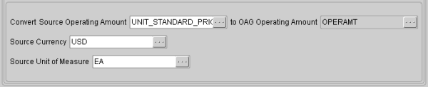
See Map Action Editor - Overview for details on the common components of the window.
Convert Source Operating Amount
Identify the source operating amount element to be converted into the OAG OPERAMT format. The source can be a literal value or based on a global variable. The literal or variable must be numeric.
Target variables do not apply although they are available in the Element window.
The converted value is assigned to the target OPERAMT element selected when the Action was invoked.
Source Currency
Identify the source currency code element if available or a literal value to be used by the Convert To OAG Action.
If an Oracle E-Business Suite application column is available, the value from the column can be mapped to the CURRENCY element.
If no Oracle E-Business Suite application column is available, the XML Gateway Execution Engine will leave the element blank.
Target and global variables do not apply although they are available in the Element window.
Source Unit of Measure
Identify the source unit of measure code element if available or a literal value to be used by the Convert To OAG Action.
If an Oracle E-Business Suite application column is available, the value from the column can be mapped to the UOM element.
If no Oracle E-Business Suite application column is available, the XML Gateway Execution Engine will default the unit of measure code to EACH as recommended by OAG.
Target and global variables do not apply although they are available in the Element window.
Map Action Editor - Convert to OAG QUANTITY
The Convert To OAG QUANTITY action converts the Oracle E-Business Suite representation for quantity to the OAG representation for quantity.
The OAG representation for quantity is as follows:
QUANTITY (qualifier, VALUE, NUMOFDEC, SIGN, UOM)
The Convert to OAG QUANTITY action converts the single column Oracle E-Business Suite quantity to the OAG QUANTITY segment as follows:
-
The QUANTITY attribute for qualifier must be set as a default value in the Target Definition tab of the Transaction Map window.
-
The QUANTITY elements for VALUE, NUMOFDEC, and SIGN are derived based on the Oracle E-Business Suite quantity value.
-
The QUANTITY element for UOM is prompted for. If the appropriate Oracle E-Business Suite module column is available, the value from the column can be mapped to the UOM element.
Note: The source and target elements are implicitly mapped via the Action. Additional element mapping will overwrite the original Action instructions.
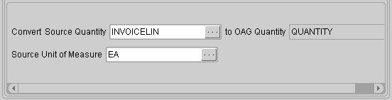
See Map Action Editor - Overview for details on the common components of the window.
Convert Source Quantity
Identify the source quantity element to be converted into the OAG QUANTITY format. The source can be a literal (numeric) value or based on a global variable.
Target variables do not apply although they are available in the Element window.
The converted value is assigned to the target QUANTITY element selected when the action was invoked.
Source Unit of Measure
Identify the source unit of measure code element if available, or a literal value to be used by the Convert To OAG Action.
If an Oracle E-Business Suite application column is available, the value from the column can be mapped to the UOM element.
If no Oracle E-Business Suite application column is available, the XML Gateway Execution Engine will leave the element blank.
Target and global variables do not apply although they are available in the Element window.
Map Action Editor - Convert to OAG AMOUNT
The Convert To OAG AMOUNT action converts the Oracle E-Business Suite representation for amount to the OAG representation for amount.
The OAG representation for amount is as follows:
AMOUNT (qualifier, type, index, VALUE, NUMOFDEC, SIGN, CURRENCY, DRCR)
The Convert to OAG AMOUNT action converts the single column Oracle E-Business Suite amount to the OAG AMOUNT segment as follows:
-
The AMOUNT attribute for qualifier, type, and index must be set as default values in the Target Definition tab of the Transaction Map window.
-
The AMOUNT elements for VALUE, NUMOFDEC, and SIGN will be derived based on the Oracle E-Business Suite amount value.
-
The AMOUNT element for CURRENCY and DRCR are prompted for. If the appropriate Oracle E-Business Suite columns are available, the values from the columns can be mapped to the CURRENCY and DRCR elements.
Note: The source and target elements are implicitly mapped via the Action. Additional element mapping will overwrite the original Action instructions.
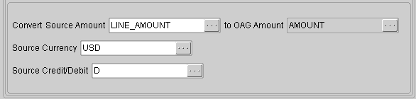
See Map Action Editor - Overview for details on the common components of the window.
Convert Source Amount
Identify the source amount element to be converted into the OAG AMOUNT format. The source can be a literal (numeric) value or based on a global variable.
Target variables do not apply although they are available in the Element window.
The converted value is assigned to the target AMOUNT element selected when the action was invoked.
Source Currency
Identify the source currency code element if available or a literal value to be used by the Convert To OAG Action.
If an Oracle E-Business Suite application column is available, the value from the column can be mapped to the CURRENCY element.
If no Oracle E-Business Suite application column is available, the XML Gateway Execution Engine will leave the element blank.
Target and global variables do not apply although they are available in the Element window.
Source Credit/Debit
Identify the source credit/debit flag if available or a literal value to be used by the Convert To OAG Action.
If an Oracle E-Business Suite application column is available, the value from the column can be mapped to the DRCR element.
If no Oracle E-Business Suite application column is available, the XML Gateway Execution Engine will derive the setting based on the amount value.
Target and global variables do not apply although they are available in the Element window.
Map Action Editor - Convert from OAG DATETIME
The Convert From OAG DATETIME action converts the OAG representation for date to the Oracle E-Business Suite representation for date. This action is disabled if the source is database.
The OAG representation for date is as follows:
DATETIME (qualifier, type, index, YEAR, MONTH, DAY, HOUR, MINUTE, SECOND, SUBSECOND, TIMEZONE)
The Convert From OAG DATETIME action converts the OAG DATETIME segment to the single Oracle E-Business Suite date column as follows:
-
The DATETIME qualifier attribute can be used to determine the appropriate Oracle E-Business Suite date column to use.
-
The DATETIME attributes for type and index are not used by Oracle E-Business Suite.
-
The DATETIME elements for YEAR, MONTH, DAY, HOUR, MINUTE, SECOND, and SUBSECOND are used to construct the Oracle E-Business Suite date value.
-
The DATETIME element for TIMEZONE is determined as follows: if the time zone of the incoming message is different from the time zone specified in the profile option ECX: Server Time Zone, the incoming date and time are converted.
See XML Gateway Valid Time Zone Values for more information.
Note: The source and target elements are implicitly mapped via the Action. Additional element mapping will overwrite the original Action instructions.
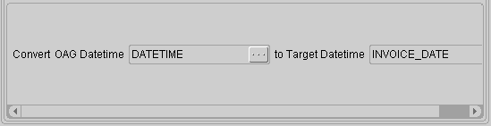
See Map Action Editor - Overview for details on the common components of the window.
Convert OAG Datetime
Identify the source DATETIME element to be converted into the Oracle E-Business Suite format. The source can be a literal value.
Target variables do not apply although they are available in the Element window.
The converted value is assigned to the application (target) date element selected when the action was invoked.
Map Action Editor - Convert from OAG OPERAMT
The Convert From OAG OPERAMT action converts the OAG representation for operating amount to the Oracle E-Business Suite representation for operating amount.
The OAG representation for operating amount is as follows:
OPERAMT (qualifier, type, VALUE, NUMOFDEC, SIGN, CURRENCY, UOMVALUE, UOMNUMDEC, UOM)
The Convert From OAG OPERAMT action converts the OAG OPERAMT segment to the single Oracle E-Business Suite operating amount column as follows:
-
The OPERAMT qualifier attribute can be used to determine the appropriate Oracle E-Business Suite application module operating amount column to use.
-
The OPERAMT type attribute is not used by Oracle E-Business Suite.
-
The OPERAMT elements for VALUE, NUMOFDEC, SIGN, UOMVALUE, and UOMNUMDEC are used to construct the Oracle E-Business Suite operating amount value.
-
The OPERAMT elements for CURRENCY and UOM can be stored in Oracle E-Business Suite if the appropriate columns are available.
Note: The source and target elements are implicitly mapped via the Action. Additional element mapping will overwrite the original Action instructions.
See Map Action Editor - Overview for details on the common components of the window.
Convert OAG Operating Amount
Identify the source OPERAMT element to be converted into the Oracle E-Business Suite format. The source can be a literal value.
Target variables do not apply although they are available in the Element window.
The converted value is assigned to the application (target) operating amount element selected when the action was invoked.
Target Currency
The source OPERAMT value is represented as a collection of subcomponents. Identify the application (target) element to store the currency code. Literal values are not allowed.
If an application (target) element is identified, the Convert From OAG Action will move the source currency code to it.
If no application (target) element is identified, the source currency code will be ignored.
Target Unit of Measure
The source OPERAMT value is represented as a collection of subcomponents. Identify the application (target) element to store the unit of measure code. Literal values are not allowed.
If an application (target) element is identified, the Convert From OAG Action will move the source unit of measure code to it.
If no application (target) element is identified, the source unit of measure code will be ignored.
Map Action Editor - Convert from OAG Quantity
The Convert From OAG QUANTITY action converts the OAG representation for quantity to the Oracle E-Business Suite representation for quantity.
The OAG representation for quantity is as follows:
QUANTITY (qualifier, VALUE, NUMOFDEC, SIGN, UOM)
The Convert From OAG QUANTITY action converts the OAG QUANTITY segment to the single Oracle E-Business Suite quantity column as follows:
-
The QUANTITY qualifier attribute can be used to determine the appropriate Oracle E-Business Suite quantity column to use.
-
The QUANTITY elements for VALUE, NUMOFDEC, and SIGN are used to construct the Oracle E-Business Suite quantity value.
-
The QUANTITY element for UOM may be stored in Oracle E-Business Suite if an appropriate column is available.
Note: The source and target elements are implicitly mapped via the Action. Additional element mapping will overwrite the original Action instructions.
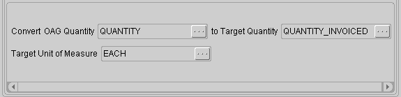
See Map Action Editor - Overview for details on the common components of the window.
Convert OAG Quantity
Identify the source QUANTITY element to be converted into the Oracle E-Business Suite format.
Target variables do not apply although they are available in the Element window.
The converted value is assigned to the application (target) quantity element selected when the action was invoked.
Target Unit of Measure
The source QUANTITY value is represented as a collection of subcomponents. Identify the application (target) element to store the unit of measure code. Literal values are not allowed.
If an application (target) element is identified, the Convert From OAG Action will move the source unit of measure code to it.
If no application (target) element is identified, the source unit of measure code will be ignored.
Map Action Editor - Convert from OAG AMOUNT
The Convert From OAG AMOUNT action converts the OAG representation for amount to the Oracle E-Business Suite representation for amount.
The OAG representation for amount is as follows:
AMOUNT (qualifier, type, index, VALUE, NUMOFDEC, SIGN, CURRENCY, DRCR)
The Convert From OAG AMOUNT action converts the OAG AMOUNT segment to the single Oracle E-Business Suite amount column as follows:
-
The AMOUNT qualifier attribute can be used to determine the appropriate Oracle E-Business Suite amount column to use.
-
The AMOUNT attributes for type and index are not used by Oracle E-Business Suite.
-
The AMOUNT elements for VALUE, NUMOFDEC, and SIGN are used to construct the Oracle E-Business Suite amount value.
-
The AMOUNT elements for CURRENCY and DRCR can be stored in Oracle E-Business Suite if appropriate columns are available.
Note: The source and target elements are implicitly mapped via the Action. Additional element mapping will overwrite the original Action instructions.
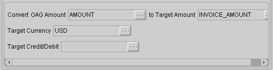
See Map Action Editor - Overview for details on the common components of the window.
Convert OAG Amount
Identify the source AMOUNT element to be converted into the Oracle E-Business Suite format. The source can be a literal value.
Target variables do not apply although they are available in the Element window.
The converted value is assigned to the application (target) amount element selected when the action was invoked.
Target Currency
The source AMOUNT value is represented as a collection of subcomponents. Identify the application (target) element to store the currency code. Literal values are not allowed.
If an application (target) element is identified, the Convert From OAG Action will move the source currency code to it.
If no application (target) element is identified, the source currency code will be ignored.
Target Credit/Debit
The source AMOUNT value is represented as a collection of subcomponents. Identify the application (target) element to store the credit/debit flag. Literal values are not allowed.
If an application (target) element is identified, the Convert From OAG Action will move the source credit/debit flag to it.
If no application (target) element is identified, the source credit/debit flag will be ignored.
Map Action Editor - Other: Exit Program
The Exit Program action can be executed based on the result of executing a Procedure call, Function call, or retrieving the value of a Predefined Variable.
The Exit Program action rolls back the current transaction and exits the XML Gateway Execution Engine.
The Exit Program action has no additional operands.
See Map Action Editor - Overview for details on the common components of the window.
Map Action Editor - Get Predefined Variable Value
The Get Predefined Variable Value action maintains predefined variables for the following:
-
Inbound message envelope
-
Code conversion status
-
Transaction status
The values of these predefined variables are maintained by the XML Gateway Execution Engine and are available for inquiry and mapping to the Application Open Interface table column or Application API parameter.
You can control the process flow based on the values found in the predefined variables.
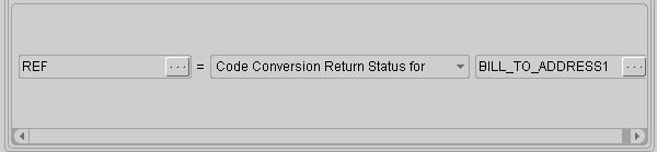
See Map Action Editor - Overview for details on the common components of the window.
Result Variable
Select the source, target, or global variable to store the value of the predefined variable selected.
Predefined Variables
Select the predefined variable whose value you are interested in. The variables exposed by the XML Gateway Execution Engine are as follows:
Code Conversion Return Status for
Select the source column enabled for code conversion. The code conversion process will search the trading partner-specific code conversions and then the standard-specific list, followed by the universal list.
The status of the code conversion is assigned to the result variable. The return status codes are shown in the following table:
| Return Status Code | Description |
|---|---|
| 0 | Code conversion was successful. |
| 1 | Code conversion process failed to find a match for the source column, the source value is copied to the target column. This is a warning only. It will not stop the XML Gateway Execution Engine. However, you may wish to take some action to control the process flow based on this status. The possible causes of this failure are: invalid code category passed to the code conversion API or code conversion cross-reference not found. Verify that the code category identified for the source column is valid (Refer to Seeded Code Categories) and that a code conversion cross-reference is defined in the trading partner-specific list, the standard-specific list, or the universal list. Make the necessary corrections to prevent this error from occurring again. |
| 2 | Code conversion process encountered unexpected error, session is terminated. Check the process log file for the details, make the necessary correction, and reprocess the message. |
Internal Control Number
The Internal Control Number is a system-generated number that uniquely identifies the XML message being processed. This number is useful for sending acknowledgments, for document audits, for document archival, and for troubleshooting.
The value for the Internal Control Number is assigned to the result variable identified for the action.
The Internal Control Number can be used to get envelope information. Refer to ECX_TRADING_PARTNER_PVT.getEnvelopeInformation API for more information.
Return Code
The Return Code is the error code associated with the error message. The error message may be returned to the trading partner contact or the XML Gateway system administrator using the Send Error Message action.
Multiple return codes can be concatenated in a single predefined variable. The value for the Return Code is assigned to the result variable.
The possible return codes are shown in the following table:
| Return Code | Description |
|---|---|
| 0 | Success |
| 1 | Warning. The XML Gateway Execution Engine will not be stopped. |
| 2 | Failure. Check the process log file for the details, make the necessary corrections, and reprocess the message. |
Return Message
The Return Message is the text associated with the return code. The error message may be returned to the trading partner contact or the XML Gateway system administrator using the Send Error Message action.
Multiple return messages can be concatenated in a single predefined variable. The value for the Return Message is assigned to the result variable.
Receiver Trading Partner ID
The Receiver Trading Partner ID is a unique identifier for the receiver of the XML message. The ID can be used to derive the trading partner name and other pertinent data.
Use the ECX_TRADING_PARTNER_PVT.get_receivers_tp_info procedure to derive the Party ID, Party Site ID, Organization ID, and Administrator e-mail Address associated with the Receiver Trading Partner ID. Refer to XML Gateway APIs for more information.
The Receiver Trading Partner ID is maintained for outbound messages and pass-through messages.
The value for the Receiver Trading Partner ID is assigned to the result variable.
Sender Trading Partner ID
The Sender Trading Partner ID is a unique identifier for the sender of the XML message. The ID may be used to derive the trading partner name and other pertinent data.
Use the ECX_TRADING_PARTNER_PVT.get_senders_tp_info procedure to derive the Party ID, Party Site ID, Organization ID, and Administrator e-mail Address associated with the Sender Trading Partner ID. Refer to XML Gateway APIs for more information.
The Sender Trading Partner ID is maintained for inbound messages and pass-through messages.
The value for the Sender Trading Partner ID is assigned to the result variable.
Organization ID
The Execution Engine derives the organization ID associated with the Sender or Receiver Trading Partner ID. The combination of the organization ID and the Sender or Receiver Trading Partner ID uniquely identifies a trading partner in the Oracle E-Business Suite.
Map Action Editor - Procedure Call: Execute Procedure
The Execute Procedure action calls a procedure to perform an activity. Some procedures have input (send) parameters as well as output (return) parameters, while others have no parameters at all.
The Execute Procedure action connects to the database to provide a list of available procedures for selection. Once you select the procedure, you will be prompted for the parameter values.
Function calls are not supported by the Execute Procedure action.
See Message Designer APIs for a list of special purpose procedures for use with the Message Designer.
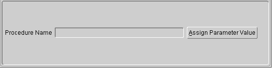
See Map Action Editor - Overview for details on the common components of the window.
Click the Assign Parameter Value button to invoke the Get Procedure Parameters... window.
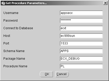
This window requests database connection information. The default database access information is displayed from the Database tab of the File > Properties menu. The defaults can be overwritten on this screen. Changes made on this screen are not copied back to the Properties file. Changes are used for the current session only.
Enter the Schema Name, Package Name, and Procedure Name and click OK.
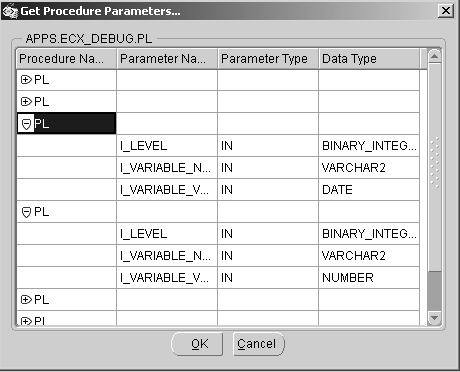
After connecting to the database, the window displays all signatures for the procedure. Expand all the signatures by clicking the "+". Select the procedure from the expanded list and click OK.
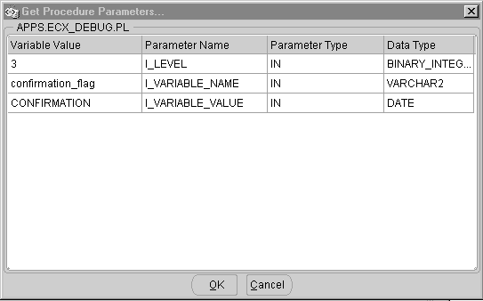
Enter the parameter values in this window. A parameter value may be a literal value, from a source or target, or a global variable.
Regardless of how the parameters are defined in the procedure, a value is required (by the XML Gateway Execution Engine) for each parameter with a Parameter Type of IN unless a default value is provided by the procedure. The value can be based on a source variable, target variable, global variable (if defined), or a literal value. The value for the source, target, or global variable is determined at run time.
For procedures with return variables (Parameter Type of OUT), define temporary variables or use existing variables (source, target, or global) to store the return values. Status return values can be used to redirect the process flow based on severity. Return error codes and messages can be sent to the XML Gateway system administrator or Trading Partner contact using the Send Error Message action.
The XML Gateway Execution Engine supports parameters with a data type of VARCHAR2, DATE, NUMBER, CHAR, and CLOB. If the required procedure contains parameters of unsupported data types, the parameter values must be converted to a supported data type in order to utilize this action.
For parameters defined with default values, you can provide another variable or literal value if you wish to overwrite the default value.
Once you have entered all the required parameter values, click OK to return to the Map Action Editor window.
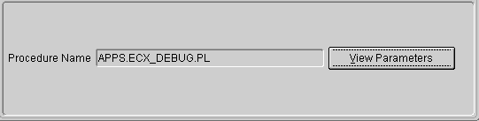
The procedure selected is displayed in the Procedure Name field. Click on the View Parameters button to review the parameter values entered. Verify the parameter values, make any necessary corrections, and click OK to return to the Map Action Editor window.
Map Action Editor - Return Error Message: Send Error Message
The Send Error Message action sends an error message to either the Trading Partner contact or the XML Gateway system administrator identified in the ECX_SYS_ADMIN_EMAIL system profile.
The Send Error Message Action is used for warnings that do not require the process to be terminated. For more serious errors requiring termination of the process, use the ECX_ACTIONS.set_error_exit_program API. See set_error_exit_program for more information about its usage.
Error messages can be obtained from the following sources:
-
Return parameter of a procedure call
-
Status of a function call
A Workflow notification containing the error message is sent to the party identified in the To prompt.
This action is provided to augment the standard error handling and notification process.
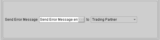
See Map Action Editor - Overview for details on the common components of the window.
Send Error Message
Identify the variable containing the error message to be sent. The error message can be represented as a literal.
When using this action in conjunction with the Procedure Call action, the variable may be a return parameter or a literal value.
When using this action in conjunction with the Function Call action, the variable may be the function return value or the value contained in the Return Message variable maintained by the XML Gateway Execution Engine.
You can concatenate several strings such as the value in Return Message with a literal value to form a complete message.
To
Identify the recipient of the error message. The valid options are the Trading Partner contact or the XML Gateway system administrator, identified in the ECX_SYS_ADMIN_EMAIL system profile.
Map Action Editor - String Functions: Perform Concatenation
The Perform Concatenation action concatenates the values in two operands. The operands can be based on variables whose values are determined at runtime, or based on literal values.
To concatenate more than two operands, start with the first two operands and store the result in a variable (source, target, or global). Then concatenate the value in the variable with the next operand.
The Perform Concatenation action can be applied to fields of any data type because the XML Gateway Execution Engine will convert the value to VARCHAR2 before performing the action.
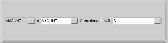
See Map Action Editor - Overview for details on the common components of the window.
Result Variable
Select the source, target, or global variable to store the resulting concatenated string.
First Operand
Identify the first operand.
The operand can be a variable (source, target, or global variable if defined) whose value is determined at runtime, or a literal value.
Concatenated With
Identify the second operand to be concatenated with the first operand.
The operand can be a variable (source, target, or global variable if defined) whose value is determined at runtime, or a literal value.
The concatenated value is assigned to the result variable.
Map Action Editor - String Functions: Perform Substring
The Perform Substring action parses a given string from a start position and includes the characters within the length specified. The resulting substring is returned.
The Perform Substring action can be applied to fields of any data type because the XML Gateway Execution Engine will convert the value to VARCHAR2 before performing the action.
Refer to ECX_CONDITIONS Package APIs for additional substring functions.
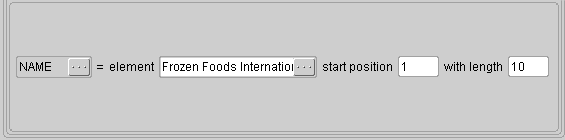
See Map Action Editor - Overview for details on the common components of the window.
Result Variable
Select the source, target, or global variable to store the resulting substring.
Element
Identify the operand requiring substring action.
The operand can be a variable (source, target, or global variable if defined) whose value is determined at runtime, or a literal value.
Start Position
Enter a start position greater then 0 but less than the maximum length of the Element.
With Length
Enter a length greater than 0 but less than or equal to the maximum length of the Element minus the start position.
The substring function will process the element identified from the start position up to the length specified and assign the resulting substring to the result variable.
Map Action Editor - XSLT Transformation
XML Gateway supports XSLT transformations for both inbound and outbound messages. An XSLT style sheet can be applied to an XML message before it is enqueued for delivery to a Trading Partner.
The file containing the XSLT style sheet must be stored in the directory defined by the ECX_UTL_XSLT_DIR system profile. The XML Parser applies the transformation as the last activity performed before an outbound message is sent, or as the first activity before an inbound message is processed.
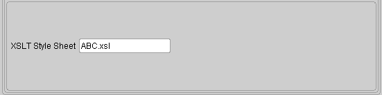
See Map Action Editor - Overview for details on the common components of the window.
XSLT Style Sheet
The XSLT Stylesheet name can be a literal file name (such as ABC.xsl) or a Global Variable (such as PARAMETER6).
How to Extend DTDs
The XML Gateway Message Designer supports mapping to and from a DTD or an existing XML message. The use of an existing production XML message provides visibility to all the DTD extensions as well as duplicate nodes and elements necessary to support the actual business document. The use of a DTD is necessary if an existing XML message is not available. Using a DTD may require adding duplicate nodes, new segments, or elements to accommodate additional data.
When modifying an Oracle prebuilt message map or when creating a new message map that requires DTD extensions, follow the DTD extension guidelines outlined below. The Open Applications Group (OAG) has very strict guidelines regarding DTD extensions.
The only DTD extensions allowed are in the USERAREA. You can add elements in the appropriate OAG defined USERAREA or create new USERAREAs under the OAG defined USERAREA.
Refer to the OAG guidelines section 2.11 titled "USERAREA Extensions" in the Open Application Group's Integration Specification (available at http://www.openapplications.org).
Use USERAREAs to support descriptive flexfields as well as other extensions.
The OAG guidelines are as follows:
| Top Level Name | <vendor.transaction.context.USERAREA> |
| Element Name | <vendor.elementname> |
| Reference File Name | <vendor prefix>_<product>_<version>.dtd |
Oracle's adaptation of the OAG guidelines is as follows:
| Top Level Name for Descriptive Flexfield Extensions | <Oracle.transaction.name of flexfield.USERAREA> Example: Oracle.ARInvoice.ARLINES.USERAREA |
| Element Name | <Oracle.attributen> where n is the number of attributes defined for the table |
| Top Level Name for other Extensions | <Oracle.transaction.product_prefix.USERAREA> Example: Oracle.ARInvoice.AR.USERAREA |
| Element Name | <Oracle.elementname> |
| Reference File Name | Oracle_<application shortname>DTDExtensions_<version>.dtd Example: Oracle_ARDTDExtensions_001.dtd |
XML Gateway provides a template to be used as the basis to create the application-specific DTD extensions. The template contains a definition for the generic flexfields named "attribute*" where * is the number of attributes defined for the table. The application-specific DTD extension files are source-controlled with the specific application.
The application-specific DTD extension file can be updated as follows:
-
Top level USERAREA names representing the application table containing the descriptive flexfields
-
Descriptive flexfield names
-
Top level USERAREA names for other extensions
-
Element names for other extensions
The updates must be added after the existing USERAREA tag.
Use Conditional Node Mapping and key on Top Level USERAREA name to ensure that you are mapping from and to the correct group of flexfields or application extensions.
Be sure to remove extension definitions from the reference file if you are removing them from the message map.
Update the message map to incorporate the new fields introduced as a DTD extension. The updated message map and DTD extension files must be loaded in the XML Gateway repository for access by the XML Gateway Execution Engine. Refer to How to Load/Delete Message Maps and DTDs for the details.
How to Map a Pass-Through Message
Pass-through messages are messages that are received by Oracle Exchange for code conversion (if required) and then routed to a final destination. Oracle Exchange acts as a routing hub for these messages.
The map for a pass-through message is defined as follows:
Note: In a pass-through message, the same DTD is used for both the source and the target. If different DTDs are used the transaction is an XML-to-XML transformation, not a pass-through.
-
Map the highest level only. The CNTROLAREA is the highest level in an OAG DTD.
-
Load the message map into the XML Gateway repository for processing. Refer to How to Load/Delete Message Maps and DTDs for details.
-
Define the Exchange hub as the trading partner and enable the XML message as a pass-through transaction. See Trading Partner Setup.
-
Define the necessary code conversions in Oracle XML Gateway or Oracle Exchange. See Code Conversion.
How to Map to an API
This section describes how to map to an API instead of an Application Open Interface Table. Data for an inbound XML message is copied to a set of staging tables known as Application Open Interface tables. The data in these staging tables are validated using an Application Open Interface API containing the business rules. Valid data is moved to the Application base tables. Invalid data is marked for review.
In the case where the staging table and the validation rules are embedded in the same code (commonly referred to as the Application API), data for an inbound XML message is mapped to the parameters of the Application API.
To map directly to an Application API, the map must be defined as follows:
-
The data definition type for the source and target must be XML.
-
The source and target DTD and version must be the same.
-
Map the source levels to the target levels.
-
Define a target action for Execute Procedure referencing the Application API as the procedure name. The action is defined at the document level as a postprocess activity. Map the source variables to the API parameters. Include an action to check the API return status.
Apply this approach for each level of the document. If the document has three levels, this approach is applied three times.
-
Load the message map and corresponding DTDs into the XML Gateway repository for processing. Refer to How to Load/Delete Message Maps and DTDs to load the maps into the XML Gateway repository.
-
Define the trading partner and enable the XML message.
-
Define any necessary code conversions.
Message Designer does not support Application APIs consisting of multiple document levels. Message Designer is designed to process data one document level at a time.
Loading and Deleting Message Maps and DTDs
Loading/Deleting a Map
Oracle message maps are delivered and installed on the $APPLTOP directory. They are automatically loaded into the XML Gateway repository using the LoadMap program. A map can be deleted using the DeleteMap program.
If you modified an Oracle prebuilt message map or created a new message map using the Message Designer, these maps are saved on your local file system. Perform the following steps to load the maps into the XML Gateway repository for use by the XML Gateway Execution Engine:
-
Move <mymap>.xgm file from the local file system to the middle tier. The apps.zip file containing the maps that were installed on the $APPLTOP is installed on the middle tier.
-
Execute java LoadMap<DB username><DB password><Hostname>:<Port>:<SID><mymap.xgm> to load the message map into the XML Gateway repository. LoadMap will replace existing maps with the same name.
Example: java LoadMap User1 welcome ap999sun.us.oracle.com:1521:ORA1151<mymap.xgm>
Note: The LoadMap process will load a map if the map version is compatible with the engine version. The map version is stored in the <ECX_MAJOR_VERSION> and the <ECX_MINOR_VERSION> tags of the map file (.xgm). The engine version is stored in WF_RESOURCES. Maps are compatible with the engine if the major version is the same and the minor version is the same or lower.
A map can be deleted using the DeleteMap program as follows:
-
Execute java DeleteMap <DB username><DB password><Hostname><:<Port>:<SID><mapcode> to delete a message map from the XML Gateway repository. LoadMap will replace existing maps with the same name, but obsolete maps with a different name must be deleted manually.
<mapcode> is the map name entered in the Message Designer.
Example: java DeleteMap User1 welcome ap222sun.us.oracle.com:1521:ORA1151<mapcode>
Loading and Deleting a DTD
Each message map is associated with a set of DTDs: the main and its reference DTDs. Similar to message maps, the DTDs associated with the Oracle prebuilt message maps are delivered and installed on the $APPLTOP. They are automatically loaded into the XML Gateway database using the LoadDTDToClob program. A DTD can be deleted using the DeleteDTDFromClob program.
To change a DTD referenced in an existing message map, use the File > Properties menu option of the Message Designer to make the necessary change. The updated message map must be loaded into the XML Gateway repository using LoadMap (refer to Loading/Deleting a Map). In addition, the new DTD used must be loaded into the XML Gateway database as follows:
-
Move <mydtd>.dtd file from the local file system to the middle tier. The apps.zip file containing the DTDs that were installed on the $APPLTOP is on the middle tier.
-
Execute java LoadDTDToClob<DB username><DB password><Hostname>:<Port>:<SID><mydtd.dtd> <RootElementName><Location> to load the DTD into the XML Gateway database. LoadDTDToClob will replace existing DTDs with the same name.
<RootElementName> is the XML Root Element entered in the Message Designer.
<Location> is the subdirectory name entered in the Specify XML File and Root Element window of the wizard.
A DTD can be deleted using the DeleteDTDFromClob program as follows:
Execute java DeleteDTDFromClob <DB username> <DB password> <Hostname>:<Port>:<SID><mydtd.dtd> <RootElementName><Location> to delete a DTD from the XML Gateway database. LoadDTDToClob will replace existing DTDs with the same name, but obsolete DTDs with a different name must be manually deleted.
<RootElementName> is the XML Root Element entered in the Message Designer.
<Location> is the subdirectory name entered in the Specify XML File and Root Element window of the wizard.
LoadMap and LoadDTDToClob are provided as two separate programs to support various combinations of changes. To ensure that the maps and DTDs are synchronized, always execute LoadMap and LoadDTDToClob as a pair.
Downloading a Map
You can download a map from the ECX table to produce the corresponding XGM file. Use the DownloadMap.java utility to download the map to the log directory.
The usage is as follows:
java DownloadMap <DB username><DB password><Hostname>:<Port>:<SID><MAP_CODE>
Note that there will be differences between the original map and the downloaded map.
Differences Between the Downloaded Map and the Original Map
The downloaded map and original map will differ as follows:
-
If the original map has a code category that is not present in ecx_xref_hdr, the downloaded map will not show the code category.
-
If the original map uses variables of data type other than VARCHAR2, CHAR, NUMBER, CLOB, or DATE, the download map will default it to VARCHAR2.
-
If the original map was created with a Message Designer version other than 2.6.0.X, the DownloadMap utility will default it to 2.6.3.0.0.
-
If the original map was created with a version of Message Designer that did not include the dbdrv hints, these hints will be present in the downloaded map.
Loading and Deleting an XSLT Style Sheet
XSLT style sheets are used to transform an XML message for rendering. The style sheets are created using an XSL editor. The xsl file can be staged in the file system or loaded into the database.
Note: The XML parser does not support nested style sheets using the xsl: import function. Define individual style sheets instead.
The ECX:XSLT File Path profile option identifies the file system directory where XSLT style sheets are staged. The engine checks the database first for the stylesheet, then if necessary, checks the file system.
Style sheets can be used by XML Gateway in one of two ways:
-
To be applied to an XML message generated or received by Oracle XML Gateway. This is accomplished by defining the XSLT Transformation action in the message map to reference a valid style sheet. Refer to XSLT Transformation for details on how to define this action.
-
Passed with a well-formed and valid XML message to the ECX_STANDARD.perform_xslt_transformation API to process and return a transformed XML message for further processing by the calling environment. Refer to ECX_STANDARD.perform_xslt_transformation API for details regarding this API.
Because the engine will look for the style sheet in the database or the file system, you have the option of either loading or staging the stylesheet. To prevent accidental overwrite, a style sheet should reside in only one place.
Style sheets can be loaded into the database as follows:
-
Move <myxsl>.xsl file from the local file system to the middle tier.
-
Execute java LoadXSLTToClob <DB username> <DB password> <Hostname>:<Port>:<SID> <myxsl.xsl> <Application_code> <Version>
<Application_code> is the subdirectory where the XSLT style sheet is source-controlled (for example: ar/xml/xslt)
If <Version> is not specified, the file with the highest version that matches the file name, application code, and file type is loaded into the ecx_files table. If a matching style sheet is found in the ecx_files table, the row is updated. If the specified style sheet is not found in the ecx_files table, a new row is added to the table with version number 0.
Style sheets can be deleted from the database as follows:
Execute java DeleteXSLTToClob <DB username> <DB password> <Hostname>:<Port>:SID> <myxsl.xsl> <Application_code> <Version>
<Application Code> is the name of the subdirectory where the XSLT style sheet is source-controlled (for example: ar/xml/xslt).
If version is not specified, the file with the highest version that matches the file name, application code, and file type is deleted from the ecx_files table. Execute this program multiple times to delete multiple versions of a style sheet.
How to Implement Attachments in XML Messages
This topic consists of the following sections:
Attachments and Oracle E-Business Suite
The Oracle Foundation module offers the ability to define attachments. An attachment may be defined as short text, long text, long RAW, or BLOB data type. When the attachment is defined in FND, unique identifiers are provided so that the attachment may be correlated to the business document. Example uses of attachments are terms and conditions associated with a purchase order or images associated with catalog items.
Attachments and OAG Standard
With OAG version 7.X, the ATTCHREF data type is used to associate large objects with a business document. Attachments are associated to an XML message by FILENAME. The ATTCHREF data type is defined as follows:
| Variable | Description |
|---|---|
| FILENAME | (Required) The name of a file for reference purposes. For XML Gateway message maps, the CID is mapped to the FILENAME element. |
| CMPRSNTYPE | (Optional) Identifies the method used to compress or minimize the size, if a file is attached to the document. This enables the receiving application to process the file appropriately. For Oracle Foundation module, the compression type is determined when the attachment is deposited. |
| CMPRSNID | (Optional) Identifies the name of the compressed file. This enables the receiving application to find the file within the compressed package. For XML Gateway, the physical file is not passed. The CID identified in the message map is used by OTA to construct the message payload with its associated attachments. |
| DATETIME | (Optional) The creation date of the attachment. |
| DESCRIPTN | (Optional) A free-form description of the transaction or any portion of the transaction. |
| FILETYPE | (Optional) Identifies the application source or format of the data within the file. Examples are MS Excel, CSV, and AutoCAD. |
| NOTES1- NOTES99 | (Optional) |
| QUANTITY | (Optional) File size of the attachment. |
| TITLE | (Optional) Describes the formal name of "title" of the item, person, or object. |
Note: The URL option supported by OAG 7.3 is not supported by XML Gateway at this time.
The ATTCHREF data type is not required if the attachment is a text string. These attachments can be associated with an XML data type or element for text strings. Textual attachments will be in-line with the business document. Large attachments of the BLOB data type will be associated off-line to the business document using the ATTCHREF data type as the reference.
Attachments and Oracle Transport Agent (OTA)
The OTA component of Oracle XML Gateway is used to deliver business documents containing large objects of type BLOB in a Multipurpose Internet Mail Extension (MIME) payload over HTTP or HTTPS to a Trading Partner. Similarly, inbound documents containing attachments may be sent by a Trading Partner's OTA servlet and received by the Oracle E-Business Suite user's OTA servlet.
Note: The support for large object attachments is limited to Business-to-Business document exchanges with Trading Partners delivered/received using OTA.
OTA is responsible for the following:
-
Construction of the outbound XML message with a valid MIME message containing the message payload and associated attachments.
-
Extraction of the message payload and associated attachments from the inbound MIME message.
Note: Oracle Transport Agent also supports MIME messages without attachments. Similarity to the message process with attachments, OTA uses the same approach to process the message, but without further processing attachments if they do not exist.
Attachments and Outbound Documents
For outbound documents, it is assumed that an attachment has been defined in the Oracle Foundation (FND) module and that it has been associated with a business document. A given business document can have any number of attachments defined at any level of the document.
To include an attachment in the generated XML message, the XML Gateway must be informed of the relationship between the attachment and the business document. This is accomplished by adding a Procedure Call action to the message map to call the register attachment API at every point in the business document where an attachment is identified.
The relationship data is maintained in the ECX_ATTACHMENT_MAPS table, which is used by OTA to construct the outbound XML message with a valid MIME message containing the message payload and associated attachments. The register_attachment API returns a unique content ID (referred to as CID) that is mapped to the OAG ATTCHREF data type, FILENAME element, or other standards-specific equivalent.
See register_attachment API for more information.
Because the attachment, with its unique identifiers defined for it in FND, has a direct relationship with the map for the business document, any changes to the attachment (such as deletion) or to the attachment identifiers must be reflected in the message map to maintain data integrity.
Attachment content changes are reflected in the next usage of the attachment on a business document. The change will not be retroactively applied to previously generated business documents.
Enable Attachments for Unit Test for Outbound Documents
The following outlines the steps necessary to set up attachments for outbound documents:
-
Define attachments in the Oracle Foundation module.
-
Associate the attachment with the business document.
-
Create/update the message map to call the register_attachment API for every off-line attachment associated with the business document.
-
Map the off-line attachment (that is, BLOB data type) CID to the ATTCHREF data type, FILENAME element, or other standards-specific equivalent.
-
Map the in-line attachment (that is, SHORT_TEXT, LONG_TEXT, or LONG_RAW data type) to the appropriate XML data type or element for text strings.
-
Load the map and DTD to the XML Gateway repository.
-
Define the Trading Partner, enable the transaction for the Trading Partner, and use protocol type OTAH-ATCH, OTAHS-ATCH, HTTP-ATCH, or HTTPS-ATCH. The OTAH-ATCH and OTAHS-ATCH protocol types are used when an OTA envelope is required. The HTTP-ATCH and HTTPS-ATCH protocol types are used when an OTA envelope is not required.
Attachments and Inbound Documents
For inbound documents, OTA will extract the business document from the multi-part message and enqueue it onto the ECX_INBOUND queue. It will also extract the associated attachments and deposit them into the FND module of the receiving instance. For each attachment deposited into the receiving instance, an entry is written to the ECX_ATTACHMENT_MAPS table to record the relationship between the attachment and the business document.
If the inbound business document contains a reference to an attachment via the OAG ATTCHREF data type, FILENAME element, or other standards-specific equivalent, and the Oracle E-Business Suite module is interested in the attachment, the attachment content can be retrieved from the FND module of the receiving instance. This is accomplished by adding a Procedure Call action to the message map at every point of the business document where an attachment of interest is identified. There is no requirement to retrieve every attachment associated with an inbound business document unless the application module is interested in them.
Because the BLOB data type is handled at the database layer, the Oracle E-Business Suite module must define an API that internally calls the XML Gateway retrieve_attachment API. The BLOB attachment content is passed from the retrieve_attachment API x_file_data OUT parameter to the IN parameter of the application API. The application module is responsible for storing the attachment content in the appropriate column of the application table.
The receiving Oracle E-Business Suite module may change the FND attributes associated with the attachment originally deposited by OTA. This is accomplished by calling the retrieve_attachment API to retrieve the original attachment, and then calling the reconfig_attachment API to reset the FND attributes for the attachment with the application-specific identifiers.
See retrieve_attachment and reconfig_attachment for more information about these APIs.
Enable Attachments for Unit Test for Inbound Documents
The following outlines the steps necessary to set up attachments for inbound documents:
-
Create an application-specific API which internally calls the retrieve_attachment API. This API is responsible for storing the retrieved attachment in the application column.
-
Create/update the message map to check for the attachment reference (that is, OAG ATTCHREF data type, FILENAME element) and if the reference is present, call the application-specific API to retrieve each off-line attachment associated with the business document that the Oracle E-Business Suite module is interested in.
-
Optionally create/update the message map to call reconfig_attachment API for previously retrieved attachments to reset the FND attributes.
-
Load the map and DTD to the XML Gateway repository.
-
Define the Trading Partner, enable the transaction for the Trading Partner, and use protocol type OTAH-ATCH, OTAHS-ATCH, HTTP-ATCH, or HTTPS-ATCH. The OTAH-ATCH and OTAHS-ATCH protocol types are used when an OTA envelope is required. The HTTP-ATCH and HTTPS-ATCH protocol types are used when an OTA envelope is not required.