| C H A P T E R 1 |
|
Introduction to the Sun Blade X6450 Server Module |
This chapter provides an overview of the Sun Blade X6450 server module, and contains the following sections:
The Sun Blade X6450 server module is designed to fit into the Sun Blade 6000 and Sun Blade 6048 chassis systems. TABLE 1-1 summarizes the features of the server module.
|
|
|
Universal Connector Port (UCP) for use with the multi-port dongle cable, which provides the following interface connections[1]: |
|
The SP’s built-in system management software enables you to monitor and manage the components installed in your chassis and server modules. Using the SP, you can configure network information, view and edit hardware configurations, monitor vital system information, and manage user accounts.
The chassis has its own service processor, called a Chassis Monitoring Module Integrated Lights Out Manager (CMM ILOM). In addition to providing chassis management functions, it provides an Ethernet connection to the server module's SP. This allows you to view and configure the server module's network information using the CMM ILOM.
The service processor operates when the server module is powered on, or in standby power mode.
Your server module might be equipped with one of several versions of the SP:
For additional documentation, see the ILOM 3.0 documentation collection and the Integrated Lights Out Manager 3.0 Supplement for Sun Blade X6450 Server Module.
For additional documentation, see the ILOM 2.0 documentation collection and the Integrated Lights Out Manager 2.0 Supplement for Sun Blade X6450 Server Module.
For additional documentation, see the ELOM documentation collection.
This section contains illustrations that you can use to become familiar with the components of the Sun Blade X6450 Server Module.
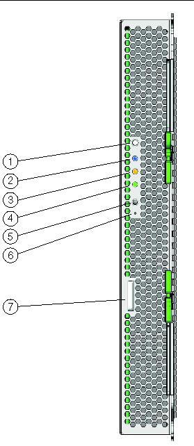
FIGURE 1-1 shows the LEDs and buttons on the front panel. Each LED has one or more activity states. The activity depends upon whether the server module is ELOM-based or ILOM-based. For a description of the LED activities, see TABLE 3-1 in Monitoring System Components Using the External Service Action Required Indicator LED.
FIGURE 1-1 Server Module Front Panel

|
UCP (universal connector port) to connect multi-port dongle cable |
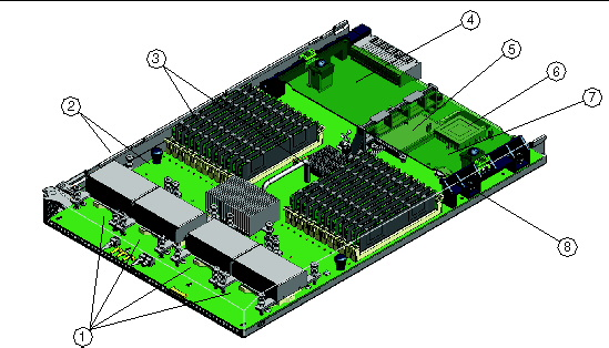
FIGURE 1-2 shows the server module with the top cover removed and the location of the replaceable components.
FIGURE 1-2 Server Module Replaceable Component Locations

|
Battery for optional RAID expansion module, or solid-state drive (SSD) |
|
The Sun Blade X6450 server module has two motherboard (MB) revisions (revision 1 and revision 2). Some optional hardware components, such as a SSD and low voltage DIMMs, work with revision 2 MB only, and some procedures in this manual are specific to revision 2 motherboards. Before performing a revision 2 specific procedure, or installing optional components, you need to determine the revision of your server module. This section describes how to identify your server module’s MB revision.
You have the following options for determining the revision level of your server module:
|
1. Power off the server module, and remove the server module from the chassis (see To Remove the Server Module From the Chassis).

|
Caution - Possible chassis shutdown. Do not operate the system with empty slots. Always insert a filler into an empty slot to reduce the possibility of module shutdown. |
2. Remove the main cover as described in To Remove the Main Cover.
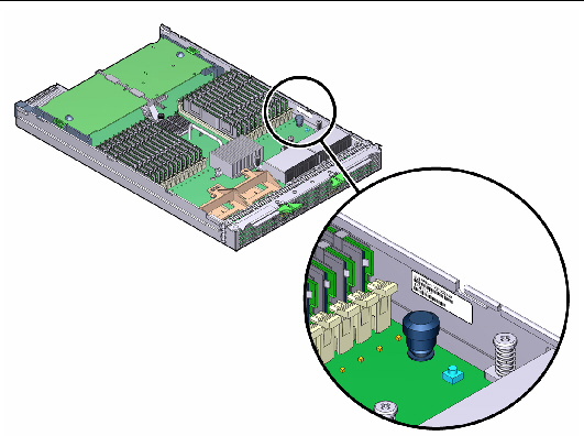
3. Read the FRU part number on the FRU label affixed to the motherboard. See FIGURE 1-2 for the location of the FRU label.
The revision 2 FRU part number is F540-7821-xx.
where xx is irrelevant version information.
FIGURE 1-3 The Location of the FRU ID Label

|
 Log in to either the ELOM or ILOM web interface or CLI. See the corresponding ILOM documentation for more information.
The revision 2 FRU part number is F540-7821-xx.
where xx is irrelevant version information.
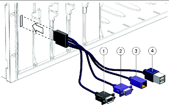
Your chassis ships with a multi-port dongle cable as well as a DB9-to-RJ45 serial adapter cable. The multi-port cable enables you to plug devices directly into the front of the server for maintenance and OS installation purposes. The multi-port cable provides connections for a VGA monitor, two USB devices, and an RJ45 device (see FIGURE 1-4). The DB9-to-RJ45 serial adapter cable provides DB9 serial access to the server module through an RJ45 connection.
|
1. Insert the multi-port dongle cable into the universal connector port (UCP) on the server module front panel. See FIGURE 1-1.
2. Connect the multi-port dongle cable connections as appropriate.
FIGURE 1-4 Dongle Cable Connections

|
VGA video connector. Note: this connector is not present on a three-connector dongle |
|
|
- On a three-connector dongle, this connector provides serial access to the service processor. |
|
TABLE 1-2 lists the contents of the accessory kit that is shipped with the servers.
|
Where to Find Sun Blade X6450 Server Module Documentation (printed sheet) |
|
Supported components and their part numbers are subject to change over time. For the most up-to-date list, go to:
http://sunsolve.sun.com/handbook_pub/Systems/
Click the name and model of your server. On the product page that opens for the server, click on Full Components List for a list of components.
| Note - These servers are fully compliant with the Reduction of Hazardous Substances (RoHS) Directive. |
Customer Replaceable Units (CRUs) are designed to be replaced by customers. Field Replaceable Units (FRUs) must be replaced by Sun service personnel.

|
Caution - Changing FRUs can damage your equipment and void your warranty. |
TABLE 1-3 lists the CRUs and FRUs.
Copyright © 2009 Sun Microsystems, Inc. All rights reserved.