| C H A P T E R 3 |
|
Maintaining the Server |
This chapter contains information and procedures for servicing your Sun Blade X6450 server module hardware, including component removal and replacement procedures.
The following topics are covered in this section:
You can monitor the status of system components using the external front panel Service Action Required LED, the ELOM or ILOM web interface, or the ELOM or ILOM command-line interface (CLI).
This section contains the following procedures:
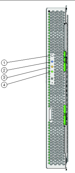
The Service Action Required LED, which is located on the server front panel, enables you to monitor the server’s status. The state of the LED alerts you to the condition of the server module. FIGURE 3-1 shows the locations of the Service Action Required LED. TABLE 3-1 describes the LED states of all the front panel LEDs, including the Service Action Required LED.
When you use the Service Action Required LED in conjunction with the internal fault LEDs, you can isolate server issues to a specific component, such as a CPU or a DIMM.
For more information about using the external front panel LED and the internal fault LEDs to troubleshoot server issues, see Troubleshooting Server Issues.
You can use the ELOM web interface or the ILOM web interface to monitor the status of the server module, and investigate the system when the front panel Service Action Required LED is on or blinking.
|
1. Log in to the web interface, as described in your SP documentation.
2. View system and component information:
a. Click the System Monitoring tab, and use the submenu screens to view system information and component status.
TABLE 3-2 lists the System Monitoring submenu tabs and the monitoring tasks that you can perform.
b. To view component information, click the Components submenu tab.
The Components CPU, Memory, and NIC submenu tabs appears (see FIGURE 3-2).
FIGURE 3-2 The Components Submenu Tabs
The ELOM’s Components submenu screens allows you to monitor and troubleshoot the server module’s critical components, the CPUs, the memory (DIMMs), and the NIC. Use the CPU and Memory screens in conjunction with the Service Action Required LED to further investigate service-related issues.
c. Click the submenu screens to view component information.
TABLE 3-3 lists the System Monitoring tabs and the tasks that you can perform.
|
View events, including details such as event ID, class, type, severity, date and time, and description of event. |
For more information about using the web interface to monitor and manage the server, see Sun Blade X6450 Server Module Embedded Lights Out Manager Administration Guide.
Use the System Information and the System Monitoring tabs to monitor the system and components.
a. Click the System Information tab, and use the submenu screens to view system and component information.
TABLE 3-4 lists the System Information tabs and the task that you can perform.
|
Change the SP(BMC) identification information, such as hostname and address. |
b. See your ILOM documentation collection for more information about using the System Information tab to monitor and manage the server.
c. Click the System Monitoring tab.
The System Monitoring submenu screens appear. TABLE 3-5 lists the submenu tabs and the tasks that you can perform.
d. See the corresponding ILOM documentation collection for more information about using the System Monitoring tab to monitor and manage the server.
You can use the ELOM or ILOM CLI to monitor the status of the server module, and to investigate the system when the front panel Service Action Required LED is on or blinking.
|
1. Log in to the CLI, as described in the Embedded Lights Out Manager Administration Guide.
2. Navigate to either the /SP or the /SYS namespace, and use the command reference in the Embedded Lights Out Manager Administration Guide to execute the necessary commands to view system information and component status.
TABLE 3-6 shows the CLI namespaces and the monitoring tasks that you can perform.
3. To use the CLI to troubleshoot in conjunction with the Service Action Required LED, navigate to either the /SYS/CPU or the /SYS/Memory namespace, and view individual component information:
a. To view the /SYS/CPU namespace:
Executing the show command returns the following:
Navigate to one of the CPU namespaces and view properties for that namespace:
-> cd CPU0
-> show
/SYS/CPU/CPU0 Targets: Properties: Designation = CPU 0 Manufacturer = Intel Name = Tigerton Speed = 2933MHz Status = enabled Target Commands: show |
b. To view the /SYS/Memory namespace:
Executing the show command returns the following:
Navigate to one of the DIMM namespaces:
-> cd DIMM_A0
-> show
For more information about using the CLI to monitor and manage the server, see Embedded Lights Out Manager Administration Guide.
/SYS/Memory/DIMM_A0 Targets: Properties: Designation = DIMM_A0 Type = FBDIMM Size = 2048MB Speed = 667MHz Status = ok Target Commands: show |
|
1. Log in to the CLI, as described in the Sun Integrated Lights Out Manager 2.0 User’s Guide.
2. Navigate to either the /SP/faultmgmt or the /SYS namespace for the server module using one of the following commands:
-> cd /SP/faultmgmt on ILOM 2.0
-> cd /SP/alertmgmt on ILOM 3.0
See the corresponding ILOM documentation collection for additional information.
This section contains preparatory service procedures and other information, including a list of required tools and supplies, and information about obtaining up-to-date supported components and part numbers.
The server can be serviced with the following items:
Supported components and part numbers are subject to change over time. For the most up-to-date list, go to:
http://sunsolve.sun.com/handbook_pub/Systems/
Click the name and model of your server, and click then Full Components List for the list of components and part numbers.
The following basic procedures describe how to prepare the server module for service. The procedures describe how to safely remove the server module from the chassis and how to remove the top cover. These procedures are referenced throughout this manual:
|
To replace components or access the Remind button, you need to remove the server module from the chassis.
1. Place the server in standby power mode. See Chapter 2 for information about powering the server on and off.
When the server is in standby power mode, the Power/OK LED on the front panel begins blinking.
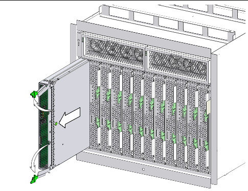
2. Remove the server module from the chassis. See FIGURE 3-3.
a. Squeeze and hold green ejector buttons.
b. Open the ejector levers by rotating the ejector arms away from the server module.
This action unseats the server module from the chassis connector.
c. Pull the server module out of the chassis by the ejector levers until you are able to grasp the module with both hands to pull it out of the chassis.
FIGURE 3-3 Removing a Server Module

|
Caution - Do not operate the system with empty slots. Always insert a filler into an empty slot to reduce the possibility of module shutdown. |
3. Set the server module on an antistatic surface.
|
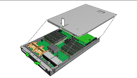
1. Press down on the cover release button and, using the indent for leverage, slide the main cover toward the rear of the chassis approximately 0.5 inch (12 mm). See FIGURE 3-4.
2. Grasp the cover by its rear edge and lift it straight up from the chassis.
FIGURE 3-4 Removing the Main Cover
|
1. Locate the desired slot in the chassis.
Pull the lever out and eject the filler panel.
Do not discard the filler panel.

|
Caution - Do not operate the system with empty slots. Always insert a filler panel into an empty slot to reduce the possibility of module shutdown. |
3. Position the server module vertically so that the ejectors are on the right.
The following illustrations show the server module being inserted into the Sun Blade 6000 modular system; your chassis might differ. See FIGURE 3-5, box 1 in [1].
FIGURE 3-5 Inserting the server module.
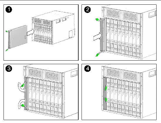
4. Push the server module into the slot until the server module stops.
See FIGURE 3-5 [2].
5. Rotate the ejectors down until they snap into place.
The server module is now flush with the chassis, and the ejectors are locked. See FIGURE 3-5 boxes 3 and 4 in [3,4].
If the chassis is powered on, the server module comes up to standby power. The green OK LED on the front panel blinks.
You can use the external front panel Service Action Required LED to monitor the status of the server (for location, see FIGURE 3-1). When the LED is on or blinking, the server is in need of maintenance.
|
1. Place the server in standby mode.
The Power/OK LED blinks when the server is in standby mode.
2. Choose one of the following methods to troubleshoot the issue:
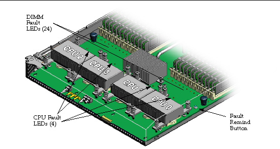
The Sun Blade X6450 server module has internal Fault Indicator LEDs for each DIMM slot and each CPU. When the external front panel Service Action Required LED is on or blinking, you can eject the server module from the chassis, remove the cover, and press the internal Remind button to blink the internal Fault Indicator LED for the failed component(s). This allows you to identify the specific CPU or DIMM that is in a fault state.
| Note - The internal fault indicator system is powered by a capacitor. Therefore, once you remove the server module from the chassis, the server module has a limited operational timeframe. |
|
1. Place the server in standby power mode.
The Power/OK LED blinks when the server is in standby mode.
2. Remove the server from the chassis (see To Remove the Server Module From the Chassis).
Set the server on an anti-static surface.
3. Remove the top cover of the server module (see To Remove the Main Cover).
4. Locate the blue Remind button on the motherboard (see FIGURE 3-6).
If a DIMM or CPU has a fault, its LED will blink. See FIGURE 3-6 for the location of the internal Fault Indicator LEDs. Each LED has two states: blinking or off (see TABLE 3-7).
| Note - The Remind button charging circuitry can maintain operation for 30 - 45 minutes. To recharge the circuit, insert the server module in the chassis for approximately 5 minutes. |
FIGURE 3-6 CPU and DIMM Fault Reminder LEDs
6. If necessary, see the following removal and replacement procedure for the CPU or DIMM:
FIGURE 1-2 in Chapter 1 shows the locations of the replaceable components that are documented in this chapter.
This section contains the following component replacement procedures:
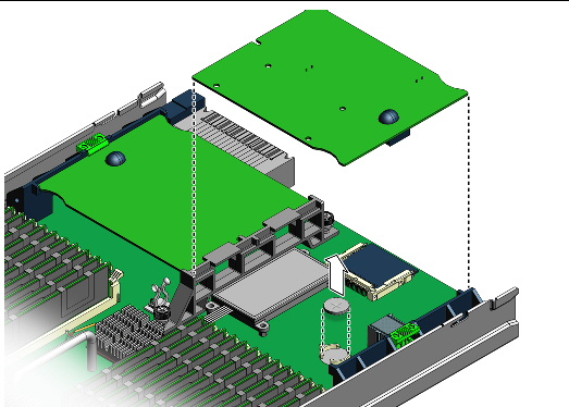
The system battery is a customer replaceable unit (CRU). It is located on the motherboard. If an optional RAID Expansion Module is installed, you must remove the card to access the battery.
1. Power off the server module, and remove the server module from the chassis (see To Remove the Server Module From the Chassis).

|
Caution - Possible chassis shutdown. Do not operate the system with empty slots. Always insert a filler into an empty slot to reduce the possibility of module shutdown. |
2. Remove the main cover as described in To Remove the Main Cover.
3. If a RAID expansion module (REM) card is present, remove the card (see To Remove a RAID Expansion Module).
The system battery is located on the motherboard (see FIGURE 3-7).
4. Remove the battery by gently pulling the clip away from the edge of the battery and lifting the battery straight up. See FIGURE 3-7.
FIGURE 3-7 Removing the Battery
5. To install the battery, reverse Step 1 through Step 4.
| Note - Install the new battery in the holder with the same orientation (polarity) as the battery that you removed. The positive polarity, marked with a “+” symbol, faces upward. |
6. Install the server module cover, and insert the server module into the chassis (see Preparing the Server Module for Service).
The compact flash card is located on the motherboard and accessible from the rear of the server module.
1. If necessary, back up any data that is contained on the compact flash (CF) card.
2. Power off the server and remove the server module from the chassis as described in To Remove the Server Module From the Chassis.

|
Caution - Possible chassis shutdown. Do not operate the system with empty slots. Always insert a filler into an empty slot to reduce the possibility of module shutdown. |
3. Remove the main cover as described in To Remove the Main Cover.
4. Locate the CF card under the RAID Expansion Module at the back of the server module (see FIGURE 3-8).
Your server module might not have a RAID Expansion Module.
| Note - If the optional RAID Expansion Module is installed, you do not need to remove the RAID Expansion Module to remove the CF card. |
FIGURE 3-8 Replacing the Compact Flash
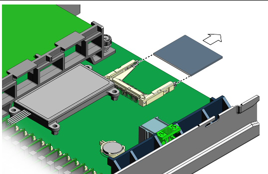
5. Grasp the card, push down slightly, and pull card out.
Installation is the reverse of this procedure.
This section describes how to replace DIMMs. It provides the rules for populating DIMM slots.
The DIMM population rules for the server module are listed here:
TABLE 3-8 shows the population rules based on the number of DIMMs.
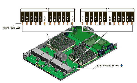
FIGURE 3-9 shows the DIMM numbering and positions
FIGURE 3-9 DIMM Numbering and Position
1. Power off the server and remove the server module from the chassis as described in To Remove the Server Module From the Chassis.

|
Caution - Possible chassis shutdown. Do not operate the system with empty slots. Always insert a filler into an empty slot to reduce the possibility of module shutdown. |
2. Remove the main cover as described in To Remove the Main Cover.
3. Press the Remind button on the motherboard to blink the LED for the DIMMs that have failed (for the location of the Remind button, see FIGURE 3-6).
4. Locate the DIMM slot on the motherboard.
A lit LED next to a DIMM slot indicates a faulty DIMM:
Before continuing to the next step, review the guidelines in DIMM Population Rules.
a. Rotate both DIMM slot ejectors outward as far as they will go.
This action partially ejects the DIMM from the slot.
b. Carefully lift the DIMM straight up to remove it from the slot (see FIGURE 3-10).

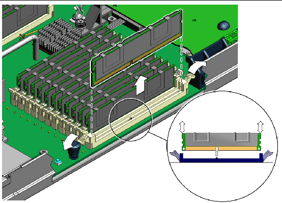
a. Ensure that the DIMM slot ejectors at each end of the memory socket are fully open (rotated outward).
b. Align the notch on the bottom edge of the DIMM with the key in the DIMM slot. See the inset in FIGURE 3-11.
FIGURE 3-11 Installing a DIMM with Slot Alignment Key
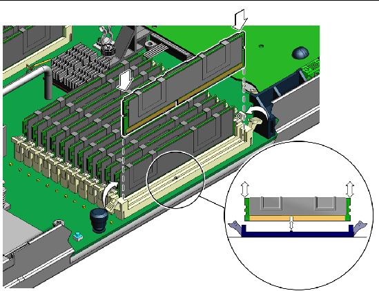
c. Press down evenly on both top corners of the DIMM until the ejectors rotate upward and snap into place. See FIGURE 3-11.
7. Install the server module main cover, and insert the server module into the chassis.
8. Use the SP to verify and view DIMM component information. See the corresponding ELOM or ILOM documentation collection.
Use this procedure to replace a CPU or a CPU and heatsink. To complete this procedure, you need to identify the failed CPU, remove the heatsink and CPU, and install the new components, taking care to apply a uniform layer of thermal compound on top of the CPU.
|
1. Power off the server and remove the server module from the chassis as described in To Remove the Server Module From the Chassis.

|
Caution - Do not operate the system with empty slots. Always insert a filler into an empty slot to reduce the possibility of module shutdown. |
2. Remove the main cover as described in To Remove the Main Cover.
3. Press the Remind button on the motherboard to blink the LED for the CPU that has failed (for the location of the Remind button, see FIGURE 3-6).
4. Identify which CPU and heatsink you are replacing.
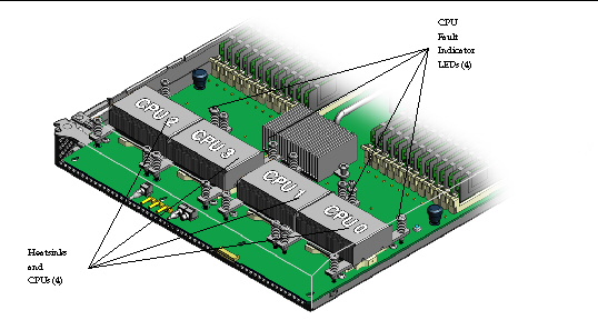
The numeric designation of the four CPUs in the server and the CPU fault LEDs are shown in FIGURE 3-12. There is a fault LED on the motherboard for each CPU:
FIGURE 3-12 The Internal Numbering Designation of the CPUs and the CPU Fault LEDs
5. To remove the heatsink from the motherboard:
a. Gently press down on the top of the heatsink to counteract the pressure of the captive spring-loaded screws that secure the heatsink to the motherboard.
b. Alternately loosen each of the four spring-loaded mounting screws that secure the heatsink to the motherboard. See FIGURE 3-13.
Turn each screw 180 degrees at a time.
FIGURE 3-13 Removing the Heatsink and CPU
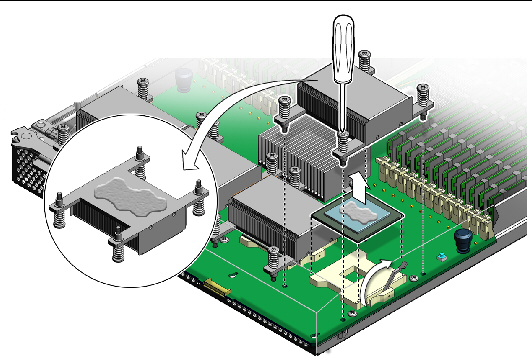
c. To separate the heatsink from the top of the CPU, gently wiggle the heatsink left and right, while pulling upward.
A thin layer of thermal compound separates the heatsink and the CPU. This compound also acts as an adhesive.
d. When the heatsink separates from the CPU, set the heatsink aside.
Do not allow the thermal compound to contaminate the work space or other components.
e. If you are reinstalling the original CPU, use an alcohol pad and clean all of the old thermal compound from the component surface now, before you remove the CPU. You will need to apply new thermal compound when you reinstall the heat sink in Step 8.
a. Lift the lever to the fully open position.
b. Lift the CPU out of the socket, leaving the lever in the open position.
7. To install the new CPU, or install the existing CPU:
a. Ensure that the CPU socket release lever is in the fully open position.
b. Align the CPU over the CPU socket.
Use the triangle symbols on the CPU and the CPU socket for proper alignment.
c. Gently set the CPU on the socket.
When properly aligned, the CPU sits flat in the CPU socket and has minimal side-to-side movement.
d. When the CPU is in the socket, lower the release lever down and into the locked position, at the side of the socket.
This action secures the CPU in the socket.
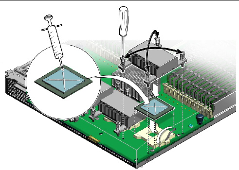
a. Using one syringe of thermal compound (500 mg [0.2 ml]), carefully apply the compound to the top of the CPU in an X pattern as shown in FIGURE 3-14.
b. If you are reinstalling an existing heatsink, use an alcohol pad to clean all the old thermal compound from the bottom surface of the heatsink. Also, clean any dust from the heatsink fins.
c. Carefully position heatsink over the CPU, and align the heatsink screws with the screw holes in the motherboard.
d. Lower the heatsink onto the CPU.
e. Gently press down on the top of the heatsink to counteract the pressure of the captive spring-loaded screws, and use a #2 screwdriver to alternately tighten the each screw, 180 degrees at a time, until tight (see FIGURE 3-14).
| Note - After replacing the CPU, you must update the BIOS and firmware, as described in Chapter 5, Updating ELOM Firmware. |
This section describes how to add and remove a RAID expansion module (REM).
Your server module supports two types of RAID expansion modules:
| Note - RAID expansion modules are installed in the right side bay, over the compact flash card socket and the system battery. |
Use the following procedures to install a RAID Expansion Module (REM).
| Note - The Sun Blade REM includes a battery and four screws. The battery mounts on the motherboard under the RAID Expansion Module. The four screws secure the battery to the motherboard. |
1. Power off the server and remove the server module from the chassis as described in To Remove the Server Module From the Chassis.

|
Caution - Do not operate the system with empty slots. Always insert a filler into an empty slot to reduce the possibility of module shutdown. |
2. Remove the main cover as described in To Remove the Main Cover.
3. Remove the RAID expansion module, battery, and battery mounting screws from the packaging.
The battery mounts on the motherboard under the RAID expansion module. The four screws secure the battery to the motherboard.
4. Orient the battery with the connector and cable facing toward the front of the server (see FIGURE 3-15).
FIGURE 3-15 Installing a RAID Expansion Module Battery
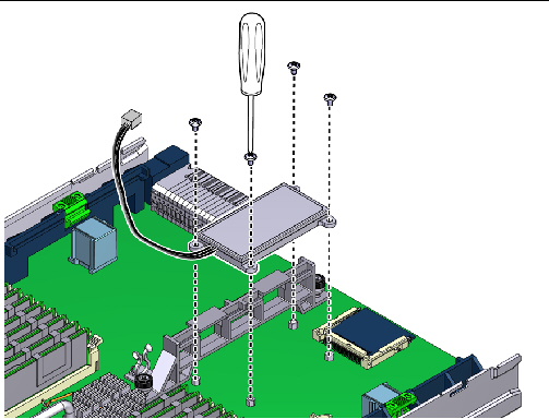
5. Align the battery screw-hole flanges over the four screw hole stand-offs in the motherboard.
6. Use a #2 screwdriver and the four screws to secure the battery to the motherboard.
7. Secure the battery cable to the motherboard using the installed twist-lock.
8. Install the RAID expansion module as described in To Install a RAID Expansion Module. Be sure to complete the steps that describe how to connect and route the battery cable.
If you are installing a Sun Blade RAID 5 expansion module, install the battery, as described in To Install a Sun Blade RAID 5 Expansion Module Battery before proceeding.
1. If you have not already done so, prepare the system for servicing.
a. Power off the server and remove the server module from the chassis as described in To Remove the Server Module From the Chassis.

|
Caution - Do not operate the system with empty slots. Always insert a filler into an empty slot to reduce the possibility of module shutdown. |
b. Remove the main cover as described in To Remove the Main Cover.
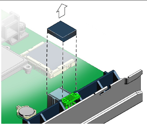
2. Remove the cap from the RAID expansion module connector on the motherboard (see FIGURE 3-16).
The connector cap covers and protects the connector when a REM is not installed.
FIGURE 3-16 Removing the Cap From the REM Connector
3. Position the RAID expansion module with the connector and extension cable facing downward, aligning the connector on the card over the connector on the motherboard.
| Note - The Sun Blade RAID 0/1 expansion module does NOT have a cable. |
4. Connect and route the cable (Sun Blade RAID 5 expansion module only).
If you are installing a Sun Blade RAID 0/1 raid expansion module, skip this step.
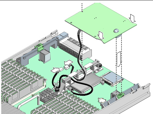
a. (Connect the extension cable to the connector on the end of the battery cable (see FIGURE 3-17).

|
Caution - Damage to the system can occur if the cable is improperly routed. Thermal issues require that you route the cable away from the battery, as described in this procedure. |
b. Route the cable through the opening in the center support bracket. See FIGURE 3-17.
Because of thermal issues, cable routing is critical. Ensure that the cable is routed away from the battery and through the bracket opening nearest the center of the server.
FIGURE 3-17 Routing the Cable and Installing the RAID Expansion Module
5. Install the RAID Expansion Module:
a. Slide the edge of the RAID Expansion Module into the clips on the support bracket.
b. Press the card carefully down into the REM connector until the edge of the card is secured under the eject lever clip (see FIGURE 3-17).
6. Route and secure the cable (Sun Blade RAID 5 expansion module only).
a. Gently pull as much of the cable as possible through the opening in the center support bracket
b. Secure the cable in the cable twist-lock (see FIGURE 3-17).
If you replaced an existing RAID Expansion Module, you are done. If you are adding a RAID Expansion Module to a system that originally did not have one, see the following documents:
For information about configuring RAID on a Linux system, see:
For information about configuring RAID on a Windows system, see:
To remove a RAID expansion module and battery, or to remove only the battery, first remove the RAID expansion module and then remove the battery. The battery is mounted on the motherboard under the RAID expansion module. The removal process is described in following sections:
| Note - The RAID expansion module battery should be replaced when indicated in the Sun StorageTek RAID Manager Software User's Guide, 820-1177. |
1. Power off the server and remove the server module from the chassis as described in To Remove the Server Module From the Chassis.

|
Caution - Do not operate the system with empty slots. Always insert a filler into an empty slot to reduce the possibility of module shutdown. |
2. Remove the main cover as described in To Remove the Main Cover.
3. Disconnect the battery cable from the RAID expansion module extension cable (Sun Blade RAID 5 expansion module only).
The battery is mounted on the motherboard under the RAID expansion module. The cable is routed through the center support bracket and secured by a cable twist-lock. The battery cable connects to one end of the extension cable. The other end of the extension cable is connected to the RAID expansion module.
4. To release the RAID expansion module, press down on the ejector lever (see FIGURE 3-18).
FIGURE 3-18 Removing a RAID Expansion Module
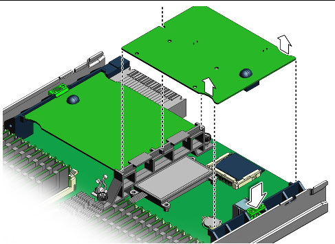
5. To remove the RAID expansion module, grasp the edges of the card, nearest the ejector lever, and carefully lift, tilting the card upward slightly, until the card is free of the connector.
The other edge of the card is secured under the clips on the support bracket.
6. When the card is disconnected, pull the card away from the support bracket.
To install a RAID expansion module, see To Install a RAID Expansion Module.
1. Remove the RAID expansion module as described in the procedure, To Remove a RAID Expansion Module.
2. Use a #2 Phillips screwdriver to remove the four screws that secure the REM battery to the motherboard.
3. Lift and remove the battery.
To install a battery, see To Install a Sun Blade RAID 5 Expansion Module Battery.
The procedures in this section describe how to install and remove a Fabric Expansion Module (FEM). The module is installed on the left side of the center mounting bracket.
1. Power off the server and remove the server module from the chassis as described in To Remove the Server Module From the Chassis.

|
Caution - Do not operate the system with empty slots. Always insert a filler into an empty slot to reduce the possibility of module shutdown. |
2. Remove the main cover as described in To Remove the Main Cover.
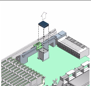
3. Remove the protective cap from the fabric expansion module connector (see FIGURE 3-19).
The fabric expansion module connector is located on the left side of the center support bracket.
FIGURE 3-19 Removing the connector cap
4. Position the fabric expansion module (connector side down) over the fabric expansion module connector on the motherboard, and insert the (opposite) edge of the fabric expansion module into the slots on the center support bracket (see FIGURE 3-20).
FIGURE 3-20 Installation of a Fabric Expansion Module
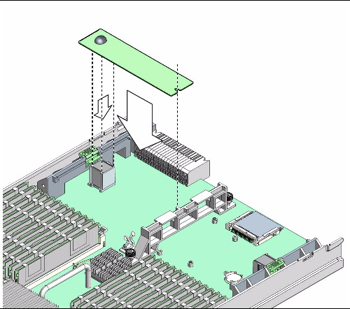
5. Gently press the connector on the underside of the fabric expansion module onto the connector on the motherboard, until the edge of the board is secured by the ejector clip on the left-side support bracket.
The fabric expansion module is installed.
1. Power off the server and remove the server module from the chassis as described in To Remove the Server Module From the Chassis.

|
Caution - Do not operate the system with empty slots. Always insert a filler into an empty slot to reduce the possibility of module shutdown. |
2. Remove the main cover as described in To Remove the Main Cover.
The fabric expansion module connector is located on the left side of the center support bracket.
3. Press down on the ejector lever to unlock the edge of the fabric expansion module.
The ejector lever is located on the left-side support bracket. Unlocking the module allows you to disconnect the module from the motherboard.
4. To disconnect, gently lift the edge of the module off the connector on the motherboard.
The other end of the module is secured under clips on the center support bracket (see FIGURE 3-21).
FIGURE 3-21 Removing a Fabric Expansion Module
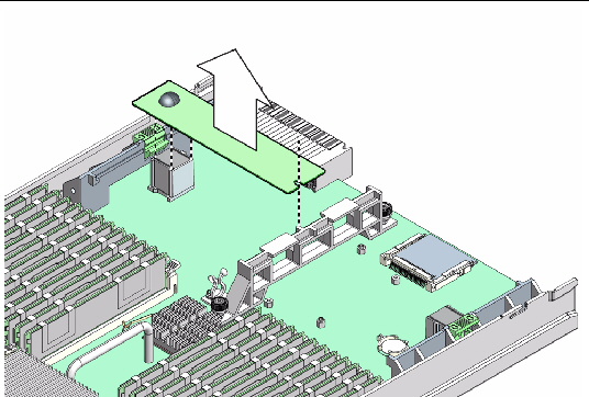
5. When the module is disconnected, pull the card away from the center support bracket, and remove it from the server.
The procedures in this section describe how to install and replace the optional solid-state drive (SSD). The system supports a single SSD, which is installed in the right side bay near the compact flash socket and the system battery.
The SSD is connected to the motherboard (MB) and is controlled by the onboard SATA2. No additional controller hardware is required. The MB must be revision 2. For revision 2 information, see Identifying Sun Blade X6450 Server Module Revisions.
| Note - Because the solid-state drive uses the same mounting hardware as the Sun Blade RAID 5 expansion module battery, you cannot install both the Sun Blade RAID Expansion Module and the SSD. For more information, see Installing or Replacing an Optional Solid-State Drive (SSD) (FRU). |
If your server contains a Sun Blade RAID 5 expansion module, you cannot install the optional SSD, because the Sun Blade RAID 5 expansion module requires a separate battery, which is mounted on the MB using the same mounting hardware that is used for mounting the SSD.
If your system contains the optional Sun Blade RAID 0/1 Expansion module, you can install the SSD because this expansion module does not require a battery and the use of the mounting hardware.
If the Sun Blade 6450 server module is configured to work with a Sun Blade 6000 Disk Module, the disks in the disk module operate as if they were actually on the Sun Blade X6450 server module. This means that:
SSDs must meet the following conditions.
This section describes how to install an SSD. To do this, you must first remove any installed optional expansion modules. For example, if your server contains a Sun Blade RAID Expansion Module and a Sun Blade 10 GigabitEthernet Multi-Fabric Network Express Module, remove these first to access mounting hardware and connectors on the motherboard.
The SSD is installed in a bracket that is mounted to the motherboard, in the right side bay, underneath the optional Sun Blade RAID Expansion Module. Before you install the SSD mounting bracket, you must first route the SATA/power cable assembly through the center support bracket. One end of the cable attaches to connectors on the left side bay, underneath the optional Sun Blade 10 GigabitEthernet Multi-Fabric Network Express Module, which must be removed.
1. Verify that your server module is the correct revision.
The server module must be revision 2 or newer.
2. Verify that your server module contains the appropriate BIOS and SP (for more information, see the Sun Blade X6450 Server Module Product Notes).
3. Power off the server and remove the server module from the chassis as described in To Remove the Server Module From the Chassis.

|
Caution - Do not operate the system with empty slots. Always insert a filler into an empty slot to reduce the possibility of module shutdown. |
4. Remove the main cover as described in To Remove the Main Cover.
5. If necessary, remove and retain the optional RAID expansion module (see To Remove a RAID Expansion Module).
6. If necessary, remove and retain the optional fabric expansion module (see To Remove a Fabric Expansion Module).
7. Remove the cable, the SSD mounting bracket, the SSD, and the two packets of screws from the packaging.
The SSD packaging contains two sets of screws, one set of (shorter) M3 x 4.5L screws, which are used to fasten the SSD mounting bracket to the motherboard and one set of (longer) M2.5 x 5L screws, which are used to fasten the SSD to the SSD mounting bracket.
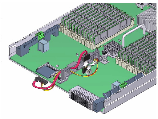
8. Route the cable through the large rear-most opening in the center support bracket so that the end of the cable with two connectors is on the left side of the bracket (see FIGURE 3-22).
The two ends attach to connections on the left side of the motherboard.
9. Press the larger of the two cable ends (SATA data) into the black connector on the motherboard labeled “SATA” (see FIGURE 3-22).
The connection is keyed for proper installation.
10. Press the other end of the cable (SSD power) into the white connector labeled JP5 (see FIGURE 3-22).
FIGURE 3-22 SSD Cable Routing and Connectors
11. Take up any slack in the cable by gently pulling the excess cable through the center support bracket and towards the right side.
Do not place any strain on the motherboard connectors.
12. Position the four holes in the SSD mounting bracket over the four threaded standoffs on the motherboard so that the open end of the mounting bracket is toward the rear of the server (see FIGURE 3-23).
The four standoffs are located on the right side of the center support bracket.
FIGURE 3-23 Installation of the SSD Mounting Bracket
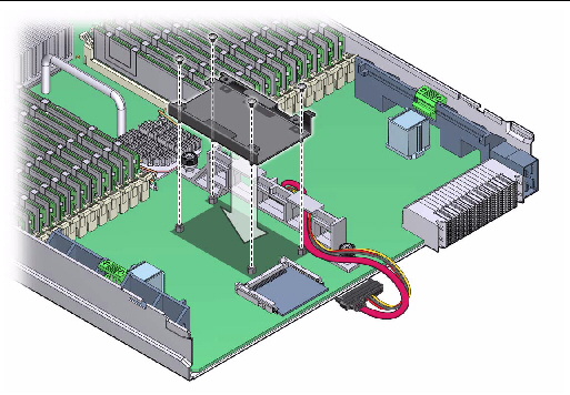
The mounting bracket has a cable retaining flange, which is used to hold the cable in place against the center support bracket.
13. Position the cable behind the retaining flange on the mounting bracket (see FIGURE 3-23).
The flange must hold the cable against the center support bracket.
FIGURE 3-24 Installation of the SSD
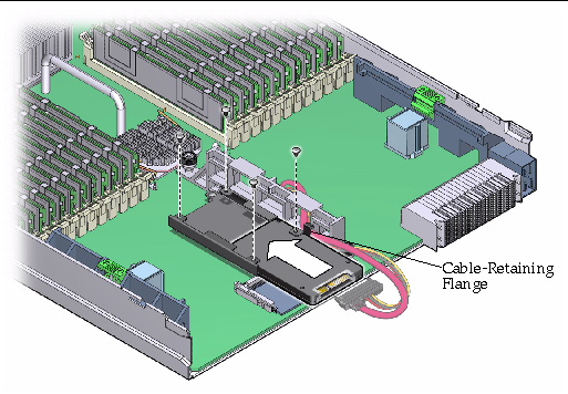
14. Using a #2 screwdriver and the four shorter screws (M2.5 x 4.5L), fasten the mounting bracket to the threaded standoffs on the motherboard.
You must use the shorter (M2.5 x 4.5L) screws. Take care that the cable does not slip away from the retaining flange.
15. Insert the SSD into the mounting bracket so that the screw holes in the SSD face upward (see FIGURE 3-24).
16. Align the four screw holes in the SSD with the four holes in the mounting bracket, and fasten the SSD to the mounting bracket using the four remaining (longer) screws (see FIGURE 3-24).
Use the longer (M2.5 x 5L) screws.
17. Attach the cable to the SSD connector (see FIGURE 3-24).
The connector is keyed, so there is only one way to attach the connector correctly.
18. If necessary, install the optional Sun Blade RAID Expansion Module (see To Install a RAID Expansion Module).
19. If necessary, install the optional fabric expansion module (see To Install a Fabric Expansion Module).
You might need to position the SSD power and SATA cables to limit contact with the underside of the expansion module.
1. Power off the server and remove the server module from the chassis as described in To Remove the Server Module From the Chassis.

|
Caution - Do not operate the system with empty slots. Always insert a filler into an empty slot to reduce the possibility of module shutdown. |
2. Remove the main cover as described in To Remove the Main Cover.
3. If necessary, remove the Sun Blade RAID Expansion Module (To Remove a RAID Expansion Module).
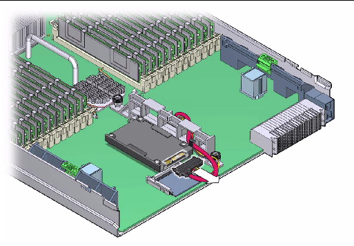
4. Disconnect the cable from the SSD (see FIGURE 3-25).
FIGURE 3-25 Removal of the SSD Cable
5. Use a #2 Phillips screwdriver to remove the four screws securing the SSD to the SSD mounting bracket.
FIGURE 3-26 Removal of the SSD
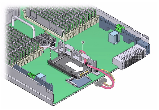
6. To remove the SSD, slide it out of the mounting bracket.
7. Slide the replacement SSD into the mounting bracket so that the screw holes in the SSD face upward.
8. Align the four screw holes in the SSD with four holes in the mounting bracket and secure the SSD to the mounting bracket using the four screws.
9. Attach the cable to the SSD.
The cable is keyed for correct installation.
10. If necessary, install the Sun Blade RAID Expansion Module (see To Install a RAID Expansion Module).
The motherboard is shipped installed in a server module enclosure. Do not remove the motherboard from the enclosure. Instead, remove components from the old motherboard and enclosure assembly, and install these components into the new motherboard and enclosure assembly.
| Note - The motherboard is an FRU and must be replaced only by qualified service technicians. Contact your Sun Service representative for assistance. |
1. Power off the server as described in To Monitor the System and Components Using the SP Web Interface.
2. Remove the server module from the chassis as described in To Remove the Server Module From the Chassis.

|
Caution - Do not operate the system with empty slots. Always insert a filler into an empty slot to reduce the possibility of module shutdown. |
3. Remove the main cover as described in To Remove the Main Cover.
4. Use the following procedures to remove components from the motherboard and install the components on the new motherboard.
5. When the components are installed in the new motherboard, install the cover on the server module, and insert the server module into the chassis (see Preparing the Server Module for Service).
Copyright © 2009 Sun Microsystems, Inc. All rights reserved.